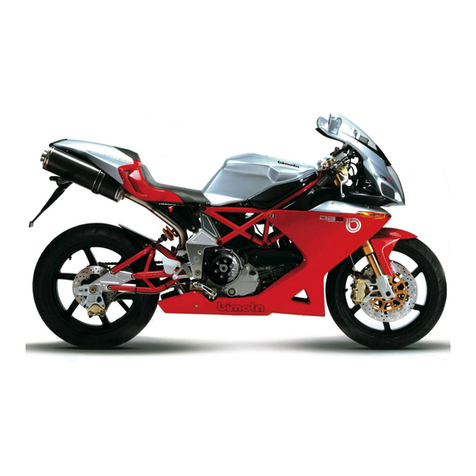
bimota Tesi3D 2009 Instruction manual

MANUALE OFFICINA
WORKSHOP MANUAL
ver. 1.01 12/2009

Tesi3D
II

INDICE
CONTENTS
Tesi3D III
Settore A Part A
1.1 - UTILIZZO DEL MANUALE 1
1.1.1 - Scopo del manuale 2
1.1.2 - Simbologia 3
1.2 - IDENTIFICAZIONE MODELLO 4
1.3 - DATI TECNICI 5
1.3.1 - Generalità 5
1.3.2 - Colori 5
1.3.3 - Ruota anteriore 6
1.3.4 - Sospensione anteriore 6
1.3.5 - Ruota posteriore 6
1.3.6 - Sospensione posteriore 7
1.3.7 - Freni idraulici 7
1.3.8 - Sistema di carica / alternatore 8
1.3.9 - Sistema di accensione 8
1.3.10 - Alimentazione 8
1.3.11 - Sistema di alimentazione 8
1.3.12 - Luci / strumentazione 8
1.4 - COPPIE DI SERRAGGIO 13
1.5 - ATTREZZI SPECIALI 17
2.1 - TABELLA MANUTENZIONE PERIODICA 20
2.2 - CONTROLLO E SOSTITUZIONE OLIO
MOTORE E CARTUCCIA FILTRO 24
2.3 - CONTROLLO E REGISTRAZIONE
TENSIONE CINGHIE DISTRIBUZIONE 26
2.4 - CONTROLLO GIOCO VALVOLE 28
2.5 - REGISTRAZIONE CORPO FARFALLATO 30
2.5.1 - Pareggiamento farfalle 30
2.5.2 - Controllo CO 31
2.6 - MOZZO RUOTA 32
2.6.1 - MONTAGGIO MOZZO SUL CERCHIO 40
2.6.2 - MONTAGGIO DISCHI FRENO SUL
CERCHIO 44
2.7 - EQUILIBRATURA RUOTA ANTERIORE 45
2.8 - REGISTRAZIONE GIOCO CUSCINETTI
DELLO STERZO 46
2.9 - REGISTRAZIONE ASTE AVANCORSA E
ASTE STERZO 47
2.10 - REGISTRAZIONE APERTURA E
ALTEZZA SEMIMANUBRI 48
2.11 - REGOLAZIONE TENSIONE CATENA 49
2.12 - SOSTITUZIONE CANDELE 50
3.1 - VESTIZIONE 51
3.1.1 - Puntalini 51
3.1.2 - Coperchio frizione 51
3.1.3 - Coperchi motore carbonio (serie limitata) 51
3.1.4 - Carene 52
3.1.5 - Cupolino 52
3.1.6 - Selle 53
3.1.7 - Portatarga 54
3.1.8 - Codone 55
3.1.9 - Cavalletto 56
3.1.10 - Comando cambio 56
3.1.11 - Pompa freno posteriore 56
3.1.12 - Pistoncino frizione 56
1.1 - HOW TO USE THE MANUAL 1
1.1.1 - Purpose of the manual 2
1.1.2 - Symbols 3
1.2 - IDENTIFICATION DATA 4
1.3 - TECNICAL SPECIFICATIONS 9
1.3.1 - Description 9
1.3.2 - Colors 9
1.3.3 - Front wheel 10
1.3.4 - Front suspension 10
1.3.5 - Rear Wheel 10
1.3.6 - Rear Suspension 10
1.3.7 - Hydraulic brakes 11
1.3.8 - Charging system / generator 11
1.3.9 - Ignition system 11
1.3.10 - Fuel system 12
1.3.11 - Control unit 12
1.3.12 - Lights / instrument panel 12
1.4 - TORQUE SETTINGS 15
1.5 - SPECIAL TOOLS 17
2.1 - ROUTINE MAINTENANCE TABLE 22
2.2 - CHECKING AND CHANGING ENGINE
OIL AND FILTER CARTRIDGE 24
2.3 - CHECKING AND ADJUSTING TIMING
BELT TENSION 26
2.4 - CHECKING VALVE CLEARANCES 28
2.5 - ADJUSTING THE THROTTLE BODY 30
2.5.1 - Throttles synchronization 30
2.5.2 - Checking the CO level 31
2.6 - FRONT WHEEL HUB 32
2.6.1 - ASSEMBLING HUB ON THE RING 40
2.6.2 - ASSEMBLING BRAKE DISCS ON
THE RING 44
2.7 - BALANCING FRONT WHEEL 45
2.8 - ADJUSTING STEERING BEARINGS
PLAY 46
2.9 - STEERING & FRONTRIDE RODS
ADJUSTMENT 47
2.10 - WIDENESS AND HEIGHT HANDLEBARS
REGISTRATION 48
2.11 - ADJUSTING CHAIN TENSION 49
2.12 - REPLACING THE SPARK PLUGS 50
3.1 - FAIRING 51
3.1.1 - Fairing cap 51
3.1.2 - Clutch cover 51
3.1.3 - Carbon engine cover (limited edition) 51
3.1.4 - Fairings 52
3.1.5 - Front fairing 52
3.1.6 – Seat 53
3.1.7 - Number plate holder 54
3.1.8 - Tail guard 55
3.1.9 - Side stand 56
3.1.10 - Gear change control 56
3.1.11 - Rear brake master cylinder 56
3.1.12 - Clutch slave cylinder 56

Tesi3D
INDICE
CONTENTS
IV
4.1 - SERBATOIO 57
4.2 - IMPIANTO ASPIRAZIONE ARIA 58
4.2.1 - Scatola ltro 58
4.3 - CORPO FARFALLATO 59
4.4 - Serbatoio sato olio 60
4.5 - IMPIANTO DI SCARICO 61
4.6 - CANISTER 63
5.1 - RADIATORE OLIO 64
6.1 - RUOTA ANTERIORE 65
6.1.1 - SOSPENSIONE ANTERIORE 66
6.1.2 - SMONTAGGIO RUOTA ANTERIORE 67
6.1.3 - SCOMPOSIZIONE ELEMENTI RUOTA
ANTERIORE 68
6.2 - FORCELLONE ANTERIORE 69
6.3 - FORCELLONE E SOSPENSIONE
POSTERIORE 70
7.1 - TELAIO / MOTORE 71
7.1.1 - Forcellone posteriore 71
7.1.2 - Forcellone anteriore 71
7.1.3 - Telaio / motore 72
8.1 - IMPIANTO ELETTRICO 74
8.1.1 - Schema elettrico 74
8.1.2 - Cruscotto 75
8.1.3 - Posizionamento cavi (Walbro) 75
9.1 - DIAGNOSI WALBRO TESI 3D 102
9.1.1 - Premessa 102
9.1.2 - Prerequisiti 102
9.2 - Installazione software 102
9.2.1 - Installazione programma di diagnosi
Service OEM 56 102
9.2.2 - Installazione drivers USB 103
9.3 - Connessione al veicolo per la diagnostica 103
9.3.1 - Programma di diagnostica 104
9.3.2 - Visualizzazione parametri in tempo reale 108
9.3.3 - Diagnosi 109
9.3.4 - Fine Linea 110
9.3.5 - Conta Ore 111
9.4 - Installazione programma Windownloader
OEM 2000 112
9.4.1 - Programma di aggiornamento calibrazione 113
4.1 - TANK 57
4.2 - AIR BOX 58
4.2.1 Air box 58
4.3 - THROTTLE BODY 59
4.4 - Oil breather tank 60
4.5 - EXHAUST SYSTEM 61
4.6 - CANISTER 63
5.1 - OIL COOLER 64
6.1 - FRONT WHEEL 65
6.1.1 - FRONT SUSPENSION 66
6.1.2 - DISASSEMBLING FRONT WHEEL 67
6.1.3 - DISASSEMBLING FRONT WHEEL
ELEMENTS 68
6.2 - FRONT WHEEL 69
6.3 - REAR SUSPENSION AND ROCKER
ARM 70
7.1 - FRAME / ENGINE 71
7.1.1 - Rear swing arm 71
7.1.2 - Front swing arm 71
7.1.3 - Frame / engine 72
8.1 - ELECTRIC SYSTEM 74
8.1.1 - Wiring diagram 74
8.1.2 - Digital dashboard 75
8.1.3 - Cables routing (Walbro) 75
9.1 - DIAGNOSIS WALBRO TESI 3D 102
9.1.1 - Introduction 102
9.1.2 - System requirements 102
9.2 - Software installation 102
9.2.1 - Service OEM 56 diagnostic software
installation 102
9.2.2 - USB drivers installation 103
9.3 - Establishing the connection of the serial
cable between pc and the bike 103
9.3.1 - Diagnosis software 104
9.3.2 - Real Time Displaying of The Parameters 108
9.3.3 - Diagnosis 109
9.3.4 - End of line 110
9.3.5 - Hours meter 111
9.4 - Windownloader OEM 2000 software
installation 112
9.4.1 - Upload Calibration software 113

MOTOTELAIO
FRAME
Tesi3D 1
A
1.1 - UTILIZZO DEL
MANUALE
Disposizione degli argomenti
Questo manuale è diviso in due
settori:
A MOTOTELAIO - tratta la
parte ciclistica del veicolo
B MOTORE - tratta la parte
motoristica del veicolo.
Ognuno dei due settori è strut-
turato in modo analogo: viene
diviso in sezioni che trattano
i sottogruppi principali della
parte ciclistica o motoristica del
veicolo.
Le pagine di ciascuna sezione
sono contrassegnate con un
riferimento alla relativa voce
nell’indice generale.
Esposizione delle operazioni
Le operazioni di smontaggio,
montaggio e controllo sono
presentate con l’aiuto di foto-
grae o disegni.
Le fotograe o i disegni conten-
gono dei simboli che indicano
informazioni sui prodotti utiliz-
zati. Vedere la simbologia per
il loro signicato. Le procedure
sono organizzate in modo se-
quenziale, passo-passo.
Riferimenti nel testo
All’interno di un settore
(MOTOTELAIO / MOTORE)
per riferirsi a sezioni, capitoli,
paragra contenute nello stesso
settore si indica solo la nume-
razione corrispondente, mentre
se ci si deve riferire a sezioni,
capitoli, paragra contenu-
ti nell’altro settore oltre alla
numerazione si indica anche la
lettera che identica il settore.
1.1 - HOW TO USE THE
MANUAL
Layout of subjects
This manual consists of two
parts:
A FRAME - dealing with the
vehicle chassis
B ENGINE - dealing with the
vehicle engine.
Each part has a similar layout:
is divided into sections dealing
with the main sub-assemblies
of the vehicle chassis or engi-
ne. Pages of every section bear
a reference to the relevant item
of the general table of contents.
Description of operations
Removal, assembly and in-
spection operations are descri-
bed with the aid of pictures or
drawings. Pictures or drawings
contain symbols giving informa-
tion on products used.
See the symbols key to under-
stand their meaning.
Procedures are described in a
sequence, step by step.
Text cross-references
Inside a part (FRAME/ENGINE)
any cross-reference to sections,
chapters or paragraphs of the
same part is indicated by simply
using the corresponding num-
ber, while any cross-reference
to sections, chapters
or paragraphs of the other part
of the manual is indicated by
the letter identifying the manual
part and the corresponding
number.
Generalità
Description
1

Tesi3D
MOTOTELAIO
FRAME
2
A
1.1.1 - Scopo del
manuale
Questo manuale descrive le
procedure di servizio per gli
interventi di manutenzione,
riparazione e sostituzione di
parti originali del motoveicolo in
oggetto.
I tecnici a cui questo manuale è
destinato devono disporre di
un’adeguata esperienza e
competenza: alcune informazioni
sono state volontariamente
omesse, in quanto devono far
parte dell’indispensabile cultura
tecnica di base che un tecnico
specializzato deve possedere.
I tecnici in fase di utilizzo del
manuale devono rispettare le
caratteristiche tecniche originali
riportate dal Costruttore.
Bimota declina ogni responsa-
bilità per errori ed omissioni di
carattere tecnico, prodotti nella
redazione del presente manuale.
Tutte le informazioni riportate,
sono aggiornate alla data di
stampa.
Bimota persegue una politica
di continua ricerca e sviluppo,
pertanto si riserva il diritto di
apportare modiche ai suoi pro-
dotti senza obbligo di preavviso
e senza l’obbligo di apportare le
stesse modiche a prodotti già
venduti.
La riproduzione, totale o par-
ziale, degli argomenti trattati
nella presente pubblicazione,
è vietata: ogni diritto è riser-
vato a Bimota alla quale si
dovrà richiedere autorizzazio-
ne (scritta) specicandone la
motivazione.
Bimota
1.1.1 - Purpose of the
manual
This manual describes service
procedures for genuine parts
maintenance, repair and replace-
ment interventions of the above-
indicated motor vehicle.
This manual addresses techni-
cians that shall have suitable ex-
perience and knowledge. Some
information has been intentio-
nally omitted, as, our advice, a
specialised technician must have
this technical background.
Technicians are required to
comply with original technical
specications indicated by the
Manufacturer.
Bimota declines all responsibility
for any technical errors or omis-
sions in this manual. The infor-
mation given in this manual
was correct at the time of going
to print.
Bimota focuses on ongoing rese-
arch and development, and thus
reserves the right to make chan-
ges to its products without prior
notice and with no obligation to
make such changes to products
already sold.
Reproduction of all or part of
the contents of this manual is
strictly forbidden. All rights
on this manual are reserved
for Bimota. Applications for
authorisation must be submit-
ted in writing and must specify
the reasons for reproduction
or disclosure.
Bimota
1
Generalità
Description

MOTOTELAIO
FRAME
Tesi3D 3
A
1.1.2 - Simbologia
Tutte le indicazioni destro o
sinistro si riferiscono al senso di
marcia del motociclo.
Attenzione
La non osservanza delle istru-
zioni riportate può creare una
situazione di pericolo e causare
gravi lesioni personali e anche
la morte.
Importante
Indica la possibilità di arrecare
danno al veicolo e/o ai suoi
componenti se le istruzioni
riportate non vengono eseguite.
Note
Fornisce utili informazioni
sull’operazione in corso.
1.1.2 - Symbols
Left-hand and right-hand
in the descriptions refer to
motorcycle direction of travel.
Warning
Failure to follow the instructions
given in text marked with this
symbol can lead to serious
personal injury or death.
Caution
Failure to follow the instructions
in text marked with this symbol
can lead to serious damage to
the motorcycle and its compo-
nents.
Note
This symbol indicates additional
useful information for the cur-
rent operation.
Generalità
Description
1

Tesi3D
MOTOTELAIO
FRAME
4
A
1.2 - IDENTIFICAZIONE
MODELLO
Punzonatura del telaio
Versione Europa
1 Costruttore
2 Modello
3 Variante
4 Versione
5 Anno
6 Sede costruttore
7 N ° progressivo di matricola
Punzonatura del telaio
Versione Stati Uniti
1 Costruttore
2 Modello
3 Check digit
4 Model year
5 Sede costruttore
6 N° progressivo di matricola
1.2 - IDENTIFICATION
DATA
Data punched on frame
European version
1 Manufacturer
2 Model
3 Variant
4 Version
5 Year
6 Plant of manufacture
7 Progressive serial No.
Data punched on frame
USA version
1 Manufacturer
2 Model
3 Check digit
4 Model year
5 Plant of manufacture
6 Progressive serial No.
1
Generalità
Description
ZES*********
Punzonatura del telaio
Versione Stati Uniti
Data punched on frame
USA version
ZES T311D X 8 R 000001
1
2
3
4
5
6
Punzonatura del telaio
Versione Europa
Data punched on frame
Europe version
ZES BT3D 00 7 R 000000
1
2
3
4
5
6
7

MOTOTELAIO
FRAME
Tesi3D 5
A
Generalità
Description
1
Riferimento Dati tecnici
Ingombri del veicolo Lunghezza totale 2100 mm
Larghezza totale 720 mm
Altezza massima 1120 mm
Interasse 1390 mm
Altezza manubrio dall’estremità della
manopola al suolo
765 mm
Altezza sella 810 mm
Altezza pedana pilota 415 mm
Altezza minima da terra 142 mm
Peso a secco 167 kg
Peso a pieno carico 295 kg
Telaio Tipo Telaio in alluminio ad “Omega”
Inclinazione cannotto 20.5°
Angolo di sterzo 22°
Avancorsa 112.7 mm
Cerchio anteriore Forgiato in lega di alluminio
Dimensione cerchio anteriore 3.50 x 17’’
Dimensioni pneumatico anteriore 120 / 70 ZR 17
Cerchio posteriore Forgiato in lega di alluminio
Dimensione cerchio posteriore 5.50 x 17’’
Dimensioni pneumatico posteriore 180 / 55 ZR 17
Tipi di pneumatici CONTINENTAL ContiSport Attack
Freno anteriore Doppio disco semi-ottante ø 320 mm
Freno posteriore Disco ø 220 mm
1.3 - DATI TECNICI
1.3.1 - Generalità
1.3.2 - Colori
Codice Descrizione Descrizione aggiuntiva
900010750 Tesi 3D Rosso-Bianco-Oro EU Edizione Limitata
900010751 Tesi 3D Rosso-Bianco EU Serie 2008
900010772 Tesi 3D Rosso-Bianco-Oro USA Edizione Limitata
900010773 Tesi 3D Carbonio USA Edizione Limitata
900010774 Tesi 3D Carbonio EU Edizione Limitata
900010775 Tesi 3D Carbonio EU Serie 2008
900010783 Tesi 3D Carbonio USA Serie 2008
900010784 Tesi 3D Rosso-Bianco USA Serie 2008

Tesi3D
MOTOTELAIO
FRAME
6
A
1
Generalità
Description
1.3.4 - Sospensione anteriore
Tipo Riferimento Dati tecnici
Ammortizzatore Ad azionamento progressivo
ottenuto con l’interposizione di un
bilanciere tra telaio e fulcro
superiore dell’ammortizzatore.
L’ammortizzatore è regolabile in
estensione, compressione e nel
precarico.
Corsa 50 mm
Posizione standard dei freni idrau-
lici.
Svitare i registri dalla posizione di
tutto chiuso (senso antiorario)
Compressione: da tutto chiuso
ruotare il registro in senso antiorario
di 6 clicks
Estensione: da tutto chiuso ruotare
il registro in senso antiorario di 6
clicks
Precarico della sospensione pressione: 9.5 bar
1.3.5 - Ruota posteriore
Riferimento Valore normale Valore limite
Spessore minimo battistrada Nel punto di massimo consumo 2 mm
Pressione pneumatici A freddo 2.3 bar
Scentratura del perno forcellone Su mm 0.2 mm
Scentratura cerchio ruota Radiale 0.8 mm 2 mm
Assiale 0.5 mm 2 mm
Catena di trasmissione Marca Tipo Regina 135ZRDK-102MG
Dimensioni 5/8’’ x 5/16’’
Numero maglie 102
1.3.3 - Ruota anteriore
Riferimento Valore normale Valore limite
Spessore minimo battistrada Nel punto di massimo
consumo
1.5 mm
Pressione pneumatici A freddo 2.3 bar
Scentratura del perno ruota Su 100 mm 0.2 mm
Scentratura cerchio ruota Radiale 0.8 mm 2 mm
Assiale 0.5 mm 2 mm

MOTOTELAIO
FRAME
Tesi3D 7
A
Generalità
Description
1
Riferimento Valore normale Valore limite
ANTERIORE
Disco del freno Tipo Doppio disco semiottante
forato
Spessore 5 ± 0.1 4.5 mm (min)
Materiale pista frenante Acciaio
Diametro 320 mm
Supercie frenante 39.6 cm2
Pinza freno Marca GRIMECA
Tipo 34-4 Pistoni
Diametro cilindri pinza 34
Materiale attrito pastiglie TOSHIBA TT 2172 HH
Pompa Tipo Pompa idraulica radiale
Diametro cilindro pompa ø 18 mm (R)
POSTERIORE
Disco del freno Tipo Disco sso forato
Spessore 5 ± 0.1 4.5 mm (min)
Materiale pista frenante Acciaio
Diametro 220 mm
Supercie frenante 31.2 cm2
Pinza freno Marca GRIMECA
Tipo 32-2 Pistoni
Diametro cilindro pinza 32 mm
Materiale attrito pastiglie FERODO I/D 450
Pompa Tipo Pompa idraulica
Diametro cilindro pompa ø 11 mm
1.3.7 - Freni idraulici
1.3.6 - Sospensione posteriore
Tipo Riferimento Dati tecnici
Ammortizzatore Fissato direttamente a telaio e for-
cellone con schema “Cantilever”.
Ammortizzatore regolabile in
estensione, compressione e nel
precarico molla.
Corsa 62 mm
Posizione standard dei freni idrau-
lici.
Svitare i registri dalla posizione di
tutto chiuso (senso orario)
Compressione: da tutto chiuso ruo-
tare il registro in senso antiorario di
10 clicks
Estensione: da tutto chiuso ruotare
il registro in senso antiorario di 10
clicks
Precarico molla 10 mm

Tesi3D
MOTOTELAIO
FRAME
8
A
1
Generalità
Description
1.3.10 - Alimentazione
Marca Tipologia
Alimentazione benzina verde 95 - 98 RON
Corpo farfallato ø 45
Iniettori per cilindro 1
Fori per cilindro 4
1.3.11 - Sistema di alimentazione
Marca Tipologia
Centralina WALBRO ECUC-9
1.3.12 - Luci / strumentazione
Riferimento Dati tecnici
Lampadine Faro (Abbagliante / Anabbagliante) H7 (12 V - 55 W)
Luce targa 12 V - 5 W
Luce posizione / arresto 12 V - 5 / 21 W
Luce indicatori direzione posteriore 12 V - 6 W
Luce indicatori direzione anteriore 12 V - 5 W
Fusibili Iniezione 15 A
Indicatore direzione destro 15 A
Indicatore direzione sinistro 15 A
Servizi 7.5 A
Proiettore / clacson 15 A
Quadro strumenti controllo motore 5 A
Regolatore 2 x 25 A
1.3.9 - Sistema di accensione
Riferimento Dati tecnici
Accensione Tipo Elettronica a scarica induttiva
Candele Marca e tipo Champion RA 6 HC-NGK DCPR8E
Distanza degli elettrodi 0.6 ÷ 0.7 mm
Avviamento Tipo Motorino avviamento elettrico
Riferimento Dati tecnici
Batteria Voltaggio 12 V
Capacità 10 Ah
Tipo Ermetico senza manutenzione
Alternatore Capacità 12 V - 520 W
1.3.8 - Sistema di carica / alternatore

MOTOTELAIO
FRAME
Tesi3D 9
A
Generalità
Description
1
Reference Tecnical specications
Vehicle sizes Total length 2100 mm
Total width 720 mm
Maximum height 1120 mm
Wheelbase 1390 mm
Handlebar height - from grip to the ground 765 mm
Seat height 810 mm
Front footpeg height 415 mm
Min. ground clearance 142 mm
Dry weight 167 kg
Weight with full load 295 kg
Frame Type Aluminium “Omega” Frame
Steering head angle 20.5°
Steering angle 22°
Trail 112.7 mm
Front rim Forged aluminum alloy
Front rim size 3.50 x 17’’
Front tyre size 120 / 70 ZR 17
Rear rim Forged aluminum alloy
Rear rim size 5.50 x 17’’
Rear tyre size 180 / 55 ZR 17
Type of tyre CONTINENTAL ContiSport Attack
Front brake Twin disc ø 320 mm
Rear brake Disc brake ø 220 mm
1.3 - TECNICAL SPECIFICATIONS
1.3.1 - Description
1.3.2 - Colors
Codice Description Description
900010750 Tesi 3D Red-White-Gold EU Limited edition
900010751 Tesi 3D Red-White EU Series 2008
900010772 Tesi 3D Red-White-Gold USA Limited edition
900010773 Tesi 3D Carbon USA Limited edition
900010774 Tesi 3D Carbon EU Limited edition
900010775 Tesi 3D Carbon EU Series 2008
900010783 Tesi 3D Carbon USA Series 2008
900010784 Tesi 3D Red-White USA Series 2008

Tesi3D
MOTOTELAIO
FRAME
10
A
1
Generalità
Description
1.3.4 - Front suspension
Type Reference Tecnical specications
Shock absorber Monoshock, with adjustable spring
preload, compression and rebound
Travel 50 mm
Standard damping force setting.
Undo adjusters from the fully closed
position (turn anticlockwise).
Range of adjustment
Compression: From the fully closed
position turn anticlockwise 6 clicks
Rebound: From the fully closed
position turn anticlockwise 6 clicks
Spring preload Pressure: 9.5 bar
1.3.5 - Rear Wheel
Reference Standard value Max allowed value
Trea min. thickness In the most worn position 2 mm
Tyre pressure Cold 2.3 bar
Swingarm shaft eccentricity Over mm 0.2 mm
Wheel rim eccentricity Radial 0.8 mm 2 mm
Axial 0.5 mm 2 mm
Chain Make type Regina 135ZRDK-102MG
Dimensions 5/8’’ x 5/16’’
No. of links 102
1.3.6 - Rear Suspension
Type Reference Technical specications
Shock absorber Monoshock, with adjustable spring
preload, compression and rebound
Travel 62 mm
Standard damping force setting.
Undo adjusters from the fully closed
position (turn anticlockwise).
Range of adjustment
Compression: From the fully closed
position turn anticlockwise 6 clicks
Rebound: From the fully closed
position turn anticlockwise 6 clicks
Spring preload 10 mm
1.3.3 - Front wheel
Reference Standard value Max. allowed value
Trea min. thickness In the most worn position 1.5 mm
Tyre pressure Cold 2.3 bar
Wheel shaft eccentricity On 100 mm 0.2 mm
Wheel rim eccentricity Radial 0.8 mm 2 mm
Axial 0.5 mm 2 mm

MOTOTELAIO
FRAME
Tesi3D 11
A
Generalità
Description
1
Reference Standard value Max. allowed value
FRONT
Brake disc Type Twin drilled semi-oating disc
Thickness 5 ± 0.1 4.5 mm (min)
Material Steel
Diameter 320 mm
Braking surface 39.6 cm2
Brake calliper Make GRIMECA
Type 34-4 Pistons
Calliper cylinder diameter 34
Pads friction material TOSHIBA TT 2172 HH
Brake master cylinder Type hydraulic radial pump
Master cylinder diameter ø 18 mm (R)
REAR
Brake disc Type Drille xed disc
Thickness 5 ±0.1 4.5 mm (min)
Material Steel
Diameter 220 mm
Braking surface 31.2 cm2
Brake calliper Make GRIMECA
Type 32-2 Pistons
Calliper cylinder diameter 32 mm
Pads friction material FERODO I/D 450
Brake master cylinder Type hydraulic pump
Master cylinder diameter ø 11 mm
1.3.7 - Hydraulic brakes
1.3.8 - Charging system / generator
Reference Techinical specications
Battery Voltage 12 V
Capacity 10 Ah
Type Sealed, maintenance free
Generator Capacity 12 V - 520 W
1.3.9 - Ignition system
Reference Tecnical specications
Ignition Type Electronic type with inductive
discharge system
Spark plugs Make and type Champion RA 6 HC - NGK D
PR8E
Electrode gap 0.6 ÷ 0.7 mm
Starting Type Electric starter motor

Tesi3D
MOTOTELAIO
FRAME
12
A
1
Generalità
Description
1.3.10 - Fuel system
Make Type
Unleaded fuel 95 - 98 RON
Throttle body ø 45
Injectors per cylinder 1
Firing points per injector 1
1.3.11 - Control unit
Make type
Control unit WALBRO ECUC-9
1.3.12 - Lights / instrument panel
Reference Technical specications
Bulbs Front headlamp (high beam / low beam ) H7 (12 V - 55 W)
Number plate light 12 V - 5 W
Parking / stop light 12 V - 5 / 21 W
Rear turn indicators light 12 V - 6 W
Front turn indicators light 12 V - 5 W
Fuses Injection 15 A
Right turn indicator 15 A
Left turn indicator 15 A
Services 7.5 A
Headlamp / horn 15 A
Engine control instrument panel 5 A
Regulator 2 x 25 A

MOTOTELAIO
FRAME
Tesi3D 13
A
Generalità
Description
1
1.4 - COPPIE DI SERRAGGIO
Descrizione Misura (mm) Coppia
(Nm) Note
GENERALE
Vite M5 5 5 - 6
Vite M6 6 10 - 12
Vite M8 8 22 - 25
Vite M10 10 50
Vite M12 12 85 - 90
MOTORE / TELAIO
Dado pignone motore M25x1,5 180 Grasso
Dadi perni motore M12x1.25 55 Grasso sotto dado
Viti ssaggio traliccio supporto sospensione posteriore M10x1,25x25 40 Loctite 243
Viti ssaggio traliccio anteriore M8x20 - M8x70 22 Loctite 243
Viti ssaggio telaietto anteriore M6x12 10 Loctite 243
Viti ssaggio codone su traliccio supporto sospensione M24x1 40 Grasso sotto testa
Viti pedana pilota su telaio M8x1,25x18 22 Loctite 243
Viti blocchetto chiave M6x30 10 Loctite 243
Viti regolatore di tensione su traliccio anteriore M6x25 10
Viti centralina su traliccio anteriore M4x20 3 o manuale
FORCELLONE ANTERIORE
Viti ssaggio calotte perno ruota M8x22 22 Loctite 243
Viti perno forcellone M16x1,5x20 AL 55 Grasso sotto testa
Vite ssaggio puntone sospensione al forcellone M12x1,25 80 Grasso sotto testa
FORCELLONE POSTERIORE
Vite + dado ssaggio sospensione M12x1,25 60
Viti ssaggio piastre alluminio M10x1,25 45 Loctite 2701
Viti perno forcellone M16x1,25x20 AL 60 Grasso sotto testa
SISTEMA FRENANTE ANTERIORE
Viti pinze freno M10x1,25x55 45 Grasso sotto testa
Viti supporto pinze freno su mozzo M8 22 Loctite 243
Viti dischi freno su cerchio M6x20 10 Loctite 243
Viti raccordi tubi freno su pinze e pompa M10x1 20
SISTEMA FRENANTE POSTERIORE
Viti pinza freno su slitta tendicatena M8x20 22 Loctite 243
Viti pompa freno su telaio M6x22 - M6x14 10
Viti disco freno su cerchio M8x20 22 Loctite 243
Viti raccordi tubo freno su pinza e pompa M10x1 20
NOTE
La coppia di serraggio si intende applicata lentamente e gradualmente con chiave dinamometrica tarata.
In caso di serraggio con avvitatori automatici a battere, la coppia di riferimento deve essere ridotta del 10%.

Tesi3D
MOTOTELAIO
FRAME
14
A
1
Descrizione Misura (mm) Coppia
(Nm) Note
RUOTA ANTERIORE
Vite ssaggio leva di reazione M18x1,5 AL 45 Grasso sotto testa
RUOTA POSTERIORE
Perno ruota M26x2 100 Grasso sotto testa
Perni + dadi ssaggio corona su angia M10x1,25 50 Loctite 243
SISTEMA DI STERZO
Viti ssaggio aste avancorsa, inferiore e sup. di sterzo M8 22 Loctite 243
SOSPENSIONE ANTERIORE
Vite ssaggio puntone al bilanciere M12x1,25 60 Loctite 243
Vite ssaggio sospensione al bilanciere M12x1,25 60 Loctite 243
Vite + Perno bilanciere M24x1 100 Grasso sotto testa
Loctite 243
M6x65 10 Loctite 243
Vite ssaggio sospensione a supporto posteriore M12x1,25 60 Loctite 243
Viti ssaggio supporto sospensione a motore M10x1,25 45 Loctite 243
M12x1,25 60 Loctite 243
SOSPENSIONE POSTERIORE
Vite ssaggio sospensione al traliccio posteriore M12x1,25 80
Vite + dado ssaggio sospensione al forcellone M12x1,25 60
CANNOTTO
Viti ssaggio testa di sterzo M6x30 11
Tappo ssaggio piastra di sterzo M28x1 AL 30 Grasso sotto testa
Ghiera cannotto M40x1 AL 30 Grasso
SEMIMANUBRI
Viti ssaggio semimanubri M8 22
Grano di sicurezza per semimanubrio M8x6 22 Loctite 243
COMANDI / MANUBRIO
Pompa freno anteriore su semimanubrio DX M6x25 10 - 11
Pompa frizione su semimanubrio SX M6x25 10 - 11
CAVALLETTO LATERALE
Viti ssaggio piastra cavalletto al motore M10x1,5x25 36 Loctite 243
Vite ssaggio stampella M8 20 Loctite 243
NOTE
La coppia di serraggio si intende applicata lentamente e gradualmente con chiave dinamometrica tarata.
In caso di serraggio con avvitatori automatici a battere, la coppia di riferimento deve essere ridotta del 10%.
Generalità
Description

MOTOTELAIO
FRAME
Tesi3D 15
A
1.4 - TORQUE SETTINGS
1
Description Measure (mm) Torque
(Nm) Notes
GENERAL
Screw M5 5 5 - 6
Screw M6 6 10 - 12
Screw M8 8 22 - 25
Screw M10 10 50
Screw M12 12 85 - 90
ENGINE / FRAME
Sprocket nut M25x1,5 180 Grease
Nut tie rod M12x1.25 55 Grease under head
Screw rear support suspension frame M10x1,25x25 40 Loctite 243
Screw front frame M8x20 - M8x70 22 Loctite 243
Screw front frame / headlight M6x12 10 Loctite 243
Screw tail on rear support suspension frame M24x1 40 Grease under head
Screw foot rest on frame M8x1,25x18 22 Loctite 243
Screw steering block M6x30 10 Loctite 243
Screw voltage rectier on front frame M6x25 10
Screw computer unit on front frame M4x20 3 - manual
FRONT SWINGARM
Screw cap wheel pin M8x22 22 Loctite 243
Screw swingarm pivot M16x1,5x20 AL 55 Grease under head
Screw pushrod suspension to swingarm M12x1,25 80 Grease under head
REAR SWINGARM
Screw + Nut suspension M12x1,25 60
Screw aluminium plate M10x1,25 45 Loctite 2701
Screw swingarm pivot M16x1,25x20 AL 60 Grease under head
FRONT BRAKE SYSTEM
Screw caliper M10x1,25x55 45 Grease under head
Screw caliper support on front hub M8 22 Loctite 243
Screw brake disk M6x20 10 Loctite 243
Drilled screw brake line on caliper and pump M10x1 20
REAR BRAKE SYSTEM
Screw caliper on plate chain adjuster M8x20 22 Loctite 243
Screw brake pump on frame M6x22 - M6x14 10
Screw brake disk on wheel M8x20 22 Loctite 243
Drilled screw brake line on caliper and pump M10x1 20
NOTE
The torque is applied slowly and gradually with calibrated torque wrench.
If locking with automatic screwer , the torque of reference must be reduced by 10%.
Generalità
Description

Tesi3D
MOTOTELAIO
FRAME
16
A
1
Generalità
Description
Descrizione Misura (mm) Coppia
(Nm) Notes
FRONT WHEEL
Screw rod reaction lever on wheel pin M18x1,5 AL 45 Grease under head
REAR WHEEL
Wheel axle M26x2 100 Grease under head
Perni + dadi ssaggio corona su angia M10x1,25 50 Loctite 243
STEERING SYSTEM
Screw trail rod, upper and lower steering rod M8 22 Loctite 243
FRONT SUSPENSION
Screw pushrod to rocker arm M12x1,25 60 Loctite 243
Screw suspension to rocker arm M12x1,25 60 Loctite 243
Screw + Rocker arm pin M24x1 100 Grease under head
Loctite 243
M6x65 10 Loctite 243
Screw suspension to support suspension M12x1,25 60 Loctite 243
Screw support suspension to engine M10x1,25 45 Loctite 243
M12x1,25 60 Loctite 243
REAR SUSPENSION
Screw suspension to rear frame M12x1,25 80
Screw + nut suspension to swingarm M12x1,25 60
STEERING TUBE
Screw steering head M6x30 11
Steering head screw M28x1 AL 30 Grease under head
Ring nut M40x1 AL 30 Grease
HANDLEBAR
Screw handlebar M8 22
Dowel handlebar M8x6 22 Loctite 243
CONTROLS / HANDLEBAR
Screw front brake pump on DX handlebar M6x25 10 - 11
Screw clutch pump on SX handlebar M6x25 10 - 11
SIDE STAND
Screw plate side stand to engine M10x1,5x25 36 Loctite 243
Screw side stand M8 20 Loctite 243
NOTE
The torque is applied slowly and gradually with calibrated torque wrench.
If locking with automatic screwer , the torque of reference must be reduced by 10%.
Table of contents
Other bimota Motorcycle manuals
