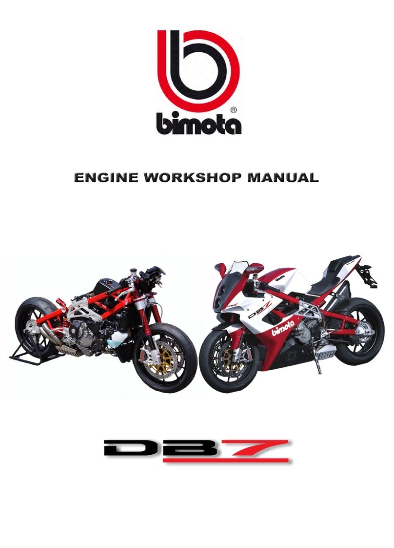
bimota DB7 Instruction manual

Rev. 1.10 11-2009


___________________________________________
BIMOTA DB7
WORKSHOP MANUAL
2008 BIMOTA SPA
All rights reserved
The reproduction, in whole or part, of the topics covered
in this publication, is forbidden: all rights are reserved to
Bimota to which will require (written) authorization
specifying the reasons.
Bimota
I

MANUAL PURPOSE – WARNINGS
This manual has been written by Bimota SpA primarily intended for use by dealers Bimota and their
skilled mechanics.
Describes the service procedures for maintenance, repair and replacement of original parts of the
motorcycle in question.
The technicians, that this manual is intended to, must have the adequate experience and
competence: some information has been deliberately omitted, because they have to be part of the
indispensable basics that a technician must have.
The technicians in the use phase of the manual must comply with the original technical
specifications given by the original manufacturer.
Bimota assumes no responsibility for errors or omissions of technical nature, produced in the
writing of this manual.
All the information provided shall be updated at the time of printing, Bimota pursues a policy of
continuous research and development, therefore, reserves the right to make changes of its
products without prior notice and without obligation to make the same changes to products already
sold.
The modifications or significant changes made to the specifications or procedures will be reported
to all Bimota authorized dealers and, where possible, will be included in subsequent editions of this
manual.
SYMBOLS
All indications right or left refer to the direction of travel of motorcycle.
CAUTION
The non-compliance with the instructions may create a situation of danger and cause serious
personal injury and even the death of the pilot, persons in the proximity, or person intent to repair
the bike.
IMPORTANT
Indicates the possibility of damage to the vehicle and/or its components if the instructions are not
performed.
NOTES
provides useful information on the current operation.
II

USE OF THE MANUAL
This manual is an easy guide for technicians. All the procedures indicated in the manual are
illustrated in a detailed way and regards the operations of disassembly, assembly, inspection and
repair.
1) The manual is divided in chapters. The name and the relative number, placed in a frame
on the right upper corner of each page, indicating the current chapter.
2) Each chapter is divided in sections. In the left upper part of each page is reported the title of
the current section, written in capital letters.
3) Paragraph title, written in small letters respect to the section title.
4) At the beginning of some sections, to make the procedures of disassembly more clear and
to help the identification of the bike components, are reported the exploded drawings. It is
possible to identify by number the related piece.
5) The exploded drawing is accompanied by a list with the piece name and relative
characteristics.
6) The instructions for the disassembly/assembly operations are described in sequence.
7) Some operations are accompanied by symbols with the purpose to supply more information
and/or possible danger situation for the pilot or motorcycle.
________________________ ENGINE 11
11.8 - HEAD UNIT: TIMING SYSTEM
1) External cover vertical belt
2) Air filter
3) External cover horizontal belt
4) Screw
5) Filter cover
6) Screw
7) Washer
8) Lock nut
9) Complete mobile turnbuckle
10) Oil seal
11) Distribution pulley
12) Tightener pivot
13) Complete fixed turnbuckle
14) Distribution toothed belts
15) Ring nut
16) Tongue
17) Spacer
18) Distribution pulley
19) Pulley washer split
20) Spacer
21) Ring nut
22) Screw
23) Washer
24) Flange spacer
________________________ ENGINE 11
Dismantling of timing system countershaft pulleys
Lock with the tool cod. 88713.1805 the rotation of the motive pulleys on the motor carter.
ATTENTION
In the event that the operation is carried out with the engine in frame, lock the rotation of
the motive pulleys using the tool cod. 88713.2011 mounted on the alternator cover.
Loosen the locknut (15) using the bush that came with tool.
Remove the locknut (15), the spacer (20), and the external pulley (18).
Remove the first tongue (16) on the trip shaft of timing system.
Remove the washer split (19) and the internal pulley (18).
III
5
6
1
3
7
2
4

INDEX
GENERAL INFORMATIONS 1
TECHNICAL SPECIFICATIONS 2
USE AND MAINTENANCE 3
BODYWORK 4
CONTROLS AND DEVICES 5
WHEELS-BRAKES-SUSPENSIONS 6
FRAME 7
EXHAUST - INTAKE 8
IV

INJECTION - IGNITION 9
ELECTRICAL SYSTEM 10
V

Table of contents
MANUAL PURPOSE – WARNINGS II
SYMBOLS II
USE OF THE MANUAL III
INDEX IV
CHAPTER 1
GENERAL INFORMATIONS
1.1 - IDENTIFICATION OF THE MOTORCYCLE Sub 1-2
Punching of the frame (European version) ..................................................................Sub 1-2
Punching of the frame (United States version)..............................................................Sub 1-2
Punching of the engine (European / united states version)..........................................Sub 1-3
Frame tag.....................................................................................................................Sub 1-3
1.2 - PRODUCTS SPECIFICATIONS Sub 1-4
1.3 - HAZARDOUS PRODUCTS / WARNINGS Sub 1-5
CHAPTER 2
TECHNICAL SPECIFICATIONS
2.1 -TECHNICAL DATA Sub 2-2
Colors............................................................................................................................Sub 2-2
Particulars.....................................................................................................................Sub 2-2
Engine.......................................................................................................................... Sub 2-2
Drive………...................................................................................................................Sub 2-3
Drive system ................................................................................................................Sub 2-3
Timing system / valves..................................................................................................Sub 2-3
Tension belts adjustment at cold…...............................................................................Sub 2-4
Engine shaft..................................................................................................................Sub 2-4
Cylinder / piston............................................................................................................Sub 2-5
Gearbox........................................................................................................................Sub 2-5
Cooling system.............................................................................................................Sub 2-6
Front wheel...................................................................................................................Sub 2-6
Front suspension..........................................................................................................Sub 2-6
Rear wheel................................................................................................................... Sub 2-7
Final drive.....................................................................................................................Sub 2-7
Rear suspension...........................................................................................................Sub 2-7
Hydraulic brakes...........................................................................................................Sub 2-8
Charging system / alternator.........................................................................................Sub 2-8
Injection system / ignition............................................................................................. Sub 2-9
Intake............................................................................................................................Sub 2-9
Feeding system............................................................................................................Sub 2-9
Lights / dash.................................................................................................................Sub 2-9
VI

2.2 - SIZE Sub 2-10
2.3 - LUBRICANTS AND REFUELING Sub 2-11
2.4 - TORQUE WRENCH SETTINGS Sub 2-12
Frame torque wrench settings......................................................................................Sub 2-12
Engine torque wrench settings.....................................................................................Sub 2-18
2.5 - SERVICE TOOLS Sub 2-21
Specific equipment for engine......................................................................................Sub 2-21
Specific equipment for frame........................................................................................Sub 2-25
CHAPTER 3
USE AND MAINTENANCE
3.1 - PRELIMINARY CHECKS Sub 3-3
Running-in period........................................................................................................ Sub 3-3
Check-up before run.....................................................................................................Sub 3-4
3.2 - STARTING - ENGINE WARM UP Sub 3-5
3.3 - TABLE OF PERIODIC MAINTENANCE Sub 3-6
Dealer operations.........................................................................................................Sub 3-6
Customer operations....................................................................................................Sub 3-7
3.4 - MAINTENANCE OPERATIONS Sub 3-8
Motor oil level control....................................................................................................Sub 3-8
Motor oil and filter cartridge replacement.....................................................................Sub 3-9
Valves clearance check-up.........................................................................................Sub 3-12
Valves clearance adjustment......................................................................................Sub 3-13
Liquid cooling level control.........................................................................................Sub 3-14
Liquid cooling replacement........................................................................................Sub 3-15
Air filters replacement and cleaning...........................................................................Sub 3-16
Front brake fluid replacement.....................................................................................Sub 3-19
Rear brake fluid replacement.....................................................................................Sub 3-20
Brake circuit bleeding ................................................................................................Sub 3-22
Brake circuit filling......................................................................................................Sub 3-24
Clutch liquid replacement...........................................................................................Sub 3-27
Clutch liquid draining..................................................................................................Sub 3-28
Clutch liquid filling.......................................................................................................Sub 3-30
Steering stem bearings clearance adjustment............................................................Sub 3-32
Chain tension adjustment...........................................................................................Sub 3-34
Brake pads wear check-up and replacement.............................................................Sub 3-36
Front brake pads check-up.........................................................................................Sub 3-36
Filling up brake fluid....................................................................................................Sub 3-37
Rear brake pads check-up..........................................................................................Sub 3-37
Throttle cable regulation..............................................................................................Sub 3-39
Clutch lever and front brake lever adjustment............................................................Sub 3-40
Rear brake pedal and shift lever position adjustment.................................................Sub 3-41
Fork adjustment..........................................................................................................Sub 3-42
Rear shock adjustment...............................................................................................Sub 3-44
Steering damper..........................................................................................................Sub 3-46
Rear height regulation / bike trim................................................................................Sub 3-47
VII

3.5 - DIAGNOSTIC INSTRUMENTS Sub 3-48
3.5.1 - Walbro diagnosis.............................................................................................. Sub 3-48
3.6 - Software installation.............................................................................................Sub 3-49
3.6.1 - Installation of diagnosis software Service OEM 564.........................................Sub 3-49
3.6.2 - USB drivers installation.....................................................................................Sub 3-49
3.7 - Vehicle connection for diagnostic.........................................................................Sub 3-49
3.7.1 - Diagnostic software...........................................................................................Sub 3-52
3.7.2 - Real time parameter view..................................................................................Sub 3-55
3.7.3 - Diagnosis...........................................................................................................Sub 3-56
3.7.4 - End of line..........................................................................................................Sub 3-57
3.7.5 - Hour meter.........................................................................................................Sub 3-58
3.8 - Installation of Windownloader OEM 2000 program (use for ECUC).....................Sub 3-58
3.8.1 - Calibration update program...............................................................................Sub 3-59
3.9 - Installation of EcugLoader-1000 program (use for ECUG)...................................Sub 3-61
3.9.1 - Calibration update program...............................................................................Sub 3-61
CHAPTER 4
BODYWORK
4.1 - WINDSHIELD AND REARVIEW MIRRORS Sub 4-2
Rearview mirrors dismantling……………….………………………………………………Sub 4-2
4.2 - FAIRING Sub 4-4
Disassembly of side fairing and lower fairing……..………………………………….….Sub 4-4
4.3 - FRONT FENDER Sub 4-6
Front fender dismantling…………………………………………………………………….Sub 4-6
4.4 - TAIL - SEAT Sub 4-7
Tail dismantling……………………………………………………………………………….Sub 4-7
Seat dismantling….……….………………………………………………………………….Sub 4-8
4.5 - LICENSE PLATE HOLDER – REAR FENDER Sub 4-9
Dismantling of license plate holder……………....…………………………………….….Sub 4-9
Rear fender dismantling…………………………………..……………………………….Sub 4-10
4.6 - REAR FENDER – CHAIN GUARD Sub 4-11
CHAPTER 5
CONTROLS AND DEVICES
5.1 - THROTTLE CONTROL Sub 5-2
Twist throttle dismantling…….......………….………………………………………………Sub 5-3
5.2 - FRONT BRAKE CONTROL Sub 5-4
Disassembly of front brake master cylinder……………..…..……..………………….….Sub 5-5
5.2 - REAR BRAKE CONTROL Sub 5-6
Rear brake dismantling…………..………………………………………………………….Sub 5-7
5.4 - HYDRAULIC CLUTCH CONTROL Sub 5-9
Disassembly of hydraulic clutch pump…………….……..…..……..………………….….Sub 5-5
5-5 – SHIFT CONTROL Sub 5-11
Complete shift lever dismantling..........………....…………………………………….….Sub 5-12
VIII

CHAPTER 6
WHEELS – BRAKES – SUSPENSIONS
6.1 - FRONT WHEEL Sub 6-2
Front wheel dismantling.............................................................................................. Sub 6-3
6.2 – FRONT FORKS Sub 6-5
Forks disassembly.......................................................................................................Sub 6-6
6.3 – FRONT BRAKE Sub 6-8
Front brake disassembly..............................................................................................Sub 6-9
Dual discs dismantling..............................................................................................Sub 6-11
6.4 – REAR WHEEL AND SECONDARY DRIVE Sub 6-12
Rear wheel dismantling.............................................................................................Sub 6-13
Secondary drive check-up.........................................................................................Sub 6-14
Chain washing...........................................................................................................Sub 6-14
Chain lubrication........................................................................................................Sub 6-14
Front sprocket dismantling........................................................................................Sub 6-15
Rear sprocket dismantling.........................................................................................Sub 6-16
Rear wheel check-up.................................................................................................Sub 6-16
6.5 - SWING ARM Sub 6-18
Swing arm disassembly.............................................................................................Sub 6-19
6.6 - REAR BRAKE Sub 6-22
Disassembly of rear brake caliper..............................................................................Sub 6-23
Speed sensor dismantling..........................................................................................Sub 6-24
Rear disc dismantling ...............................................................................................Sub 6-24
6.7 - REAR SHOCK Sub 6-25
Rear shock dismantling.............................................................................................Sub 6-26
Rocker arm dismantling.............................................................................................Sub 6-27
CHAPTER 7
FRAME
7.1 - HANDLEBAR Sub 7-2
Handlebar dismantling................................................................................................ Sub 7-3
7.2 - STEERING Sub 7-5
Steering stem bearings clearance adjustment.............................................................Sub 7-6
Disassembly of steering components..........................................................................Sub 7-6
7.3 - STEERING DAMPER Sub 7-8
Steering damper dismantling.......................................................................................Sub 7-9
7.4 - FOOT PEGS Sub 7-10
Foot pegs support dismantling..................................................................................Sub 7-11
7.5 - KICKSTAND Sub 7-13
Kickstand dismantling............................................................................................... Sub 7-14
Kickstand disassembling.......................................................................................... Sub 7-14
7.1- FRAME AND CHASSIS PLATES Sub 7-16
Frame and structural parts dismantling.................................................................... Sub 7-17
Upper fairing support dismantling............................................................................ Sub 7-17
Frame dismantling................................................................................................... Sub 7-18
IX

7.7 - TAIL Sub 7-19
7.8 - LICENSE PLATE HOLDER Sub 7-20
CHAPTER 8
EXHAUST – INTAKE
8.1 - EXHAUST Sub 8-2
Exhaust dismantling................................................................................................... Sub 8-3
8.2 - FUEL TANK Sub 8-7
Fuel tank dismantling..................................................................................................Sub 8-8
Fuel tank reassembling..............................................................................................Sub 8-8
Fuel pump dismantling...............................................................................................Sub 8-9
Gas cap dismantling...................................................................................................Sub 8-9
8.3 - THROTTLE BODY Sub 8-10
Airbox and throttle body dismantling.........................................................................Sub 8-11
Injectors dismantling.................................................................................................Sub 8-13
Stepper motor dismantling........................................................................................Sub 8-15
Airbox disassembling - throttle body.........................................................................Sub 8-16
8,4 - INTAKE - AIRBOX Sub 8-17
CHAPTER 9
INJECTION – IGNITION
9.1 – SYSTEM COMPONENTS Sub 9-2
Electronic control system........................................................................................... Sub 9-2
Battery support.......................................................................................................... Sub 9-3
Battery support dismantling....................................................................................... Sub 9-4
Electro-injector........................................................................................................... Sub 9-6
Stepper motor.............................................................................................................Sub 9-7
Air pressure sensor....................................................................................................Sub 9-8
Coolant temperature sensor.......................................................................................Sub 9-8
Coolant temperature dash..........................................................................................Sub 9-9
Air temperature dash..................................................................................................Sub 9-9
Air temperature engine sensor.................................................................................Sub 9-10
Ignition coils.............................................................................................................Sub 9-10
Coils check-up.........................................................................................................Sub 9-11
Spark plugs..............................................................................................................Sub 9-11
Throttle valve position potentiometer.......................................................................Sub 9-12
R.p.m. Sensor / stroke.............................................................................................Sub 9-12
Injection relay..........................................................................................................Sub 9-13
X

CHAPTER 10
ELECTRICAL SYSTEM
10.1 - WIRING DIAGRAM Sub 10-2
Utilities wiring diagram.............................................................................................. Sub 10-2
Injection wiring diagram............................................................................................ Sub 10-3
10.2 - FUSE BOX Sub 10-4
10.3 - WIRING ARRANGEMENT ON MOTORCYCLE Sub 10-5
10.4 - LIGHTING DEVICES Sub 10-21
Dipped light bulb replacement................................................................................Sub 10-21
High-beam light bulb replacement..........................................................................Sub 10-22
Low-beam light bulb replacement..........................................................................Sub 10-22
License plate holder light bulb replacement...........................................................Sub 10-23
Lights relay.............................................................................................................Sub 10-23
Headlight directing.................................................................................................Sub 10-24
10.5 - SIGNALLING DEVICES Sub 10-25
Left handlebar controls..........................................................................................Sub 10-25
Stop switches........................................................................................................Sub 10-26
Neutral indicator light............................................................................................Sub 10-27
Oil pressure sensor...............................................................................................Sub 10-28
Coolant temperature sensor..................................................................................Sub 10-29
Turn signal bulb replacement................................................................................Sub 10-30
Rear stop light replacement..................................................................................Sub 10-31
Rear view mirror regulation..................................................................................Sub 10-32
10.6 - SAFETY DEVICES AND PROTECTIONS Sub 10-33
Main switch...........................................................................................................Sub 10-33
Kickstand switch...................................................................................................Sub 10-34
10.7 - DASHBOARD Sub 10-35
Dash dismantling..................................................................................................Sub 10-35
Dash system.........................................................................................................Sub 10-36
Multifunction digital display...................................................................................Sub 10-37
10.8 - DIAGNOSIS INSTRUMENT Sub 10-40
Multimeter.............................................................................................................Sub 10-33
XIV

GENERAL
INFORMATIONS 1
CHAPTER 1
GENERAL INFORMATIONS
1.1 - IDENTIFICATION OF THE MOTORCYCLE Sub 1-2
Punching of the frame (European version) ..................................................................Sub 1-2
Punching of the frame (United States version)..............................................................Sub 1-2
Punching of the engine (European / united states version)..........................................Sub 1-3
Frame tag.....................................................................................................................Sub 1-3
1.2 - PRODUCTS SPECIFICATIONS Sub 1-4
1. - HAZARDOUS PRODUCTS / WARNINGS Sub 1-5
Sub 1-1

GENERAL
INFORMATIONS 1
1.1 - IDENTIFICATION OF THE MOTORCYCLE
The Bimota DB7 is marked by two identification numbers, respectively for the frame and for the
engine and by a plate with the data of the model.
The numbers which identify the model must be mentioned when asking for spare parts.
Punching of the frame (European version)
1. Manufacturer
2. Model
3. Variant/version
4. Model year
5. Production site
6. Identification number ZES DB07 00 8 R 000000
Punching of the frame (USA version)
1. Manufacturer
2. Model
3. Check digit
4. Model year
5. Production site
6. Identification number ZES D711S * 9 R 000001
The vehicle identification number is stamped on the right side of the steering head tube.
Sub 1-2
123 4 5 6
123 4 5 6

GENERAL
INFORMATIONS 1
Punching of the engine (Europe / USA version)
The vehicle matriculation number is stamped on the right side of the steering tube.
1. Engine type
2. Model Year
3. Production sequence number XBE X 000001
Frame tag
The label with the data regarding the model is positioned on the left side of DB7.
In the Europe version (1) is placed on the left aluminium plate of the frame.
In the USA version (2) is placed on the left side of the frame near the steering head tube (2).
The information reported on this plate are absolutely necessary to order the spare parts.
Sub 1-3
1 2 3

GENERAL
INFORMATIONS 1
1.2 - PRODUCTS SPECIFICATIONS
The table shows the characteristics relating to the various products used for lock, lubrication and
seal.
Recommended
product Specifications
Loctite 222 Low strength threadlocker.
Loctite 243 Medium strength threadlocker, tolerates slight oily contaminations.
Loctite 270 Stud lock high strength threadlocker.
Loctite 510 Flange sealant for sealing rigid metal joints. High strength, solvent proof, 200°C
resistant, 350 BAR, fill 0,4mm clearance.
Loctite 128455 Permanent structural adhesive for cylinder coupling or threads. High strength,
solvent resistant. -55°C ÷ +175°C.
Loctite 577 Medium strength pipe sealant for metal threads, for water and every gas (except
for oxygen). 0,4mm clearance filler.
Loctite 480 Rubber-toughened instant adhesive, for bonding metal to metal and metal to
rubber.
Loctite 601 High strength low viscosity retaining compound (for thread, bush, grooved, key).
-55°C ÷ +150°C.
Loctite 401 Medium strength threadlocker.
Loctite 128443 Product suitable to lock metallic cylinder coupling or threads. High strength, high
temperature proof, solvent proof.
Loctite 128443 Instantaneous jelly adhesive, traction and cut resistant.
942470014 DUCATI liquid gasket.
Sub 1-4

GENERAL
INFORMATIONS 1
1.3 - HAZARDOUS PRODUCTS / WARNINGS
FUEL
Always work in well-ventilated areas. Keep cigarettes, sparks and flames away from the working area, or
place where the fuel is stored.
The fuel is extremely flammable and, under certain conditions, can explode. Keep out of reach of children.
USED MOTOR OIL
The used motor oil, if repeatedly left in contact with the skin for long periods of time, may be the origin of
epithelial cancers. If the used motor oil is handled daily, we recommend to wash as soon as possible your
hands thoroughly with soap and water after handling. Keep away the reach of children.
BRAKE FLUID
The reversal of the fluid on plastic, rubber or painted parts of the motorcycle may cause damage to the parts
themselves. Before proceeding to the maintenance of the system, place a clean workshop cloth on these
parts each time you proceed to the performance of service. Keep out of reach of children.
BRAKE POWDER
Do not ever use of jets of compressed air or dry brush to clean all the brakes.
Inhalation of asbestos fibres has proven to cause respiratory diseases and cancer.
LIQUID COOLANT
Under certain conditions, the ethylene glycol present in the engine coolant is combustible and its flame is not
visible. If the ethylene glycol takes fire, its flame is not visible but it can cause serious burns.
Do not spill engine coolant liquid on the exhaust system or engine parts.
These parts may be hot enough to light the liquid which then burns without flames visible.
The coolant (ethylene glycol) may cause irritation of the skin and is poisonous if swallowed. Keep out of
reach of children.
Do not remove the radiator cap when the engine is still warm. The coolant is under pressure and can cause
burns.
Keep hands and clothing away from the cooling fan as it is started automatically.
BATTERY
The battery frees explosive gas, keep away sparks, flames and cigarettes. Verify that, during battery
charging, ventilation of the area is adequate.
EXHAUST / CARBON MONOXIDE
Where it is necessary to keep the engine running to perform certain maintenance operations, verify that the
work area is well ventilated. Do not ever keep the engine running in a closed space.
Exhaust gases contain carbon monoxide, a poisonous gas that can cause loss of consciousness, and lead to
death.
Operate the engine in an open space or with the help of a system for evacuation of exhaust gases, where
closed space.
HOT PARTS
The engine and parts of the exhaust system become very hot with the use of motorcycle and remain hot still
for a long time after you run the engine. To manipulate these parts to use gloves insulation, or wait until parts
are well cooled.
The exhaust can be hot, even after turning off the engine, be very careful to not touch with any part of the
exhaust and not park the vehicle near flammable materials (including wood, leaves, etc..).
Sub 1-5

TECHNICAL
SPECIFICATIONS 2
CHAPTER 2
TECHNICAL SPECIFICATIONS
2.1 -TECHNICAL DATA Sub 2-2
Colors............................................................................................................................Sub 2-2
Particulars.....................................................................................................................Sub 2-2
Engine.......................................................................................................................... Sub 2-2
Drive………...................................................................................................................Sub 2-3
Drive system ................................................................................................................Sub 2-3
Timing system / valves..................................................................................................Sub 2-3
Tension belts adjustment at cold…...............................................................................Sub 2-4
Engine shaft..................................................................................................................Sub 2-4
Cylinder / piston............................................................................................................Sub 2-5
Gearbox........................................................................................................................Sub 2-5
Cooling system.............................................................................................................Sub 2-6
Front wheel...................................................................................................................Sub 2-6
Front suspension..........................................................................................................Sub 2-6
Rear wheel................................................................................................................... Sub 2-7
Drive chain....................................................................................................................Sub 2-7
Rear suspension...........................................................................................................Sub 2-7
Hydraulic brakes...........................................................................................................Sub 2-8
Charging system / alternator.........................................................................................Sub 2-8
Injection system / ignition............................................................................................. Sub 2-9
Intake............................................................................................................................Sub 2-9
Feeding system............................................................................................................Sub 2-9
Lights / dash.................................................................................................................Sub 2-9
2.2 - DIMENSIONS Sub 2-10
2.3 - LUBRICANTS AND REFUELING Sub 2-11
2.4 - TORQUE WRENCH SETTINGS Sub 2-12
Frame torque wrench settings...................................................................................Sub 2-12
Engine torque wrench settings..................................................................................Sub 2-18
2.5 - SERVICE TOOLS Sub 2-21
Specific equipment for engine...................................................................................Sub 2-21
Specific equipment for frame.....................................................................................Sub 2-25
Sub 2-1

TECHNICAL
SPECIFICATIONS 2
2.1 - TECHNICAL SPECIFICATIONS
Colors
Code Description Additional description
X 14451 Bimota red Lechler
X 14446 Pearl white Lechler
Particulars
Reference Technical specs
Dimensions Total length 2040 mm
Total width 730 mm
Total height 1105 mm
Wheel base 1430 mm
Handlebar height (from the edge of grip
to the ground) 810 mm
Seat height 810 mm
Dry weight without liquids and battery 172 Kg
Curb weight with full load 300kg
Frame Type Composite structure: steel CrMo4
tubes framework and aluminium
6082 plates
Rake 25°
Steering angle 22°
Trail 100 mm
Front wheel Forged aluminium alloy
Front wheel size MT3.50x17”
Front tyre size 120/70-ZR17
Rear wheel Forged aluminium alloy
Rear wheel size MT6.00x17”
Rear tyre size 190/55-ZR17
Front brake Semi-floating holed dual discs
Rear brake Semi-floating holed disc
Sub 2-2
Other manuals for DB7
1
Table of contents
Other bimota Motorcycle manuals

