manuals.online logo
Brands
  1. Home
  2. •
  3. Brands
  4. •
  5. BINAR
  6. •
  7. Lifting System
  8. •
  9. BINAR Quick-Lift Arm 50i-300i User manual

BINAR Quick-Lift Arm 50i-300i User manual

Binar Handling AB
Visiting/Delivery: Hedekullevägen 24 Tel.: +46 520 47 40 00 VAT no. SE556439-2990
SE-461 38 Trollhättan, Sweden info.handl[email protected] Bankgiro 749-5930
www.binarhandling.com
Quick-Lift Arm
DOCUMENTATION
User Guide in original
Version 7.04
Quick-Lift Arm 50i-300i
Quick-Lift Rail 50i-300i
Quick-Lift Arm Torque 350S
Quick-Lift Rail Torque 350S
Quick-Lift Arm, Overhead Mounted, 50i-200i
Generation 3
Quick-Lift Rail
Quick-Lift Arm Torque
Quick-Lift Arm
Overhead Mounted
Version: QLA QLR QLAT QLRT EN V.7.04i
Date: 20/09/2021
3 (106)
Binar Handling AB
Visiting address:
Hedekullevägen 24
Trollhättan
Delivery address:
Hedekullevägen 24
SE-461 38 Trollhättan
Telephone:
+46 520 47 40 00
E-Mail:
info.handling@binar.se
Website:
www.binarhandling.com
Version: QLA QLR QLAT QLRT EN V.7.04i
Date: 20/09/2021
4 (106)
Table of Contents
1. DELIVERY SPECIFICATION ...................................................................................................8
2. WARRANTY ........................................................................................................................12
3. GENERAL SAFETY INSTRUCTIONS........................................................................................13
3.1Safety features –lifting device ..................................................................................... 13
4. OPERATING DESCRIPTION ..................................................................................................15
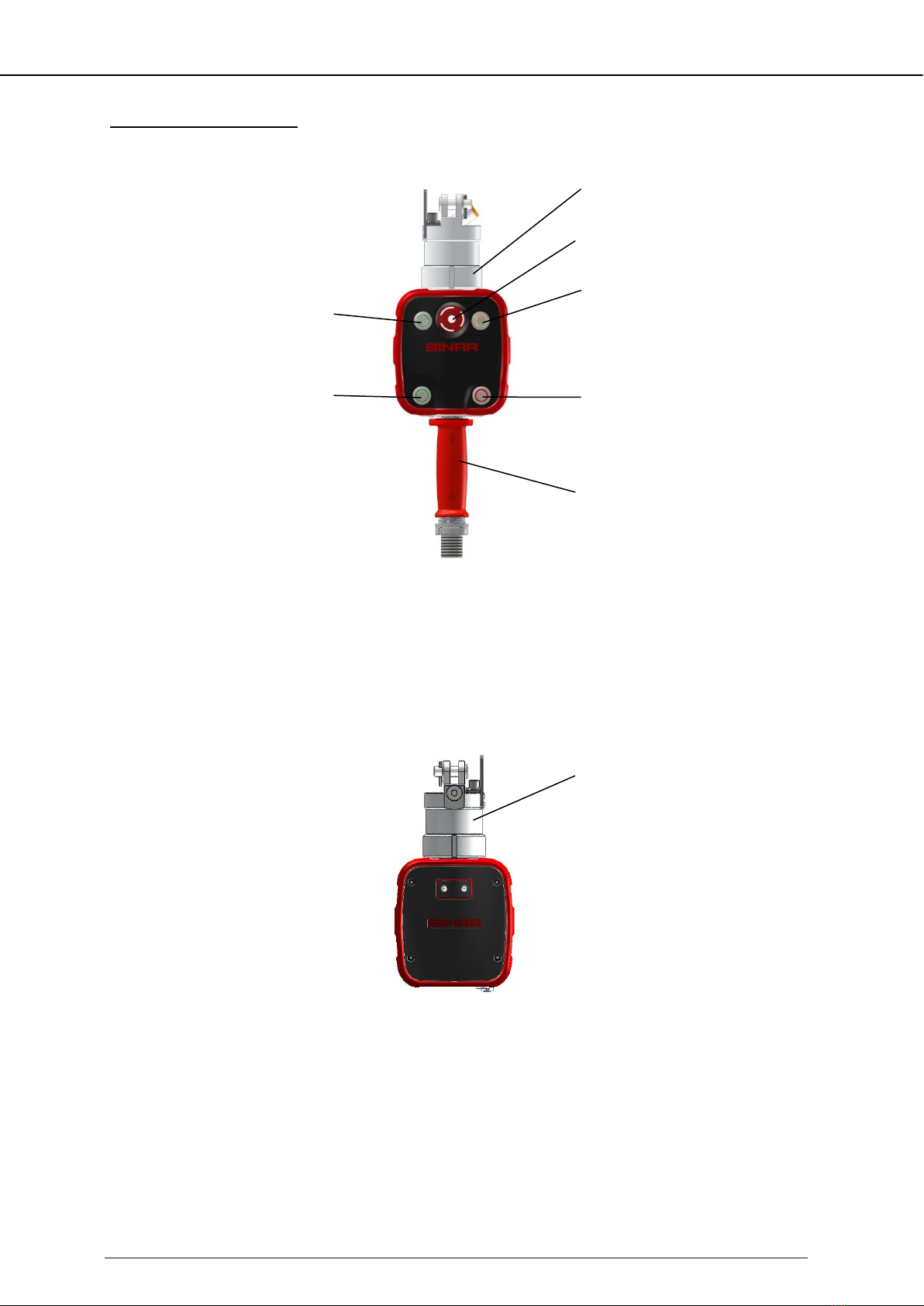
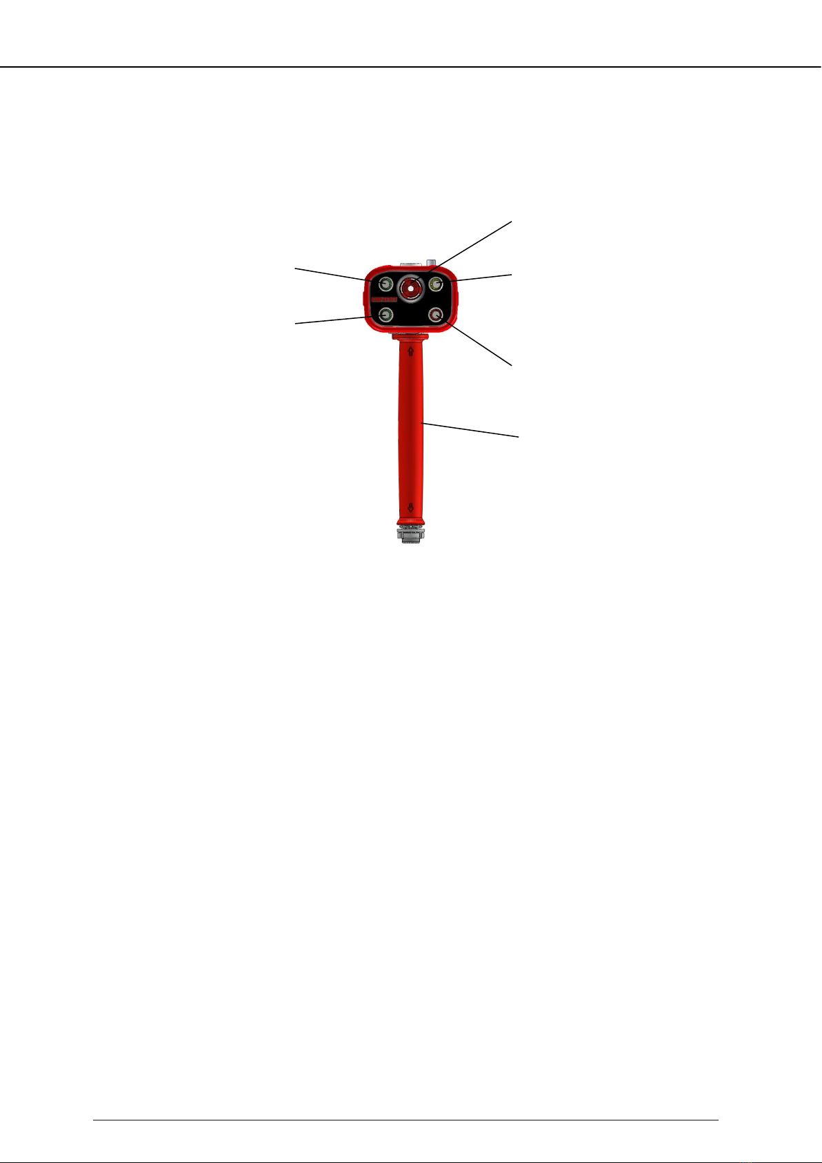
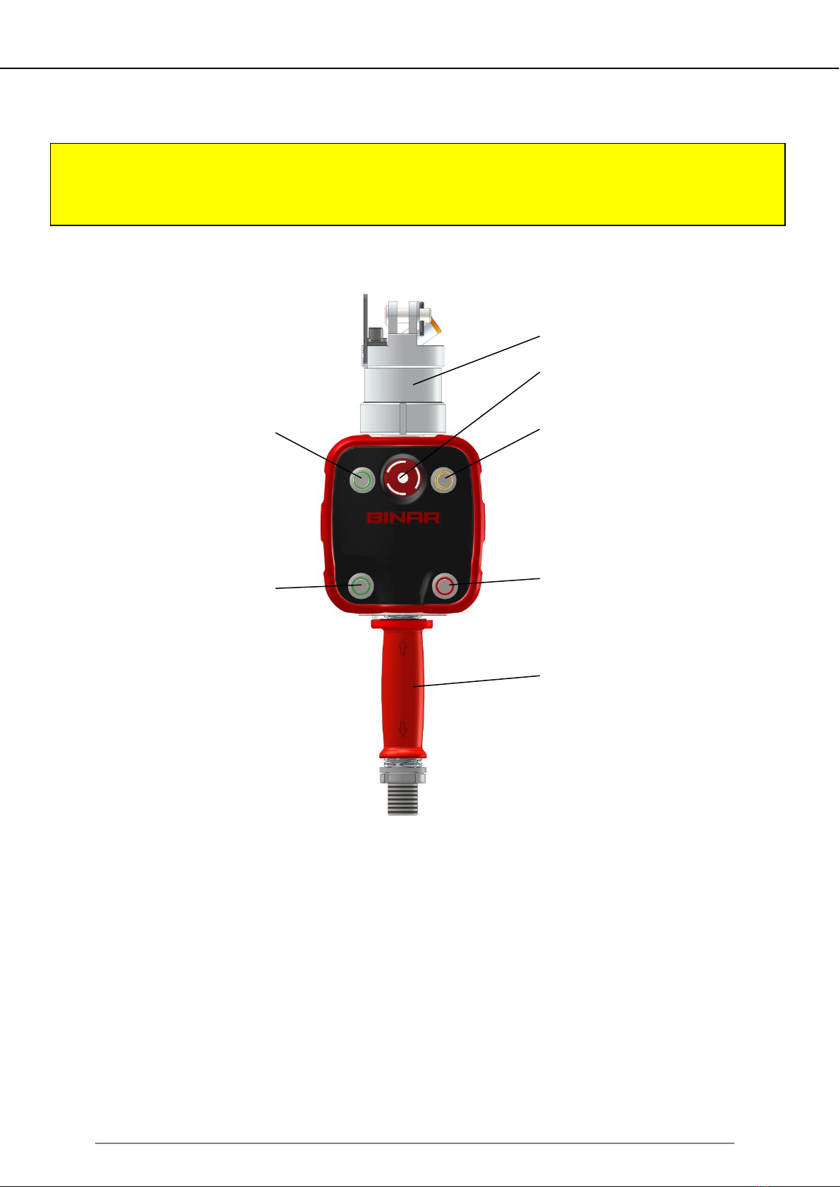
4.1 Control handle/External handle ................................................................................... 15
4.2 Emergency stop ............................................................................................................ 15
4.3 Function in handle mode.............................................................................................. 15
4.4 Function in full auto-balance mode.............................................................................. 16
4.5 Function –lifting device in limited auto-balance mode ............................................... 16
4.6 Before start................................................................................................................... 16
4.7 When starting............................................................................................................... 17
4.8 Performing a lift operation........................................................................................... 17
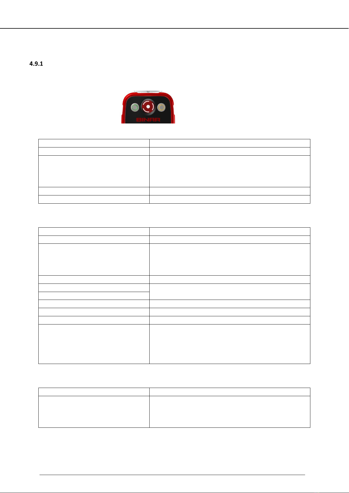
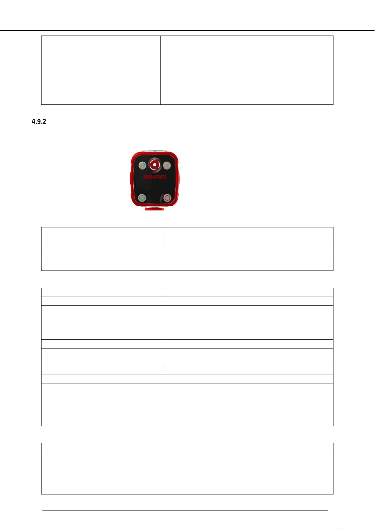
4.9 The LEDs functions on different types of control handles/external handles ............... 18
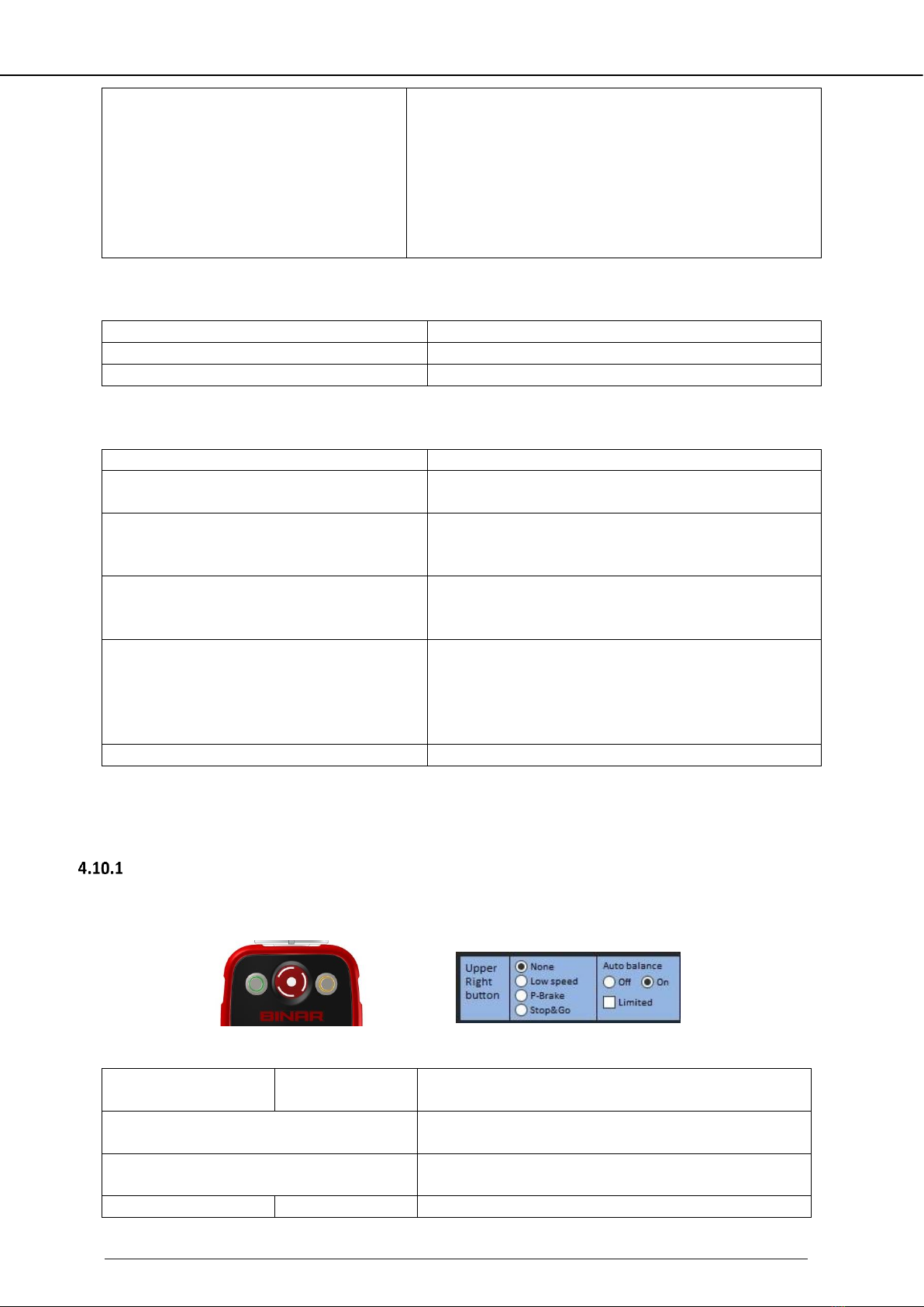
4.10 The buttons' functions on different types of control handles/external handles ......... 20
4.11 Other functions............................................................................................................. 23
4.12 Installation instructions when replacing the gripper.................................................... 24
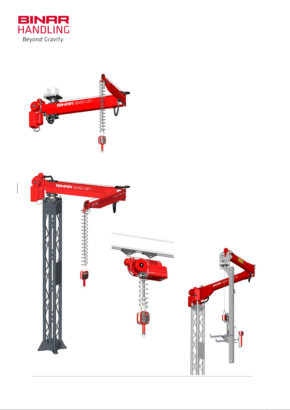
5. LIFTING DEVICE, GENERAL DESCRIPTION ............................................................................28
6. VARIANTS OF QUICK-LIFT ARM/QUICK-LIFT RAIL/QUICK-LIFT ARM TORQUE .....................29
6.1 QLA ............................................................................................................................... 29
6.2 QLR ............................................................................................................................... 29
7. ADVANCED USE / ILAB 3 PROGRAM ...................................................................................30
7.1 General ......................................................................................................................... 30
7.2 Program window .......................................................................................................... 31
7.3 Menu bar ...................................................................................................................... 32
7.4 Parameter window, “SETTINGS” .................................................................................. 36
7.5 Parameter window, “STATUS”...................................................................................... 38
7.6 Parameter window, “IN/OUT”...................................................................................... 39
7.7 Parameter window “ADVANCED”................................................................................. 39
7.8 I/O board, connection principle.................................................................................... 42
8. SPARE PARTS......................................................................................................................47
8.1 Spare parts, lifting device ............................................................................................. 47
8.2Spare parts, control handle/external handle/control box............................................ 48
8.3 Exploded view –Spare parts......................................................................................... 49
9. INSTRUCTIONS FOR INSTALLING SPARE PARTS...................................................................50
9.1 Safety instructions when working on the lifting device ............................................... 50
9.2 Installation of the cable drum guard ............................................................................ 50
9.3 Cutting the wire rope ................................................................................................... 50
9.4 Replacement of the spiral cable ................................................................................... 50
9.5 Replacement of the wire rope...................................................................................... 51
10. MAINTENANCE OF THE LIFTING DEVICE..............................................................................53
10.1 Safety instructions when working on the lifting device ............................................... 53
10.2 Skills requirements for maintenance personnel........................................................... 53
10.3 Daily inspection ............................................................................................................ 53
10.4 One month after installation ........................................................................................ 53
10.5 Quarterly maintenance ................................................................................................ 54
10.6 Maintenance every twelve months.............................................................................. 54
10.7 Replacement of the wire rope...................................................................................... 55
10.8 End effectors and adaptors .......................................................................................... 55
11.TROUBLESHOOTING ...........................................................................................................56
11.1 Troubleshooting –for operators .................................................................................. 56
11.2 Troubleshooting - Via iLab 3 and the control handle’s/external handle’s LEDs........... 56
11.3 The wire rope guide has run against the mechanical stop and has jammed. .............. 59
11.4 Wire rope drum is jammed........................................................................................... 60
Version: QLA QLR QLAT QLRT EN V.7.04i
Date: 20/09/2021
5 (106)
11.5 Wire rope jams when assembling a new wire rope ..................................................... 60
12. INSTALLATION QLA.............................................................................................................61
12.1 Lifting instructions ........................................................................................................ 61
12.2 Rotation stops and mechanical end stops.................................................................... 62
12.3 Concrete requirements ................................................................................................ 63
12.4 Installing the pillar........................................................................................................ 63
12.5 Pillar types .................................................................................................................... 64
12.6 Installation of QLA on pillars......................................................................................... 65
12.7 Installation of electricity, pneumatics and software QLA............................................. 68
12.8 Adjusting friction brakes............................................................................................... 70
12.9 Installation drawing QLA .............................................................................................. 71
13. INSTALLATION OF QLA OVERHEAD MOUNTED ...................................................................74
13.1 Lifting instructions........................................................................................................ 74
13.2 Rotation stops and mechanical end stops.................................................................... 75
13.3 Fastening requirements................................................................................................ 75
13.4 Mounting QLA Overhead Mounted.............................................................................. 76
13.5 Installation of electricity, pneumatics and software QLA Overhead Mounted ............ 77
13.6 Adjusting friction brakes............................................................................................... 77
13.7 Installation drawing QLA Overhead Mounted.............................................................. 78
14. INSTALLATION QLR.............................................................................................................81
14.1 Lifting instructions........................................................................................................ 81
14.2 Assembly....................................................................................................................... 82
14.3 Installation height......................................................................................................... 82
14.4 Suspension in the rail system ....................................................................................... 83
14.5 Installation of electricity, pneumatics and software QLA............................................. 84
14.6 Installation drawings .................................................................................................... 85
15. ASSEMBLY INSTRUCTIONS FOR PARTS................................................................................87
15.1 Assembly of control box on gripper ............................................................................. 87
15.2 Fitting the wire rope to the swivel ............................................................................... 88
16. TECHNICAL DATA................................................................................................................89
17. DECLARATION ....................................................................................................................92
18. APPENDICES .......................................................................................................................93
18.1 Register wiring diagram................................................................................................ 93
18.2 Wiring diagram –see separate Appendix..................................................................... 93
18.3 Inspection and maintenance reports ........................................................................... 95
19. QUICK START GUIDE...........................................................................................................106
This document is copyright protected and all rights belong to Binar Handling AB. This document may not, in
whole or in part, be copied, photocopied, or translated without prior written consent from Binar Handling AB.
This document contains information that is copyrighted and may not be used or imparted to third parties
without first obtaining the written permission of Binar Handling AB.
Binar Handling cannot be held accountable or liable for any inaccurate or incomplete information in this
document and reserves the right to introduce changes without prior notice.
Version: QLA QLR QLAT QLRT EN V.7.04i
Date: 20/09/2021
6 (106)
Electric and Air swivel
Emergency stop
Upper right pushbutton
with yellow LED
(can be perceived as orange)
Lower right pushbutton
with red LED
Grip/Release
Manoeuvre Handle for
up/down movement
Terminology/Designations
Control handle
Control box
Upper left pushbutton
with green LED
Lower left pushbutton
with green LED
Grip/Release
Electric and Air swivel
Version: QLA QLR QLAT QLRT EN V.7.04i
Date: 20/09/2021
7 (106)
Emergency stop
Upper right pushbutton
with yellow LED
(can be perceived as orange)
Lower right pushbutton
with red LED
Grip/Release
Manoeuvre Handle for
up/down movement
External handle
Upper left pushbutton
with green LED
Lower left pushbutton
with green LED
Grip/Release
Version: QLA QLR QLAT QLRT EN V.7.04i
Date: 20/09/2021
8 (106)
1. Delivery specification
General
Serial number lifting device:
Delivery week (year-week):
Lifting device
101100 QLA 50i
101101 QLA 50i
(Max lifting weight 50 kg, Arm length 3 m)
61090 Wire rope 7.5 m
(Max lifting weight 50 kg, Arm length 4 m)
61087 Wire rope 8.5 m
011637 Spiral cable 600 mm
23051 Spiral hose, air 16 turns
With deviation from standard
101102 QLA 100i
101103 QLA 100i
(Max lifting weight 100 kg, Arm length 3 m)
61090 Wire rope 7.5 m
(Max lifting weight 100 kg, Arm length 4 m)
60187 Wire rope 8.5 m
011637 Spiral cable 600 mm
23051 Spiral hose, air 16 turns
With deviation from standard
101104 QLA 100i
101105 QLA 200i
(Max lifting weight 100 kg, Arm length 5 m)
61092 Wire rope 9.5 m
(Max lifting weight 200 kg, Arm length 3 m)
61090 Wire rope 7.5 m
011637 Spiral cable 600 mm
23051 Spiral hose, air 16 turns
With deviation from standard
101106 QLA 200i
101107 QLA 200i
(Max lifting weight 200 kg, Arm length 4 m)
60187 Wire rope 8.5 m
(Max lifting weight 200 kg, Arm length 5 m)
61092 Wire rope 9.5 m
011637 Spiral cable 600 mm
23051 Spiral hose, air 16 turns
With deviation from standard
101108 QLA 300i
101109 QLA 300i
(Max lifting weight 300 kg, Arm length 3 m)
61090 Wire rope 7.5 m
(Max lifting weight 300 kg, Arm length 4 m)
60187 Wire rope 8.5 m
011637 Spiral cable 600 mm
23051 Spiral hose, air 16 turns
With deviation from standard
101200 QLR 50i
101201 QLR 125i
(Max lifting weight 50 kg)
60188 Wire rope 4.5 m
(Max lifting weight 125 kg)
60188 Wire rope 4.5 m
011637 Spiral cable 600 mm
23051 Spiral hose, air 16 turns
With deviation from standard
101202 QLR 200i
101203 QLR 300i
(Max lifting weight 200 kg)
60188 Wire rope 4.5 m
(Max lifting weight 300 kg)
60188 Wire rope 4.5 m
011637 Spiral cable 600 mm
23051 Spiral hose, air 16 turns
With deviation from standard
Delivery specification continues on the next page
Version: QLA QLR QLAT QLRT EN V.7.04i
Date: 20/09/2021
9 (106)
101130 QLAT 350S (Max lifting weight is depending on load case)
________ Wire rope, L= m
102097 Arm L1____________L2___________ mm
013132 Cable, L= m
102076 Torque unit L3___________________ mm
23014 Hose, L= m
ID256 Parameter Max load ________________ kg
101230 QLRT 350S (Max lifting weight is depending on load case)
________ Wire rope, L= m
102076 Torque unit L3___________________ mm
013132 Cable, L= m
ID256 Parameter Max load__________________ kg
23014 Hose, L= m
Delivery specification continues on the next page
101120 QLA 50i, Overhead Mounted
101122 QLA 100i, Overhead Mounted
(Max lifting weight 50 kg, Arm length 3 m)
61090 Wire rope 7.5 m
(Max lifting weight 100 kg, Arm length 3 m)
61090 Wire rope 7.5 m
011637 Spiral cable 600 mm
23051 Spiral hose, air 16 turns
With deviation from standard
101123 QLA 100i, Overhead Mounted
101124 QLA 100i, Overhead Mounted
(Max lifting weight 100 kg, Arm length 4 m)
60187 Wire rope 8.5 m
(Max lyftvikt 100 kg, Armlängd 5 m)
61092 Vajer 9.5 m
011637 Spiral cable 600 mm
23051 Spiral hose, air 16 turns
With deviation from standard
101125 QLA 200i, Overhead Mounted
(Max lyftvikt 200 kg, Armlängd 3 m)
61090 Wire rope 7.5 m
011637 Spiral cable 600 mm
23051 Spiral hose, air 16 turns
With deviation from standard
Version: QLA QLR QLAT QLRT EN V.7.04i
Date: 20/09/2021
10 (106)
Options Quick-Lift Arm
Middle link
Pneumatic brakes
Options Quick-Lift Rail
Laser beam, distance sensor
Pneumatic brakes
Suspension
Without suspension
QLA 50i, QLA 100i, QLA 200i (3 m), QLAT 350S
QLA 200i (4 m and 5 m), QLA 300i
013811 Pillar, length 3000 mm
013814 Pillar, length 3000 mm
013812 Pillar, special length: ________mm
013815 Pillar, special length: _______mm
QLR 50i, QLR 125i
QLR 200i, QLR 300i
Suspension for rail system Ø16 mm
Suspension for rail system Ø20 mm
Deviation from standard
Wire rope
_____________ L=___________ m
Spiral cable
011973 300 mm
011639 1000 mm
011972 400 mm
011640 1200 mm
011638 800 mm
013030 L=________mm
Spiral hose, air
_________pcs. Turns
Miscellaneous
Control handle, Part No.
1014000420
L=420 mm
Control handle, for mechanical grippers
1014000575
L=575 mm
Control handle, for mechanical grippers
1014000875
L=875 mm
Control handle, for mechanical grippers
1014030420
L=420 mm
Control handle, with vacuum ejector
1014030575
L=575 mm
Control handle, with vacuum ejector
1014030875
L=875 mm
Control handle, with vacuum ejector
101402
L=420 mm
Control handle, with pneumatic cylinder
1014010420
L=420 mm
Control handle, with pneumatic 5/2 valve
1014010575
L=575 mm
Control handle, with pneumatic 5/2 valve
1014010875
L=875 mm
Control handle, with pneumatic 5/2 valve
Control box, Part No.
101420
Control box, for mechanical grippers
101421
Control box with pneumatic 5/2 valve
101422
Control box for external pneumatics
External handle, Part No.
1014100245
External handle, L = 245
1014100400
External handle, L = 400
1014100700
External handle, L = 700
Delivery specification continues on the next page
Version: QLA QLR QLAT QLRT EN V.7.04i
Date: 20/09/2021
11 (106)
Project Handle (with deviation from standard)
This documentation as well as a USB memory stick containing the iLab 3 program is included in the delivery
of a lifting device from Binar Handling AB. The USB memory stick can be found at the back of this
documentation.
Version: QLA QLR QLAT QLRT EN V.7.04i
Date: 20/09/2021
12 (106)
2. Warranty
Binar Handling AB provides a 24-month warranty, at a maximum of two working shifts.
The warranty on new spare parts is for 12 months.
The warranty does not apply to wear parts. See chapter 9.
The warranty is void if the equipment is damaged in conjunction with opening of the covers. Binar
Handling AB determines all warranty matters.
The lifting device contains many safety critical and ESD sensitive components, and for this reason
anyone performing maintenance and refurbishment must possess the requisite knowledge.
Version: QLA QLR QLAT QLRT EN V.7.04i
Date: 20/09/2021
13 (106)
3. General safety instructions
Persons operating the lifting device must study and adhere to this documentation.
In order to use the lifting device the following general safety instructions apply:
•Prior to operating the lifting device for the first time, personnel with good knowledge of the lifting
device must demonstrate how it works.
•The lifting device must not be used to lift people.
•The lifting device must not be driven towards another person as this can pose a risk of injury.
•Do not walk under suspended loads, nor shall any part of the body be under a suspended load or
in an area where the suspended load can tip over.
•Protective footwear must be worn.
•The lifting device must not be used for lifting where a falling load could damage/destroy pipes or
wiring that could cause the discharge of flammable, toxic, hot, corrosive gases or liquids.
•The lifting device must not be used to lift molten and hot liquid loads.
•The lifting device must not be used to lift objects, including the gripper, that weigh more than the
lifting device’s maximum capacity, see “Delivery specification” (chapter 1).
•No body parts should be inserted between the wire rope, cable harness or air hose. Nor should
they be wrapped around a body part.
•The lifting device may only be used for vertical lifting, horizontal movement is performed after
lifting. It is not permitted to pull or drag objects horizontally by means of the lifting device.
•The lifting device must not be used to lift objects that are secured.
•Avoid knocking/bumping a raised object.
•Never leave the lifting device unattended with a suspended load.
•The gripper or control handle must not be raised by hand; this is to ensure that the wire-rope
does not become slack which can result in the wire rope becoming tangled.
•Be aware of any abnormal noise emanating from the lifting device. In the event of noise contact
qualified service personnel.
•Maintenance must be performed at the recommended intervals, see “Maintenance of the lifting
device” (chapter 10).
•The lifting device is designed for indoor use.
•The area that the lifting device serves must have adequate lighting.
•The area that lifting device serves must be free of objects on the floor that give rise to a risk of
tripping.
•The maximum angle between the wire rope and the swivel’s centre line is 5 degrees.
•The control handle/external handle must not be released so that it swings in towards something,
this can damage e.g. the emergency stop button.
•Before any cover on the lifting device is opened, the power suply supply must be switched off.
•The lifting device contains many safety critical and ESD sensitive components and for this reason
anyone performing maintenance must possess the requisite knowledge.
•The arms on the lifting device must not be buckled or damaged. If the arms show significant
damage, Binar Handling AB must be contacted for advice on whether the arms must be replaced
to ensure that continued safe functionality is retained.
3.1 Safety features –lifting device
•Anti-drop brake - the lifting device has integrated an anti-drop brake. In the event of a power
failure the load will not fall, but is held safely in place. All functionality returns once the power to
the lifting device is restored.
•Dead man’s handle - this function means that as soon as the operator releases the manoeuvre
handle, the lifting device stops in position by itself.
•Emergency stop - the lifting device has an emergency stop mounted on the control handle or on
the external handle.
Version: QLA QLR QLAT QLRT EN V.7.04i
Date: 20/09/2021
14 (106)
•Programmed stop - the lifting device has programmable stops for the top and bottom positions.
•Mechanical stop - the lifting device has a mechanical end position stop, which means the wire
rope cannot be completely wound off the wire rope drum. There is also a stop in the other
direction to prevent too much wire rope being wound onto the wire rope drum. The lifting device
stops completely and after a run loose procedure it is possible to operate normally again (see
chapter 11.3).
•Control - it is possible to control the lifting device’s functions via PLC in the supplied PC software
iLab 3 for increased functionality and safety.
•The lifting device must not be subjected to lurching movements. If this occurs, the lifting device
will enter power save mode, which is logged.
Version: QLA QLR QLAT QLRT EN V.7.04i
Date: 20/09/2021
15 (106)
4. Operating description
4.1 Control handle/External handle
Example –control handle with four pushbuttons
4.2 Emergency stop
In the event of possible danger, the operator can use the emergency stop on the control
handle/external handle to immediately stop the lifting device.
Any external movements, such as rotation or tilting, must have a “hold-to-run” function,
according to EN 13155+A2:2009. For correct connection, see chapter 7.8.2.
Turn the emergency stop button on the control handle or external handle to reset. The lifting device
then automatically performs a brake test before returning to normal mode.
4.3 Function in handle mode
The manoeuvre handle detects the force from the hand and converts the signal to a lifting speed in
the wire rope. Only minimal operating force is required irrespective of the size of the load.
When the grip on the manoeuvre handle is released the lifting device stops its vertical motion. The
horizontal movement slows. Avoid jerky movements.
Electric and Air swivel
Emergency stop
Upper right pushbutton
with yellow LED
(can be perceived as orange)
Lower right pushbutton
with red LED
Manoeuvre Handle for
up/down movement
Upper left pushbutton
with green LED
Lower left pushbutton
with green LED
NOTE!
Make sure the power suply supply to the lifting device is switched off when replacing
the gripper!
Version: QLA QLR QLAT QLRT EN V.7.04i
Date: 20/09/2021
16 (106)
4.4 Function in full auto-balance mode
The lifting device can serve as a balance lift in so-called auto-balance mode. Both hands can then be
used to manoeuvre the load, both vertically and horizontally.
In auto-balance mode the lifting device’s load cell detects the weight of the lift object; when the
operator lifts the lift object with his hands, the lifting device interprets this as an up signal and lifts up
the lift object and vice versa when the operator presses the lift object down.
The function can be activated and deactivated by pressing and holding the top right button for two
seconds.
A yellow LED around the button lights when auto-balance mode is active.
The lifting device’s load cell needs to detect a stable weight for about one second in order to activate
auto-balance.
It is important that you do not touch the lift object during weight measurement.
If you touch the manoeuvre handle, the lifting device immediately switches to handle mode.
Full auto-balance mode is recommended primarily when the lifting device has to lift parts that do not
require as much precision in the deposit position.
4.5 Function –lifting device in limited auto-balance mode
This function works in the same way as the full auto-balance mode described above, but has an
inherent limitation.
This limitation requires the lifting device to detect the balanced weight for 150 milliseconds before it
can reverse direction from up to down and vice versa. If this condition is not met, the speed is limited
to 3 mm/s, which is often perceived as being stationary.
This limitation makes it easier for example to position the lift object in a hole without the lift object
bouncing up if alignment is not precise.
This limitation makes it even easier to e.g. fit a lift object on horizontal studs without the lifting
device tending to jerk the lift object.
In iLab 3, you can choose between Full and Limited auto-balance modes. See "iLab 3" chapter 7.4.4
Limited auto-balance mode is recommended, for example, when the lifting device is to be used for
assembling parts.
4.6 Before start
The lifting device must be checked once a day, ideally at the beginning of the shift. This is to ensure
the integrity and safety of the lifting device. Once you have checked the four points, fill in the report
for daily inspection, see "Appendices" in chapter 18. If no faults are detected, the lifting device is
ready to be used. If any faults are detected, notify your supervisor immediately.
The points to be checked are:
•That the wire rope is undamaged.
•That the control handle or the control box and external handle are undamaged.
•That the spiral cable and compressed air hose are undamaged.
•No noise occurs when running up and down respectively. Be extremely attentive to creaking
sounds, which could be a sign of wire rope tangle on the wire rope drum.
Version: QLA QLR QLAT QLRT EN V.7.04i
Date: 20/09/2021
17 (106)
4.7 When starting
•If the power suply to the lifting device has been switched off, wait at least 10 seconds before
turning the power suply back on.
•The green LED next to the top left pushbutton will flash if the lifting device has entered power
save mode. You then need to activate the lifting device. Do this by pressing the top left button.
The lifting device then releases the anti-fall brake and performs a brake test. The LED then
switches to a fixed green light.
•Start-up time following power saving mode is about 3 seconds.
•Start-up time following emergency stop is about 10 seconds.
•The start-up time after a power failure is about 25 seconds.
•NOTE! If the lifting device does not start, see “Troubleshooting”, chapter 11.
•If the lifting device has been stopped via the emergency stop, a yellow LED flashes.
4.8 Performing a lift operation
•Check that the wire rope is not slack.
•The control handle or gripper must never be lifted by hand so that the wire rope is slack.
•Check the grip on the lift object is secure.
•Slowly lift up the object from its position.
•Move the lift object to the designated position. Perform the movement at a speed where
control of the lifting device and gripper/load is maintained.
•Avoid quick, jerky movements during the entire lift operation.
NOTE! During up or down run commands towards the top or bottom position for more than 10
seconds, the lift shuts down itself.
Version: QLA QLR QLAT QLRT EN V.7.04i
Date: 20/09/2021
18 (106)
4.9 The LEDs functions on different types of control handles/external handles
Control handle for mechanical grippers
On a control handle of the type Control handle for mechanical grippers there are two LEDs around
the buttons.
Around the upper left button there is a green LED that normally has the following function:
Function
Description
Short flashes
The lifting device is in power save mode.
Unlit
The lifting device is not powered up, has been stopped via
the emergency stop or it has a fault.
For application software V3.00.99 or older, it is off as the
lifting device is shut down by the monitoring functions.
Fixed light
The lifting device is in normal mode.
Very rapid flashing
The lifting device is busy initializing (start-up).
Around the upper right button there is a yellow LED that normally has the following function:
Function
Description
Unlit
The lifting device is in handle mode.
Fixed light
The lifting device is in auto-balance mode and is balanced
(LED is off while the lifting device detects the load). See
also “Steady light with intermittent interruptions every
two seconds”
Slow single flashing
Emergency stop activated.
Constant single flashing
The lifting device has a basic fault, See “Troubleshooting”
The lifting device has a serious fault, chapter 11.2.1
Constant double flashing
A single flash
The lifting device is set to low speed.
A double flash
The lifting device is set to high speed.
Very rapid flashing
CAN traffic stopped (possibly by the monitoring functions).
Steady light with intermittent
interruptions every two seconds.
Parking brake on.
Note! Even if the lifting device is in auto balance mode, the
light indicator for “Parking brake on” is still displayed next
to the top right-hand button.
Both the upper green LED and the yellow LED may flash or be lit simultaneously:
Function
Description
Quick flashing on both green and
yellow LEDs
The lifting device is in a mode to automatically set the
“Minimum pulling force” and “Weight limit for
grip/release”. Do not touch the lifting device in this mode.
Also see "iLab 3" chapter 7.4.5
Version: QLA QLR QLAT QLRT EN V.7.04i
Date: 20/09/2021
19 (106)
Fixed green LED and quick flashing
yellow LED
The lifting device has an error, but it can be run in a
limited way to solve the problem.
Examples of errors:
•Gripper has moved outside of the specified working
range on the vertical axis. Moving back to the work
area is permitted.
•The lifting device is overloaded. Only running down is
permitted to unload the gripper.
Valve handle, Vacuum handle, Cylinder handle and all external handles
On a control handle of the type Valve handle, Vacuum handle, Cylinder handle and all external
handles there are four LEDs around the buttons.
Around the upper left button there is a green LED that normally has the following function:
Function
Description
Short flashes
The lifting device is in power save mode.
Unlit
The lifting device is not powered up, has been stopped
via the emergency stop or it has a fault.
Fixed light
The lifting device is in normal mode.
Around the upper right button there is a yellow LED that normally has the following function:
Function
Description
Unlit
The lifting device is in handle mode.
Fixed light
The lifting device is in auto-balance mode and is
balanced (LED is off while the lifting device detects the
load). See also “Steady light with intermittent
interruptions every two seconds”
Slow single flashing
Emergency stop activated.
Constant single flashing
The lifting device has a basic fault, See “Troubleshooting”
The lifting device has a serious fault, chapter 11.2.1
Constant double flashing
A single flash
The lifting device is set to low speed.
A double flash
The lifting device is set to high speed.
Steady light with intermittent
interruptions every two seconds.
Parking brake on.
Note! Even if the lifting device is in auto balance mode,
the light indicator for “Parking brake on” is still displayed
next to the top right-hand button.
Both the upper green LED and the yellow LED may flash or be lit simultaneously:
Function
Description
Quick flashing on both green and yellow
LEDs
The lifting device is in a mode to automatically set the
“Minimum pulling force” and “Weight limit for
grip/release”. Do not touch the lifting device in this
mode.
Also see "iLab 3" chapter 7.4.5
Version: QLA QLR QLAT QLRT EN V.7.04i
Date: 20/09/2021
20 (106)
Fixed green LED and quick flashing yellow
LED
The lifting device has an error, but it can be run in a
limited way to solve the problem.
Examples of errors:
•Gripper has moved outside of the specified working
range on the vertical axis. Moving back to the work
area is permitted.
•The lifting device is overloaded. Only running down is
permitted to unload the gripper.
Around the lower left button there is a green LED that normally has the following function:
Function
Description
Unlit
Grip or release not permitted.
Fixed light
Grip or release permitted.
Around the lower right button there is a red LED that normally has the following function:
Function
Description
Unlit
The gripper on the lift object is OK, this assumes that
the “Stop-up” function is used. See chapter 7.7.4
Constant single flashing (pneumatic gripper)
Warning for incorrect grip by the pneumatic gripper
with connected sensor for stop-up function.
Accompanied by an audio signal.
Constant single flashing (vacuum gripper)
Warning for incorrect grip by the vacuum gripper with
connected sensor for low vacuum level. Accompanied
by an audio signal.
Constant single flashing (magnetic gripper)
Warning that the magnet is not turned around fully to
the grip position. Accompanied by an audio signal.
Used when the function “Magnet sequence” is used in
combination with sensor for the position of the
magnet.
Fixed light (magnetic gripper)
Warning that the magnet is activated.
4.10 The buttons' functions on different types of control handles/external handles
Control handle for mechanical grippers
On a control handle of the type Control handle for mechanical grippers there are two buttons.
The upper left button normally has the following function:
Function
Possible sub-
function
Description
A short press
Switches between power save mode and operating
mode
Press and hold the button for more than
10 seconds
Activates top and bottom position setting.
(Also see chapter 7.3.5).
The lifting speed is
A short press
Set top position.

This manual suits for next models

3

Other BINAR Lifting System manuals

BINAR NEO 30 User manual

BINAR

BINAR NEO 30 User manual

BINAR NEO 30 User manual

BINAR

BINAR NEO 30 User manual

BINAR NEO30 1400 EL Instruction Manual

BINAR

BINAR NEO30 1400 EL Instruction Manual

Popular Lifting System manuals by other brands

Garage Smart Hard Top Lifter Installation and operation guide

Garage Smart

Garage Smart Hard Top Lifter Installation and operation guide

vimec Easy Lift Assembly instructions

vimec

vimec Easy Lift Assembly instructions

SPIDER SC1500 Checklist and operations manual

SPIDER

SPIDER SC1500 Checklist and operations manual

Plymovent Balancer Series user manual

Plymovent

Plymovent Balancer Series user manual

Lift King Pro King 9XLT Installation & operation manual

Lift King

Lift King Pro King 9XLT Installation & operation manual

Pulseroller PDU-90 instruction manual

Pulseroller

Pulseroller PDU-90 instruction manual

MAHA ZS SQUARE II 3.5 Original operating instructions

MAHA

MAHA ZS SQUARE II 3.5 Original operating instructions

Alutech PSL Series Mounting instruction

Alutech

Alutech PSL Series Mounting instruction

Upright TM12 Service & parts manual

Upright

Upright TM12 Service & parts manual

JLG 4394RT Operation and safety manual

JLG

JLG 4394RT Operation and safety manual

morse 525-N-114 Operator's manual

morse

morse 525-N-114 Operator's manual

LGMG AS0808 user manual

LGMG

LGMG AS0808 user manual

Launch TLT440 installation manual

Launch

Launch TLT440 installation manual

Reid SwiftLift operating instructions

Reid

Reid SwiftLift operating instructions

pewag levo hook LH5 Original operating manual

pewag

pewag levo hook LH5 Original operating manual

Sealey MC480.V3 instructions

Sealey

Sealey MC480.V3 instructions

Genie Z-45/25 Operator's manual

Genie

Genie Z-45/25 Operator's manual

KITO ER2-075S Owner's manual supplement

KITO

KITO ER2-075S Owner's manual supplement

manuals.online logo
manuals.online logoBrands
  • About & Mission
  • Contact us
  • Privacy Policy
  • Terms and Conditions

Copyright 2025 Manuals.Online. All Rights Reserved.