Binder 8012-0556 User manual

Version 12/2008 Art. Nr. 7001-0101
Anleitung zum Anschluss
Schnittstellenwandler RS 232/RS422
für APT-COM™
Installation Manual
RS 232/RS422 Interface Converter
for APT-COM™
Manual de conexión
del convertidor de interfaz RS 232/RS422
para APT-COM™
Инструкция по подсоединению
конвертера интерфейсов RS232/RS422
для APT-COM™
BINDER GmbH
Address Post office box 102
D-78502 Tuttlingen
Tel. +49 7462 2005 0
Fax +49 7462 2005 100
Internet http://www.binder-world.com
Service Hotline +49 7462 2005 555
Service Fax +49 7462 2005 93 555
Service Hotline USA +1 866 885 9794 or +1 631 224 4340
Service Hotline Spain +34 9492 677 23
Service Hotline Asia Pacific +852 39070500 or +852 39070503
Service Hotline Russia and CIS +7 495 98815 17
RUS

Anschluss des Konverters RS232/RS422 12/2008 Seite 2/17
D
Anleitung zum Anschluss des Schnittstellenwandlers
RS232/RS422
Inhalt
1. Hinweis zu dieser Anleitung ................................................................................................ 2
2. Bestimmungsgemäßer Gebrauch ....................................................................................... 2
3. Gerätebeschreibung............................................................................................................ 3
4. Lieferumfang des Sets Schnittstellenwandler RS232/RS422.............................................. 4
5. Vernetzung .......................................................................................................................... 4
5.1. Bus-Terminierung................................................................................................................ 5
6. Service ................................................................................................................................ 5
1. Hinweis zu dieser Anleitung
Diese Anschlussanleitung enthält eine kurze Beschreibung über Anschluss und Installation des
Schnittstellenwandlers RS232/RS422. Es wird dabei vorausgesetzt, dass der
Schnittstellenwandler über die BINDER GmbH bezogen wurde und deshalb intern die richtigen
Einstellungen bereits getroffen sind. Ferner wird davon ausgegangen, dass nur Geräte und
Kabel der BINDER GmbH eingesetzt werden, die speziell für diesen Zweck angeboten werden.
Um bei Bedarf andere Möglichkeiten nutzen zu können, die der Schnittstellenwandler
RS232/RS422 bietet, liegt neben dieser Anleitung auch die Originalanleitung des Herstellers,
der Fa. W & T bei.
2. Bestimmungsgemäßer Gebrauch
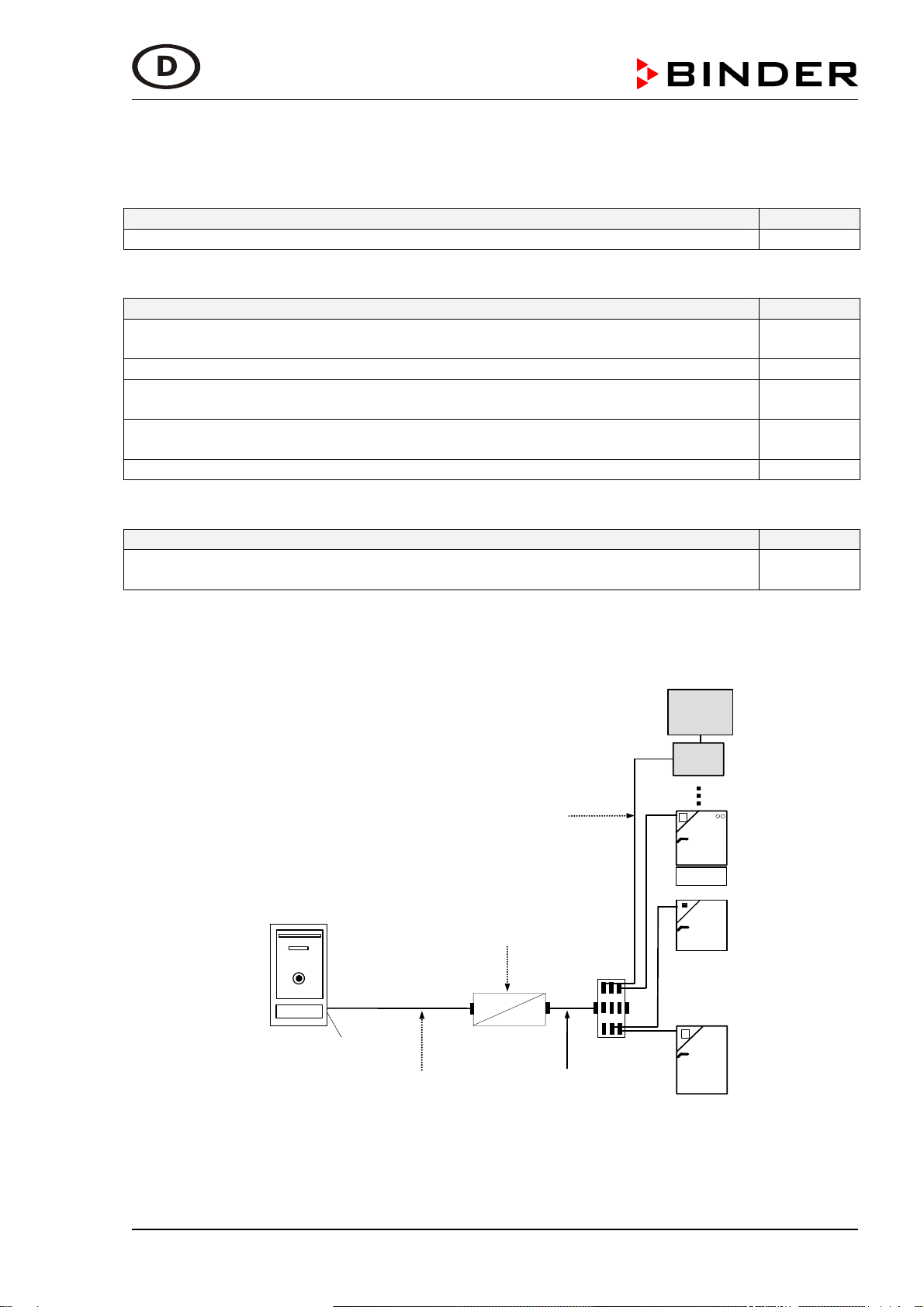
Der Schnittstellenwandler RS232/RS422 ist geeignet, um Temperaturschränke mit RS422-
Schnittstelle, ebenso Messgeräte und die Alarmbox AB01 der BINDER GmbH über die RS232
Schnittstelle des Computers zu vernetzen.
An einem beliebigen PC kann die Kommunikationssoftware APT-COM™der BINDER GmbH
oder ein vorhandenes Datenerfassungssystem eingesetzt werden, um die an das RS422-
Netzwerk angeschlossenen Temperaturschränke zu steuern und deren Messdaten zu
empfangen und zu speichern.

Anschluss des Konverters RS232/RS422 12/2008 Seite 3/17
D
3. Gerätebeschreibung
Der Schnittstellenwandler RS232/RS422 ist ein eigenständiges elektrisches Betriebsmittel mit
externer Spannungsversorgung über ein 24V AC Steckernetzteil. Es kann lose verlegt oder auf
Klemmprofilschiene in Verteilerkästen montiert werden. Über interne DIP-Schalter und
Steckbrücken können verschiedene Betriebsarten eingestellt werden. Die für den Betrieb von
Temperaturschränken der BINDER GmbH notwendigen Einstellungen wurden von der BINDER
GmbH bereits voreingestellt.
Die Betriebsart für BINDER Geräte nach Angabe der original W&T Betriebsanleitung ist
„RS422, RS 485, 4-Draht-Bus-Master“. Standard-Einstellung für BINDER Geräte siehe Abb. 3.
Der Anschluss an die RS232-Schnittstelle erfolgt über ein Null-Modem-Kabel. Der Anschluss an
einen Temperaturschrank der BINDER GmbH oder an einen Steckverteiler zum Anschluss
mehrerer Temperaturschränke erfolgt an einer 9-poligen Sub-D Buchse über ein spezielles
Kabel. Beide Anschlusskabel und das Steckernetzteil sind im Lieferumfang enthalten.
Der/die dort angeschlossenen Temperaturschränke werden über diese COM-Schnittstelle und
die Adresse angesprochen, die im Regler jedes Temperaturschrankes individuell einstellbar ist.
Abbildung 1: Angeschlossener Schnittstellenwandler

Anschluss des Konverters RS232/RS422 12/2008 Seite 4/17
D
4. Lieferumfang des Sets Schnittstellenwandler RS232/RS422
Gesamtes Set
Beschreibung Art.Nr.
Set Schnittstellenwandler RS232/RS422 8012-0556
Bestandteile des Sets:
Beschreibung Art.Nr.
Schnittstellenwandler RS232/RS422 mit Originalanleitung des Herstellers W&T
(nur bei Problemen mit der Inbetriebnahme benötigt)
5021-0022
Null-Modem-Kabel 3 m zum Anschluss an die RS232 Schnittstelle 5023-0115
Anschlusskabel 5m für Verbindung vom Schnittstellenwandler zu einem
einzelnen Gerät oder zu einem Steckverteiler RS422 von BINDER
5023-0095
Adapter SUB-D 25-Pole Stifte-Stifte (Gender changer) (nicht benötigt bei
Geräteanschluss über den BINDER Steckverteiler RS422)
5024-0062
Anleitung Anschluss Schnittstellenwandler RS232/RS422 7001-0101
Option
Beschreibung Art.Nr.
Verlängerungskabel 50m für Verbindung vom Anschlusskabel 5m zu einem
einzelnen Gerät oder zu einem Steckverteiler RS422 von BINDER
5023-0117
5. Vernetzung
Alle Temperaturschränke werden über den gleichen Schnittstellenwandler RS232/RS422
angeschlossen.
2
1
3
Schnittstelle RS232
30
Kabel 15m
Art. Nr. 5023-0036
CB
Alarm
Box
BD
ED
FD
KBF
Telefon-
wählgerät
APT.line
®
(E2)
Schnittstellenwandler
RS232 / RS422
RS232
RS422
Null-Modem-Kabel 3m
Art. Nr. 5023-0115
Kabel 5m
Art. Nr. 5023-0095
optional: Verlängerungskabel
Art. Nr. 5023-0117
Steuerungs- und
Überwachungs-PC
z.B. mit APT-COM
PC
Abbildung 2: Vernetzung über Schnittstellenwandler RS232/RS422
Das optionale Verlängerungskabel 50m (5023-0117) kann zusätzlich hinter das 5m Kabel
(5023-0095) angeschlossen werden.

Anschluss des Konverters RS232/RS422 12/2008 Seite 5/17
D
Der Schnittstellenwandler RS232/RS422 ist nun vollständig installiert. Die Temperaturschränke
werden in der Kommunikationssoftware APT-COM™nun mit der COM-Nummer angemeldet,
die für den Schnittstellenwandler RS232/RS422, an dem sie alle zusammen angeschlossen
sind, vergeben wurde. Die für die eindeutige Identifizierung der Temperaturschränke
notwendige Geräteadresse muss in jedem Regler eines jeden Temperaturschrankes oder
Messgerätes individuell und einmalig im Netzwerk von Hand eingetragen werden. Die
Beschreibung hierzu findet sich in der Betriebsanleitung des jeweiligen Gerätes mit RS422-
Schnittstelle.
5.1. Bus-Terminierung
Die empfohlene Betriebsart des Schnittstellenwandlers für den Anschluss von BINDER Geräten
ist mit aktivierter Terminierung (BINDER Werkseinstellung).
Da manche Regler, z.B. R3, R 3.1, über eine interne Terminierung verfügen, sind bei
Kombination unterschiedlicher Reglervarianten Kommunikationsfehler möglich, die in der APT-
COM™als „Timeout“ oder „CRC Fehler“ gemeldet werden. Daher kann es nötig sein, die
Terminierung im Schnittstellenwandler auszuschalten.
Um die Terminierung auszuschalten, setzen Sie die DIP Schalter 6 und 7 im
Schnittstellenwandler auf Off. Die korrekte Einstellung kann gefahrlos ausprobiert werden, es
besteht zu keiner Zeit die Möglichkeit, Regler oder Schnittstellenwandler zu beschädigen.
Abbildung 3: Einstellung der Terminierung über DIP Schalter 6 und 7
6. Service
Service Hotline +49 7462 2005 555
Service Fax +49 7462 2005 93 555
Service Hotline USA +1 866 885 9794 oder +1 631 224 4340
Service Hotline Spanien +34 9492 677 23
Service Hotline Asia Pacific +852 39070500 oder +852 39070503
Service Hotline Russland und GUS +7 495 98815 17

Connection of converter RS232/RS422 12/2008 Page 6/17
GB
Installation Manual for RS232/RS422 Interface Converter
Content
1. Information notice regarding the manual............................................................................. 6
2. Intended use........................................................................................................................ 6
3. Unit description.................................................................................................................... 7
4. Scope of delivery of Interface Converter RS232/RS422 set ............................................... 8
5. Networking .......................................................................................................................... 8
5.1. Bus termination ................................................................................................................... 9
6. Service ................................................................................................................................ 9
1. Information notice regarding the manual
This installation manual contains a short description how to connect and install the
RS232/RS422 Interface Converter and the drivers needed. It is expected that the Interface
Converter has peen purchased at the BINDER GmbH and thus the correct internal settings
have already been carried out. It is also assumed that only devices and cables of the BINDER
GmbH offered specially for this purpose will be used. To allow also different kinds of use offered
by the RS232/RS422 Interface Converter, we include next to this manual also the original
operation manual of the producer W & T.
2. Intended use
The RS232/RS422 Interface Converter is suitable to network temperature chambers with
RS422 interface, measurement devices, and the Alarm Box AB01 of the BINDER GmbH via the
RS232 computer interface.
At any computer the communication software APT-COM™of the BINDER GmbH or an existing
data acquisition system can be used to control the temperature chambers connected to the
RS422 network and to receive and save the chamber measurement data.

Connection of converter RS232/RS422 12/2008 Page 7/17
GB
3. Unit description
The RS232/RS422 Interface Converter is independent electrical equipment with external power
supply via a 24V AC power supply unit. It can be loosely installed or mounted to clamping profile
bars in distributor boxes. By internal DIP switches and plug bridges different operational modes
can be set. The settings necessary for operating temperature chambers of the BINDER GmbH
have already been pre-set by the BINDER GmbH.
The operating mode for BINDER chambers according to the original W&T user manual is
“RS422, RS 485, 4-wire-bus-master”. For standard settings for BINDER chambers refer to
Figure 3.
The connection to a RS232 interface is established using a Zero-Modem cable. The connection
to a temperature chamber of the BINDER GmbH or to a plug distributor for connecting several
temperature chambers is established using a 9-poles Sub-D socket and a special cable. Both
connection cables and the power supply unit are included with the scope of delivery.
The connected temperature chamber(s) are addressed via this COM interface and the address
that can be individually adjusted at each chamber controller.
Figure 1: Connected Interface Converter

Connection of converter RS232/RS422 12/2008 Page 8/17
GB
4. Scope of delivery of Interface Converter RS232/RS422 set
Complete set
Description Art.No.
Set Interface Converter RS232/RS422 8012-0556
Set parts:
Description Art.No.
Interface Converter RS232/RS422 with original description of producer W & T
(only needed in case of problems during start-up)
5021-0022
Zero-Modem cable 3 m for connection to RS232 interface 5023-0115
Connection cable 5m for connecting the Interface Converter to an individual
chamber or to a plug distributor RS422 from BINDER
5023-0095
Adapter SUB-D 25-Pol. pin-pin (gender changer) (not needed in case of
connection with the BINDER plug distributor RS422)
5024-0062
Manual for connecting the Interface Converter RS232/RS422 7001-0101
Option:
Description Art.No.
Extension cable 50m for connecting the connection cable 5m to an individual
chamber or to a plug distributor RS422 from BINDER
5023-0117
5. Networking
All temperature chambers are connected via the same RS232/RS422 Interface Converter.
2
1
3
Interface RS232
30
Cable 15m
Art. No. 5023-0036
CB
Alarm
Box
BD
ED
FD
KBF
Telephone
dialing
device
APT.line
®
(E2)
Interface converter
RS232 / RS422
RS232
RS422
Zero-Modem cable 3m
Art. No. 5023-0115
Cable 5m
Art. No. 5023-0095
Optional: extension cable
Art. No. 5023-0117
Controlling and
monitoring PC
e.g., with APT-COM
PC
Figure 2: Networking via RS232/RS422 Interface Converter
The optional extension cable 50m (5023-0117) can be connected behind the 5m cable (5023-
0095).

Connection of converter RS232/RS422 12/2008 Page 9/17
GB
The RS232/RS422 Interface Converter is now completely installed. The temperature chambers
are now registered in the communication software APT-COM™with the COM number that has
been assigned to the RS232/RS422 Interface Converter they are altogether connected to. The
chamber address required for the unambiguous chamber identification must be entered by hand
individually and only once at the controller of each temperature chamber or measurement
device. For a description see the respective operating manual of the chamber or device bearing
an RS422 interface.
5.1. Bus termination
To connect temperature chambers from BINDER, the recommended operating mode of the
interface converter is termination enabled (BINDER factory setting).
Some controllers have an internal termination. When combining different controllers,
communication errors can occur which are indicated by APT-COM™as “„timeout” or “CRC
error”. In this case it can be necessary to disable termination at the interface converter.
To disable termination, set DIP switches 6 and 7 in the interface converter to Off. You can safely
try out the correct setting. No damage of controller or interface converter will occur.
Figure 3: Termination setting via DIP switches 6 and 7
6. Service
Service Hotline +49 7462 2005 555
Service Fax +49 7462 2005 93 555
Service Hotline USA +1 866 885 9794 or +1 631 224 4340
Service Hotline Spain +34 9492 677 23
Service Hotline Asia Pacific +852 39070500 or +852 39070503
Service Hotline Russia and CIS +7 495 98815 17

Conexión del conmutador de interfaz RS232/RS422 12/2008 Página 10/17
Manual de conexión para el convertidor de interfaz
RS232/RS422
Contenido
1. Nota sobre este manual .................................................................................................... 10
2. Utilización correcta ............................................................................................................10
3. Descripción del equipo ...................................................................................................... 11
4. Pack de entrega del set de convertidor de interfaz RS232/RS422 ................................... 12
5. Conexión en red ................................................................................................................ 12
5.1. Terminación del bus .......................................................................................................... 13
6. Service .............................................................................................................................. 13
1. Nota sobre este manual
Este manual de conexión contiene una breve descripción sobre la conexión y la instalación del
convertidor de interfaz RS232/RS422. Para ello, se precisa que el convertidor de interfaz sea
de BINDER GmbH y que ya presente los ajustes adecuados en su interior. Además, se supone
que sólo se usarán equipos y cables de BINDER GmbH especiales para este fin. Para poder
aprovechar otras oportunidades que brinda el convertidor de interfaz RS232/RS422 se incluye
también el manual del fabricante original, la empresa W & T, junto con el presente manual.
2. Utilización correcta
El convertidor de interfaz RS232/RS422 está indicado para conectar cámaras de temperatura
con la interfaz RS 422, así como medidores y la caja de alarmas “Alarm Box” AB01 de BINDER
GmbH a través del interfaz RS232 del ordenador.
En cualquier ordenador de la red se puede usar entonces el software de comunicación APT-
COM™ de BINDER GmbH o un sistema de toma de datos para controlar las cámaras de
temperatura conectadas a la red y recibir y guardar sus mediciones.

Conexión del conmutador de interfaz RS232/RS422 12/2008 Página 11/17
3. Descripción del equipo
El convertidor de interfaz RS232/RS422 es un equipo eléctrico independiente con suministro
eléctrico externo a través de una fuente de alimentación de 24 V CA. Se puede montar suelto o
en cajas de distribución sobre raíles de perfil de apriete. Con convertidores DIP internos y
puentes enchufables, se pueden configurar distintos modos operativos. Los ajustes necesarios
para el funcionamiento de las cámaras de temperatura de BINDER GmbH ya han sido
preconfigurados por BINDER GmbH.
El modo operativo para los equipos de BINDER conforme al manual original de funcionamiento
de W&T es el “RS 422, RS 485, Bus-Master de 4 alambres”. La configuración estándar de los
equipos de BINDER se ve en la Figura 3.
La conexión a la interfaz RS232 del ordenador se realiza con un cable null-módem. La
conexión a una cámara de temperatura de BINDER GmbH o a una conexión cruzada para
conectar varias cámaras de temperatura se realiza con un cable especial con un conector Sub-
D de 9 pines. Ambos cables de conexión y la fuente de alimentación vienen incluidos.
Las cámaras de temperatura conectadas operan a través de esta interfaz COM y la dirección
que se puede configurar por separado en el regulador de cada cámara de temperatura.
Figura 1: Convertidor de interfaz RS 232 / RS 422 conectado

Conexión del conmutador de interfaz RS232/RS422 12/2008 Página 12/17
4. Pack de entrega del set de convertidor de interfaz RS232/RS422
Set completo
Descripción N.º art.
Set del convertidor de interfaz RS232/RS422 8012-0556
Componentes del set:
Descripción N.º art.
Convertidor de interfaz RS232/RS422 con manual del fabricante original W&T
(sólo necesario si aparecen problemas durante la puesta en marcha)
5021-0022
Cable null-módem de 3 m para conexión en interfaz RS232 5023-0115
Cable de conexión de 5 m para conectar el convertidor de interfaz a un solo
equipo o a una conexión cruzada RS 422 de BINDER
5023-0095
Adaptador SUB-D de 25 pines pin-pin (gender changer) (no necesario si
conectamos el equipo con la conexión cruzada RS 422 de BINDER)
5024-0062
Manual de conexión del convertidor de interfaz RS232/RS422 7001-0101
Opcional
Descripción N.º art.
Cable alargador de 50 m para conectar el convertidor de interfaz a un solo
equipo o a una conexión cruzada RS 422 de BINDER
5023-0117
5. Conexión en red
Todas las cámaras de temperatura se conectarán a través del mismo convertidor de interfaz.
2
1
3
Interfaz RS232
30
Cable 15m
N.º ar t. 5023-003 6
CB
Alarm
Box
BD
ED
FD
KBF
Marcador
telefónico
TWG 01
APT.line™
Conmutado r de interfaz
RS232 / RS422
RS232
RS422
Null-Mode m-Kab el 3m
N.º art. 5023-01 15
Cable 5 m
N.º art. 5023-0095 opcional:
cable alargador
N.º art. 5023-0 117
PC control y supe rvisión
p. ej. con APT-CO M™
PC
Figura 2: Conexión en red a través de un convertidor de interfaz RS232/RS422
El cable alargador opcional de 50 m (5023-0117) se puede conectar también con el cable de 5
m (5023-0095).

Conexión del conmutador de interfaz RS232/RS422 12/2008 Página 13/17
El convertidor de interfaz RS232/RS422 ya está totalmente instalado. Las cámaras de
temperatura se registran ahora en el software de comunicación APT-COM™ con el número
COM asignado para el convertidor de interfaz RS232/RS422 al que están conectados juntos o
por separado. La dirección del equipo necesaria para la identificación inequívoca de las
cámaras de temperatura debe introducirse en el regulador de cada cámara de temperatura y
luego de forma manual en la red. La explicación sobre ello se encuentra en el manual de
funcionamiento del equipo pertinente con interfaz RS 422.
5.1. Terminación del bus
El modo operativo recomendado del convertidor de interfaz para conectar los equipos de
BINDER es con terminación activada (configuración de fábrica de BINDER).
Puesto que algunos reguladores, p. ej. R3, R 3.1, disponen de una terminación interna, cuando
se combinan distintas variantes de reguladores, puede haber errores de comunicación que
aparecen en APT-COM™ como “Timeout” o “Error CRC”. Entonces puede que sea necesario
desactivar la terminación en el convertidor de interfaz.
Para desactivar la terminación, coloque los convertidores DIP 6 y 7 del convertidor de interfaz
en Off. La configuración correcta se puede probar sin peligro, pues en ningún momento se
corre el riesgo de dañar los reguladores o convertidores de interfaz.
Figura 3: Configuración de la terminación a través de los convertidores DIP 6 y 7
6. Service
Servicio de línea directa +49 7462 2005 555
Servicio de fax +49 7462 2005 93 555
Servicio de línea directa USA +1 866 885 9794 o +1 631 224 4340
Servicio de línea directa España +34 9492 677 23
Servicio de línea directa Asia Pacifico +852 39070500 o +852 39070503
Servicio de línea directa Rusia y СEI +7 495 98815 17

Подсоединение конвертера RS232/RS422 12/2008 Page 14/17
RUS
Инструкция по подсоединению конвертера интерфейсов
RS232/RS422
Содержание
1. Об инструкции по установке ........................................................................................... 14
2. Предназначение .............................................................................................................. 14
3. Описание.......................................................................................................................... 15
4. Комплект поставки набора Конвертер интерфейсов RS232/RS422............................ 16
5. Построение сети .............................................................................................................. 16
5.1. Шинное окончание........................................................................................................... 17
6. Сервис .............................................................................................................................. 17
1. Об инструкции по установке
Данная инструкция по установке содержит краткую информацию оподсоединении и
установке конвертера интерфейсов RS232/RS422 инеобходимых драйверов.
Предполагается, что конвертер интерфейсов был приобретен укомпании BINDER GmbH
инеобходимые предустановки уже были произведены на заводе. Также предполагается,
что для подключения конвертера будут использоваться устройства икабели,
приобретенный уBINDER GmbH. Мы также прилагаем оригинальную инструкцию
производителя конвертера W & T, если пользователь решит использовать конвертер
интерфейсов RS232/RS422 для целей, отличных от описанных ниже.
2. Предназначение
Конвертер интерфейсов RS232/RS422 предназначен для подсоединения отдельных
камер или нескольких камер, объединенных всеть, измерительных приборов, устройства
тревоги АВ01 от BINDER GmbH иподсоединения их кинтерфейсу RS232 персонального
компьютера.
Программное обеспечение APT-COM™ от BINDER GmbH или иное программное
обеспечение, предназначенное для сбора информации, может быть использовано для
контроля камер, объединенных вRS422 сеть, атакже получения ихранения собранной
информации.

Подсоединение конвертера RS232/RS422 12/2008 Page 15/17
RUS
3. Описание
Конвертер интерфейсов RS232/RS422 - независимое электрическое оборудование с
внешней подачей электроэнергии (блок питания, 24В, переменный ток). Он может быть
размещен свободно или прикреплен ккоробке распределителя. Различные режимы
работы могут быть установлены спомощью DIP-корпуса. Установки для работы с
температурными камерами BINDER уже были предварительно внесены вконвертер на
заводе BINDER GmbH.
Режим работы для камер BINDER всоответствии соригинальной инструкцией
производителя конвертера W&T - “RS422, RS 485, 4-wire-bus-master”. Стандартные
установки камер BINDER показаны на рисунке 3.
Подсоединение кинтерфейсу RS232 устанавливается через нуль-модемный кабель.
Подсоединение ккамере BINDER или краспределителю (при подсоединении нескольких
камер) устанавливается через 9-тиконтактный Sub-D разъем испециальный кабель. Оба
кабеля иблок питания поставляются внаборе.
Подсоединенной камере (камеры) присваивается адрес через интерфейс COM.
Соответствующий адрес должен быть установлен на контролере каждой камеры.
Рисунок 4: Подсоединенный конвертер интерфейсов

Подсоединение конвертера RS232/RS422 12/2008 Page 16/17
RUS
4. Комплект поставки набора Конвертер интерфейсов RS232/RS422
Набор:
Описание Артикул
Набор Конвертер интерфейсов RS232/RS422 8012-0556
Состоит из:
Описание Артикул
Конвертер интерфейсов RS232/RS422 иописание устройства, сделанное
производителем W&T (понадобится только вслучае возникновения
проблем во время запуска конвертера)
5021-0022
Нуль-модемный кабель 3 мдля подсоединения кинтерфейсу RS232
компьютера
5023-0115
Соединительный кабель 5мдля подсоединение конвертера интерфейсов
котдельной камере или краспределителю RS422 BINDER
5023-0095
Адаптер SUB-D 25-Pol. pin-pin (разнополый переходник) (не нужен, если
используется распределитель RS422 BINDER)
5024-0062
Инструкция по подсоединения конвертера интерфейсов RS232/RS422 7001-0101
Опции:
Описание Артикул
Кабельный удлинитель (50м) для подсоединения соединительного кабеля
5мкотдельной камере или распределителю RS422 BINDER
5023-0117
5. Построение сети
Все камеры объединены всеть спомощью одного конвертера интерфейсов
RS232/RS422.
2
1
3
Interface RS232
30
Cable 15m
Art. No. 5023-0036
CB
Alarm
Box
BD
ED
FD
KBF
Telephone
dialing
device
APT.line
®
(E2)
Interface converter
RS232 / RS422
RS232
RS422
Zero-Modem cable 3m
Art. No. 5023-0115
Cable 5m
Art. No. 5023-0095
Optional: extension cable
Art. No. 5023-0117
Controlling and
monitoring PC
e.g., with APT-COM
PC
Рисунок 5: Построение сети спомощью конвертера интерфейсов RS232/RS422

Подсоединение конвертера RS232/RS422 12/2008 Page 17/17
RUS
Опциональный кабельный удлинитель 50 м(5023-0117) может быть подсоединен после
соединительного кабеля 5 м(5023-0095).
Таким образом, конвертер интерфейсов RS232/RS422 сейчас полностью подсоединен.
Камеры зарегистрированы впрограммном обеспечении APT-COM™ сопределенным
адресом COM, который был задан конвертеру интерфейсов RS232/RS422, ккоторому они
все подключены. Для идентификации каждой отдельной камеры необходимо вручную
установить адрес вменю пользователя контролера камеры. Для получения подробной
информации обращайтесь кинструкциям по эксплуатации подсоединяемых камер и
устройств.
5.1. Шинное окончание
При подсоединении камер BINDER рекомендуемый режим работы конвертера
интерфейсов – прерывание (termination) включено (заводская предуставка BINDER).
Некоторые контролеры имеют внутреннее прерывание. Если подключаются камеры с
различными контролерами, возможны ошибки передачи информации, окоторый
сообщает APT-COM™- “timeout” или “CRC error”. Втаких случаях необходимо отключить
прерывание на конвертере интерфейсов.
Для отключения прерывания, установите переключатели DIP 6 и7 вконвертере
интерфейсов вположение O
ff. Вы можете выбирать иопробовать описанные выше
установки без нанесения какого-либо вреда конвертеру впроцессе тестирования
установок.
Рисунок 6: Установка режима работы конвертера посредством DIP переключателей 6 и7
6. Сервис
Сервис – Горячая линия +49 7462 2005 555
Сервис - Факс +49 7462 2005 93 555
Сервис E-Mail [email protected]
Сервис – Горячая линия, США +1 866 885 9794 или +1 631 224 4340
Сервис – Горячая линия, Испания +34 9492 677 23
Сервис – Горячая линия, Азия иОкеания +852 39070500 или +852 39070503
Сервис – Горячая линия, +7 495 98815 17
Other manuals for 8012-0556
1
Table of contents
Languages:
Other Binder Media Converter manuals