Binder APT.line VD User manual

Issue 10/2011 Art. No. 7001-0125
Operating Manual
APT.line™ VD
Vacuum Drying Ovens
with microprocessor program controller RD3
Model Art. No.
VD 23 (E2.1) 9030-0029, 9130-0029
VD 23-UL (E2.1) 9030-0035, 9130-0035
VD 53 (E2.1) 9030-0030, 9130-0030
VD 53-UL (E2.1) 9030-0036, 9130-0036
VD 115 (E2.1) 9030-0031, 9130-0031
VD 115-UL (E2.1) 9030-0037, 9130-0037
BINDER GmbH
Address Post office box 102
D-78502 Tuttlingen
Tel. +49 7462 2005 0
Fax +49 7462 2005 100
Internet http://www.binder-world.com
Service Hotline +49 7462 2005 555
Service Fax +49 7462 2005 93 555
Service Hotline USA +1 866 885 9794 or +1 631 224 4340
Service Hotline Spain +34 9492 677 23
Service Hotline Asia Pacific +852 39070500 or +852 39070503
Service Hotline Russia and CIS +7 495 98815 17

VD (E2.1) 10/2011 page 2/83
EC – Declaration of Conformity
EG – KONFORMITÄTSERKLÄRUNG
EC - DECLARATION OF CONFORMITY
CE - DECLARATION DE CONFORMITE
Anbieter / Supplier / Fournisseur: BINDER GmbH
Anschrift / Address / Adresse: Im Mittleren Ösch 5, D-78532 Tuttlingen
Produkt / Product / Produit: Vakuumtrockenschränke mit Programmregelung
Vacuum drying ovens with program control
Etuves de séchage à vide à régulation programmable
Typenbezeichnung / Type / Type: VD 23, VD 53, VD 115
Die oben beschriebenen Produkte sind konform mit folgenden EG-Richtlinien:
The products described above are in conformity with the following EC guidelines:
Les produits décrits ci-dessus sont conformes aux directives CE suivantes:
Niederspannungsrichtlinie
2006/95/EG
Low voltage directive
2006/95/EC
Directive basse tension
2006/95/CE
Richtlinie 2006/95/EG des Europäischen Parlaments und des
Rates vom 12. Dezember 2006 zur Angleichung der
Rechtsvorschriften der Mitgliedstaaten betreffend elektrische
Betriebsmittel zur Verwendung innerhalb bestimmter
Spannungsgrenzen
Council Directive 2006/95/EC of 12 December 2006 on the
harmonization of the laws of Member States relating to electrical
equipment designed for use within certain voltage limits
Directive 2006/95/CE du Parlement Européen et du Conseil du 12
décembre 2006 concernant le rapprochement des législations des
États membres relatives au matériel électrique destiné à être
employé dans certaines limites de tension
EMV-Richtlinie
2004/108/EG
EMC Directive
2004/108/EC
Directive CEM
2004/108/CE
Richtlinie 2004/108/EG des Europäischen Parlaments und des
Rates vom 15. Dezember 2004 zur Angleichung der
Rechtsvorschriften der Mitgliedstaaten über die
elektromagnetische Verträglichkeit und zur Aufhebung der
Richtlinie 89/336/EWG.
Directive 2004/108/EC of the European Parliament and of the
Council of 15 December 2004 on the approximation of the laws of
the Member States relating to electromagnetic compatibility and
repealing Directive 98/336/EEC.
Directive 2004/108/CE du Parlement Européen et du Conseil du
15 décembre 2004 relative au rapprochement des législations des
États membres concernant la compatibilité électromagnétique et
abrogeant le directive 98/336/CEE.
Die oben beschriebenen Produkte tragen entsprechend die Kennzeichnung CE.
The products described above, corresponding to this, bear the CE-mark.
Les produits décrits ci-dessus, en correspondance, portent l’indication CE.
1 / 3

VD (E2.1) 10/2011 page 3/83
Die oben beschriebenen Produkte sind konform mit folgenden harmonisierten Normen:
The products described above are in conformity with the following harmonized standards:
Les produits décrits ci-dessus sont conformes aux normes harmonisées suivantes:
Sicherheit / safety / sécurité:
EN 61010-1:2010 Sicherheitsbestimmungen für elektrische Mess-, Steuer-, Regel- und
Laborgeräte – Teil 1: Allgemeine Anforderungen (DIN EN 61010-1:2002
+ Berichtigung 1:2002 + Berichtigung 2:2004)
Safety requirements for electrical equipment for measurement, control,
and laboratory use – Part 1: General requirements (IEC 61010-1:2010,
BS EN 61010-1:2010)
Règles de sécurité pour appareils électriques de mesurage, de
régulation et de laboratoire – Partie 1: Prescriptions générales (CEI
61010-1:2010, NF EN 61010:2011)
EN 61010-2-010:2003 Sicherheitsbestimmungen für elektrische Meß-, Steuer-, Regel- und
Laborgeräte – Teil 2-010: Besondere Anforderungen an Laborgeräte für
das Erhitzen von Stoffen (DIN EN 61010-2-010:2004)
Safety requirements for electrical equipment for measurement, control,
and laboratory use – Part 2-010: Particular requirements for laboratory
equipment for the heating of materials (IEC 61010-2-10:2005, BS EN
61010-2-10:2003)
Règles de sécurité pour appareils électriques de mesurage, de
régulation et de laboratoire – Partie 2-010 : Prescriptions particulières
pour appareils de laboratoire utilisés pour l’échauffement des matières
(CEI 61010-2-10:2003, NF EN 61010-2-10:2005)
EMV / EMC / CEM:
EN 61326-1:2006
+ Corr. 1:2008 + Corr. 2:2010
Elektrische Mess-, Steuer-, Regel- und Laborgeräte - EMV-
Anforderungen - Teil 1: Allgemeine Anforderungen (DIN EN 61326-
1:2006 + Berichtigung 1:2008 + Berichtigung 2:2011)
Electrical equipment for measurement, control and laboratory use -
EMC requirements - Part 1: General requirements (IEC 61326-1:2005 +
Corr. 1:2008 + Corr. 2:2010, BS EN 61326-1:2006+ A1:2008)
Matériel électrique de mesure, de commande et de laboratoire -
Exigences relatives à la CEM - Partie 1: Exigences générales (CEI
61326-1:2005 + AC1:2008, NF EN 61326-1:2006 mod.)
EN 61326-2-2:2006 Elektrische Mess-, Steuer-, Regel- und Laborgeräte – EMV-
Anforderungen. Teil 2-2: Besondere Anforderungen - Prüfanordnung,
Betriebsbedingungen und Leistungsmerkmale für ortsveränderliche
Prüf-, Mess- und Überwachungsgeräte in Niederspannungs-
Stromversorgungsnetzen. (DIN EN 61326-2-2:2006)
Electrical equipment for measurement, control and laboratory use –
EMC requirements. Part 2-2: Particular requirements - Test
configurations, operational conditions and performance criteria for
portable test, measuring and monitoring equipment used in low-voltage
distribution systems. (IEC 61326-2-2:2005, BS EN 61326-2-2:2006)
Matériel électrique de mesure, de commande et de laboratoire –
Exigences relatives à la CEM. Partie 2-2: Exigences particulières -
Configurations d’essai, conditions de fonctionnement et critères
d’aptitude à la fonction des matériels portatifs d’essai, de mesure et de
surveillance utilisés dans des systèmes de distribution basse tension.
(CEI 61326-2-2:2005 + AC1:2007, NF EN 61326-2-2:2006)
2 / 3

VD (E2.1) 10/2011 page 4/83
D-78532 Tuttlingen, 03.08.2011
BINDER GmbH
P. M. Binder
Geschäftsführender Gesellschafter
Managing Director
Directeur général
Dr. H. von Both
Leiter F & E
Director R & D
Chef de service R&D
3 / 3

VD (E2.1) 10/2011 page 5/83
Product registration

VD (E2.1) 10/2011 page 6/83
Contents
EC – Declaration of Conformity.....................................................................................................................2
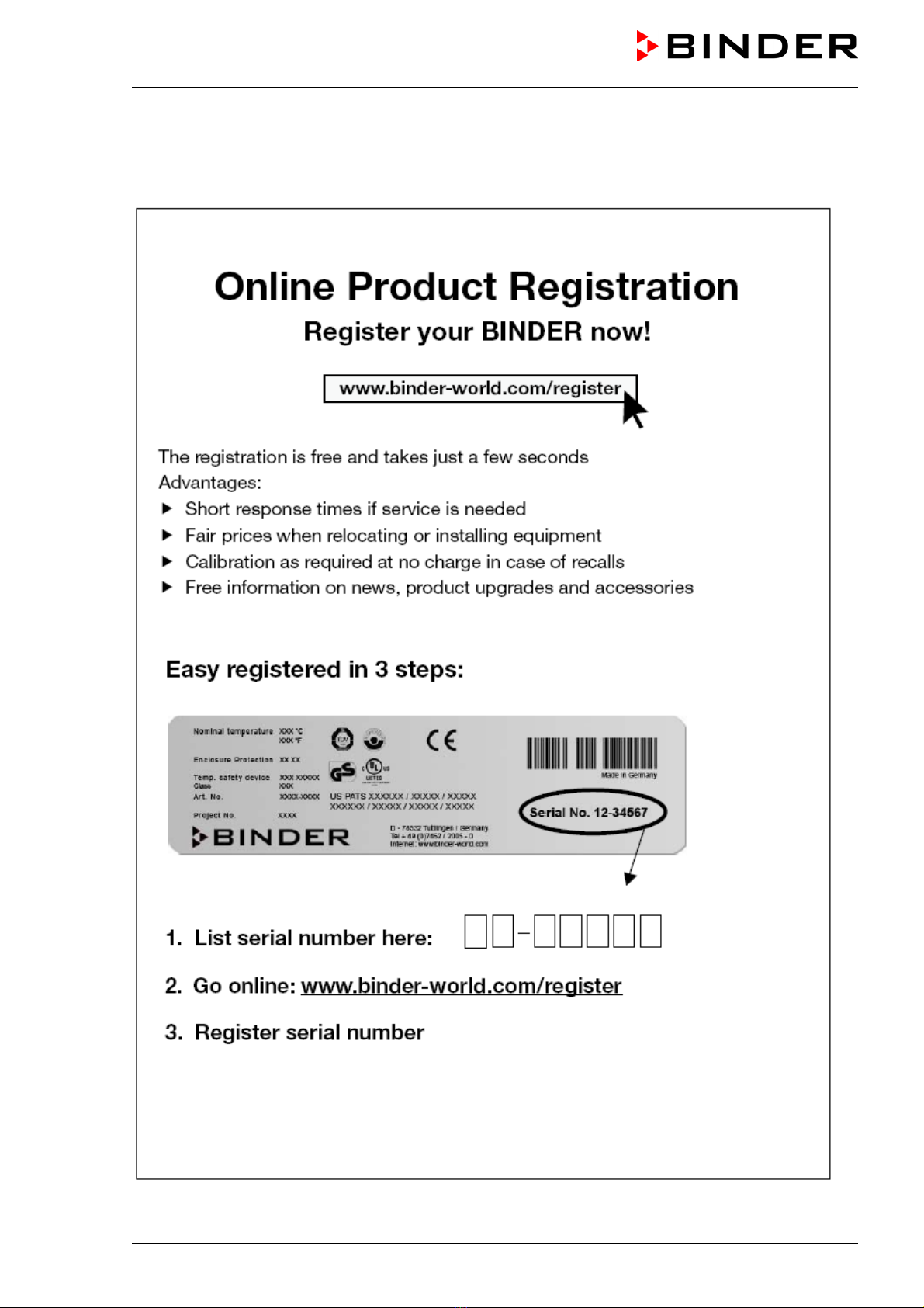
Product registration .......................................................................................................................................5
1. SAFETY..................................................................................................................8
1.1 Legal considerations ...........................................................................................................................8
1.2 Structure of the safety instructions......................................................................................................8
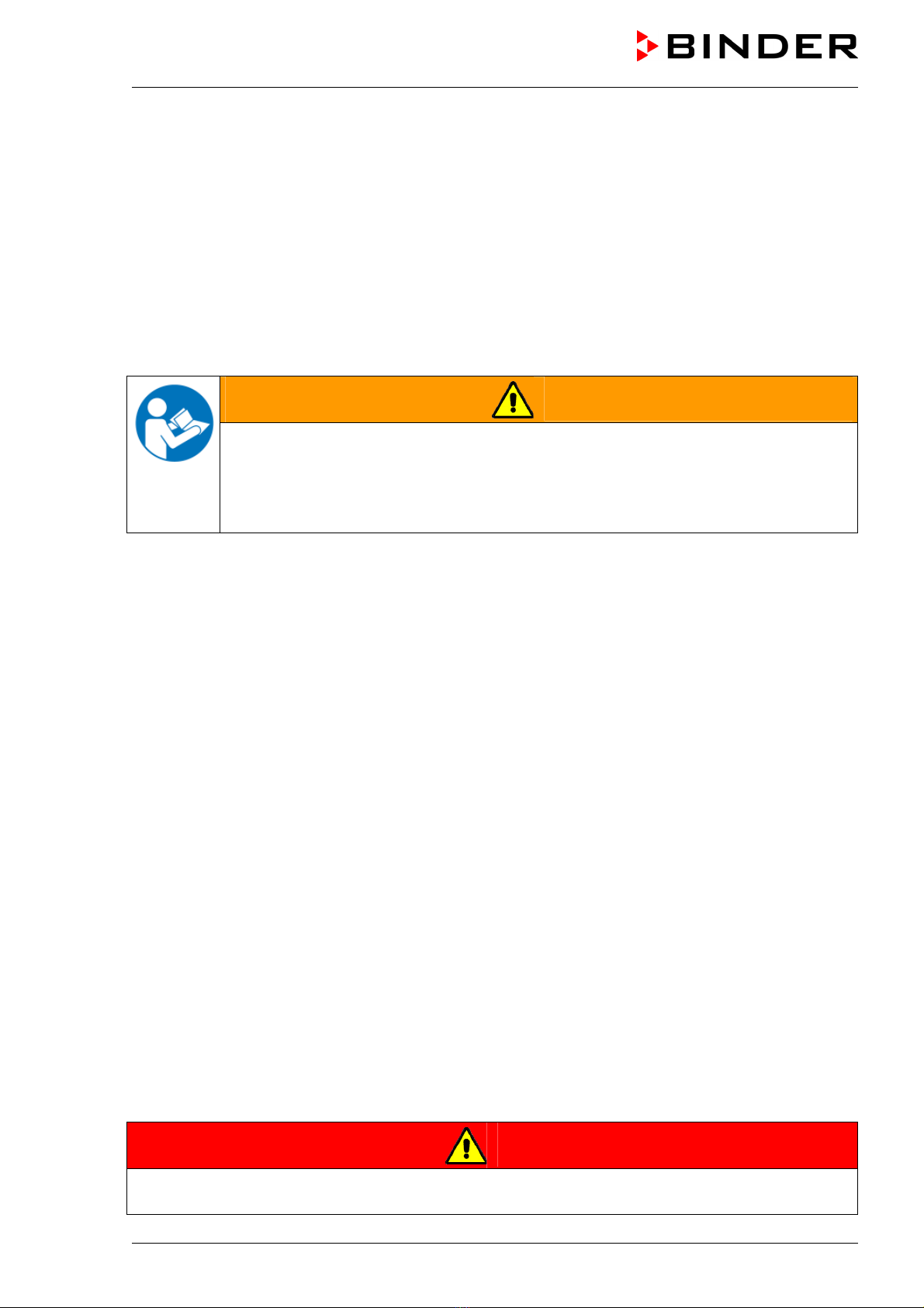
1.2.1 Signal word panel .....................................................................................................................8
1.2.2 Safety alert symbol ...................................................................................................................9
1.2.3 Pictograms................................................................................................................................9
1.2.4 Word message panel structure...............................................................................................10
1.3 Localization / position of safety labels on the unit.............................................................................10
1.4 Type plate .........................................................................................................................................11
1.5 General safety instructions on installing and operating the vacuum drying oven ............................12
1.6 Intended use .....................................................................................................................................14
2. DESCRIPTION OF THE EQUIPMENT.................................................................14
2.1 Overview of the equipment ...............................................................................................................15
2.2 VD 23 control panel...........................................................................................................................16
2.3 VD 53 / 115 control panel .................................................................................................................16
2.4 Connections at the rear of the unit....................................................................................................17
3. COMPLETENESS OF DELIVERY, TRANSPORTATION, STORAGE, AND
INSTALLATION....................................................................................................18
3.1 Unpacking, and checking equipment and completeness of delivery................................................18
3.2 Guidelines for safe lifting and transportation ....................................................................................19
3.3 Storage..............................................................................................................................................19
3.4 Location of installation and ambient conditions ................................................................................19
4. INSTALLATION AND CONNECTIONS................................................................20
4.1 Vacuum expansion racks..................................................................................................................20
4.2 Electrical connection .........................................................................................................................21
4.3 Vacuum connection ..........................................................................................................................21
4.4 Inert gas connection..........................................................................................................................22
5. START UP............................................................................................................22
5.1 Settings at the RD3 program controller ............................................................................................22
5.2 General indications ...........................................................................................................................24
6. FIXED VALUE ENTRY MODE .............................................................................25
7. WEEK PROGRAM EDITOR.................................................................................26
7.1 Program table template for Week program Editor ............................................................................28
7.2 Programming example of the Week program editor.........................................................................29
7.2.1 Desired time function ..............................................................................................................29
7.2.2 Proceeding overview ..............................................................................................................29
7.2.3 Proceeding in detail ................................................................................................................30
8. PROGRAM EDITOR.............................................................................................35
8.1 Selecting between set-point ramp and set-point step.......................................................................35
8.1.1 Programming with setting “Ramp” (default setting) ................................................................35
8.1.2 Programming with setting “step”.............................................................................................37
8.1.3 General notes on programming temperature transitions........................................................38
8.2 Set-point entry for program operation...............................................................................................38
8.3 Program table template.....................................................................................................................41
8.4 Deleting a program section ...............................................................................................................42

VD (E2.1) 10/2011 page 7/83
9. PROGRAM START LEVEL..................................................................................43
10. USER LEVEL .......................................................................................................46
11. PERFORMANCE IN CASE OF FAILURES..........................................................52
11.1 Performance after power failure........................................................................................................52
11.2 Alarm messages ...............................................................................................................................52
12. SAFETY DEVICE CLASS 2 (DIN 12880).............................................................52
13. REFERENCE MEASUREMENTS. CHECKING THE TEMPERATURE IN THE
INNER CHAMBER ...............................................................................................53
14. COMMISSIONING THE VACUUM.......................................................................54
14.1 Evacuation ........................................................................................................................................54
14.2 Breaking the vacuum (flooding) ........................................................................................................55
14.3 Operation with inert gas ....................................................................................................................55
15. SWITCHING CONTACTS 24V DC VIA OPERATION LINES ..............................55
16. OPTIONS..............................................................................................................57
16.1 Connection kit VD (option) ................................................................................................................57
16.2 Vacuum module empty (without pump) (option)...............................................................................57
16.3 Vacuum module with chemical membrane pump VP 1.1 or VP 2.1 (option)....................................59
16.4 Vacuum module with speed controlled chemical membrane pump VP 3.1 and vacuum controller
(option) ..............................................................................................................................................61
16.5 Digital pressure display (option)........................................................................................................63
16.6 Additional measuring channel for digital object temperature display with flexible Pt 100 temperature
sensor (option) ..................................................................................................................................63
16.7 Measuring access port vacuum 9 poles (option) ..............................................................................64
16.8 Communication software APT-COM™ 3 DataControlSystem (option) ............................................65
16.9 Protocol printer (available via BINDER INDIVIDUAL customized solutions)....................................65
17. MAINTENANCE, CLEANING, AND SERVICE ....................................................66
17.1 Maintenance intervals, service..........................................................................................................66
17.2 Cleaning and decontamination .........................................................................................................66
17.3 Sending the unit back to BINDER GmbH .........................................................................................67
18. DISPOSAL............................................................................................................68
18.1 Disposal of the transport packing .....................................................................................................68
18.2 Decommissioning..............................................................................................................................68
18.3 Disposal of the unit in the Federal Republic of Germany .................................................................69
18.4 Disposal of the unit in the member states of the EC except for the Federal Republic of Germany .70
18.5 Disposal of the unit in non-member states of the EC .......................................................................71
19. TROUBLESHOOTING .........................................................................................72
20. TECHNICAL DESCRIPTION................................................................................73
20.1 Factory calibration and adjustment...................................................................................................73
20.2 VD technical Data .............................................................................................................................74
20.3 Equipment and Options ....................................................................................................................75
20.4 Spare parts........................................................................................................................................77
20.5 Dimensions VD 23 ............................................................................................................................78
20.6 Dimensions VD 53 ............................................................................................................................79
20.7 Dimensions VD 115 ..........................................................................................................................80
21. CONTAMINATION CLEARANCE CERTIFICATE ...............................................81

VD (E2.1) 10/2011 page 8/83
Dear customer,
For the correct operation of the program controlled vacuum drying oven VD, it is important that you read
this operating manual completely and carefully and observe all instructions as indicated. Failure to read,
understand and follow the instructions may result in personal injury. It can also lead to damage to the unit
and/or poor equipment performance.
1. Safety
This operating manual is part of the components of delivery. Always keep it handy for reference. The
device should only be operated by laboratory personnel especially trained for this purpose and familiar
with all precautionary measures required for working in a laboratory. To avoid injuries and property
damage observe the safety instructions of the operating manual.
WARNING
Failure to observe the safety instructions.
Serious injuries and unit damage.
Observe the safety instructions in this operating manual.
Carefully read the complete operating instructions of the VD vacuum drying oven.
1.1 Legal considerations
This operating manual is for informational purposes only. It contains information for installing, start-up,
operation and maintenance of the product. Note: the contents and the product described are subject to
change without notice.
Understanding and observing the instructions in this operating manual are prerequisites for hazard-free
use and safety during operation and maintenance. In no event shall BINDER be held liable for any
damages, direct or incidental arising out of or related to the use of this manual.
This operating manual cannot cover all conceivable applications. If you would like additional information,
or if special problems arise that are not sufficiently addressed in this manual, please ask your dealer or
contact us directly by phone at the number located on page one of this manual
Furthermore, we emphasize that the contents of this operating manual are not part of an earlier or
existing agreement, description, or legal relationship, nor do they modify such a relationship. All
obligations on the part of BINDER derive from the respective purchase contract, which also contains the
entire and exclusively valid statement of warranty administration. The statements in this manual neither
augment nor restrict the contractual warranty provisions.
Have repairs performed only by experts authorized by BINDER. Repaired units must comply with the
quality standard specified by BINDER.
1.2 Structure of the safety instructions
In this operating manual, the following safety definitions and symbols indicate dangerous situations
following the harmonization of ISO 3864-2 and ANSI Z535.6.
1.2.1 Signal word panel
Depending on the probability of serious consequences, potential dangers are identified with a signal
word, the corresponding safety color, and if appropriate, the safety alert symbol.
DANGER
Indicates an imminently hazardous situation that, if not avoided, will result in death or serious
(irreversible) injury.

VD (E2.1) 10/2011 page 9/83
WARNING
Indicates a potentially hazardous situation which, if not avoided, could result in death or serious
(irreversible) injury.
CAUTION
Indicates a potentially hazardous situation which, if not avoided, may result in moderate or minor
(reversible) injury.
CAUTION
Indicates a potentially hazardous situation, which, if not avoided, may result in damage to the product
and/or its functions or to property in its proximity.
1.2.2 Safety alert symbol
Use of the safety alert symbol indicates a risk of injury.
Observe all measures that are marked with the safety alert symbol in order to avoid death or
injury.
1.2.3 Pictograms
Warning signs
Electrical hazard
Hot surface
Explosive atmosphere
Stability hazard
Inhalation hazard
Pollution Hazard
Harmful substances
Biohazard
Lifting hazard
Mandatory action signs
Mandatory regulation
Read operating
instructions
Disconnect the power
plug
Lift with several persons
Environment protection

VD (E2.1) 10/2011 page 10/83
Prohibition signs
Do NOT touch
Do NOT spray with
water
Information to be observed in order to ensure optimum function of the product.
1.2.4 Word message panel structure
Type / cause of hazard.
Possible consequences.
∅Instruction how to avoid the hazard: prohibition
Instruction how to avoid the hazard: mandatory action
Observe all other notes and information not necessarily emphasized in the same way, in order to avoid
disruptions that could result in direct or indirect injury or property damage.
1.3 Localization / position of safety labels on the unit
The following labels are located on the unit:
Pictograms (Warning signs) Service label
Hot surface
Figure 1: Position of labels on the unit
Keep safety labels complete and legible.
Replace safety labels that are no longer legible. Contact BINDER Service for these replacements.

VD (E2.1) 10/2011 page 11/83
1.4 Type plate
Figure 2: Position of type plate
Figure 3: Type plate (example of VD 23 regular unit)
Indications of the type plate Information
BINDER Manufacturer: BINDER GmbH
VD 23 Model VD 23
Serial No. 00-00000 Serial No. 00-00000
Nominal temperature 200 °C
392 °F
Nominal temperature
Enclosure protection IP 20 IP type of protection 20 acc. to EN 60529
Temp. safety device DIN 12880 Temperature safety device acc. to standard DIN 12880
Class 2.0 Temperature safety device, class 2
Art. No. 9030-0029 Art. No. 9030-0029
Project No. --- (Special application acc. to project no.)
0,80 kW Nominal power 0,80 kW
230 V 1 N ~ Nominal voltage 230 V ±10%, single-phase unit
3,5 A Nominal current 3,5 Amp
50/60 Hz Power frequency 50/60 Hz
Nominal temperature 200 °C 0,80 kW
392°F 230 V 1 N ~
Enclosure protection
Temp. safety device
IP 20
DIN 12880
3,5 A
50/60 Hz
Class 2.0
Art. No. 9030-0029 US PATS 4585923 / 5222612 / 5309981
Project No. 5405194 / 5601143 / 5773287 / 6079403
D 78532 Tuttlingen / Germany
Tel. + 49 (0) 7462/ 2005-0
Internet: www.binder-world.com
VD 23 Serial No. 00-00000
Made in Germany

VD (E2.1) 10/2011 page 12/83
Symbol on the type plate Information
CE conformity marking
Electrical and electronic equipment manufactured / placed on the
market in the EC after 13 August 2005 and to be disposed of in a
separate collection according to directive 2002/96/EC on waste
electrical and electronic equipment (WEEE).
VDE-GS certification mark
The equipment is certified in the GOST R certification system of
GOSTSTANDARD Russia.
LABORATORY EQUIPMENT
43KM
(VD-UL only)
The equipment is certified by Underwriters Laboratories Inc.®
according to standards UL 61010A-1, UL 61010A-2-10, CSA C22.2
No. 1010.1-92, and CSA C22.2 No. 1010.2.010-94.
1.5 General safety instructions on installing and operating the vacuum drying
oven
With regard to operating the vacuum drying oven VD and to the installation location, please observe the
guideline BGI/GUV-I 850-0 on safe working in laboratories (formerly BGR/GUV-R 120 or ZH 1/119
laboratory guidelines issued by the employers’ liability insurance association) (for Germany.
BINDER GmbH is only responsible for the safety features of the unit provided skilled electricians or
qualified personnel authorized by BINDER perform all maintenance and repair, and if components
relating to chamber safety are replaced in the event of failure with original spare parts.
To operate the unit, use only original BINDER accessories or accessories from third-party suppliers
authorized by BINDER. The user is responsible for any risk caused by using unauthorized accessories.
CAUTION
Danger of overheating.
Damage to the unit.
∅Do NOT install the oven in unventilated recesses.
Ensure sufficient ventilation for dispersal of the heat.
Do not operate the vacuum drying oven VD in hazardous locations.
DANGER
Explosion hazard.
Danger of death.
∅Do NOT operate the unit in potentially explosive areas.
KEEP explosive dust or air-solvent mixtures AWAY from the unit.
The vacuum drying oven VD is regularly equipped with a large-surface area safety valve. The window,
manufactured in toughened safety glass, is elastic-mounted and serves as a safety valve in the event of
explosion. The additional plastic panel provides splinter protection.

VD (E2.1) 10/2011 page 13/83
DANGER
Explosion hazard.
Danger of death.
∅Do NOT introduce any substance into the oven which is combustible or explosive at
working temperature.
∅NO explosive dust or air-solvent mixture in the inner chamber.
∅Do NOT use the vacuum drying oven for drying or heat treatments leading to release of
combustible vapors able to form an explosive mixture with air.
Any solvent contained in the charging material must not be explosive or inflammable. I.e., irrespective of
the solvent concentration in the steam room, NO explosive mixture with air must form. The drying
temperature must lie below the flash point or below the sublimation point of the charging material.
Familiarize yourself with the physical and chemical properties of the charging material, as well as the
contained moisture constituent and its behavior with the addition of heat energy and changes in pressure.
Familiarize yourself with any potential health risks caused by the charging material, the contained
moisture constituent or by reaction products that may arise during the drying process. Take adequate
measures to exclude such risks prior to putting the vacuum drying oven into operation.
DANGER
Electrical hazard.
Danger of death.
∅The oven must NOT become wet during operation or maintenance.
The vacuum drying ovens were produced in accordance with the relevant VDE regulations and were
routinely tested in accordance to VDE 0411-1 (IEC 61010-1).
CAUTION
The inner chamber will become hot during operation.
Danger of burning.
∅Do NOT touch the inner surfaces or the charging material during operation.
In the case of operation with inert gas, the unit is supplied with an oxygen-displacing gas (e.g. N2). The
gas emerging from the system must therefore be removed from the installation area by means of a
suitable extraction system (see technical ventilation measures in the guideline BGI/GUV-I 850-0 on safe
working in laboratories (formerly BGR/GUV-R 120 or ZH 1/119 laboratory guidelines issued by the
employers’ liability insurance association) (for Germany).
With use of a vacuum system or a vacuum pump, observe the permitted gas inlet
temperature. Observe the safety instructions of the pump manufacturer.

VD (E2.1) 10/2011 page 14/83
1.6 Intended use
The VD vacuum drying ovens are suitable for drying and heat treatment of solid or pulverized charging
material, as well as bulk material, using the supply of heat under vacuum. The solvent content must not
be explosive or flammable. A mixture of any component of the charging material with air must NOT be
explosive. The drying temperature must lie below the flash point or below the sublimation point of the
charging material.
Observing the instructions in this operating manual and conducting regular maintenance
work (chap. 17) is part of the intended use.
2. Description of the equipment
Vacuum drying is used for special drying problems, for which conventional drying methods cannot offer a
solution due to physical limitations.
All functions of the multifunctional program control can be set simply and conveniently via the easy to
understand function keypad of the RD3 temperature program controller. This controller is equipped with
touch function keys and a digital display and permits exact temperature setting and programming
temperature cycles. The VD provides almost unlimited possibilities of adapting to individual customer
requirements based upon extensive programming options and on the week program timer and real time
clock of the controller.
The electro-polished inner chamber, the rack holder, and all of the unit's vacuum connections and valves
are made of especially corrosion resistant stainless steel V4A (material no. 1.4571 in Germany). The
housing is RAL 7035 powder-coated. All corners and edges are also completely coated. When operating
the chamber at temperatures above 150 °C / 302°F, the impact of the oxygen in the air may cause
discoloration of the metallic surfaces (yellowish-brown or blue) by natural oxidation processes. These
colorations are harmless and will in no way impair the function or quality of the unit.
The vacuum drying ovens in the APT.line™ are jacket-heated. The APT.line™ preheating chamber
technique ensures a completely homogeneous jacket temperature, ensuring uniform heat transfer into
the inner chamber. The low-loss heat transfer to the material uses the patented aluminum vacuum
expansion racks (or optionally available in stainless steel). The elastic-mounted safety glass window
reliably compensates any overpressure or explosions that may occur. The additional polycarbonate panel
ensures proven and effective splinter protection in the event of an implosion.
All VD units provide an inert gas connection and a measuring connection serving to connect a vacuum
controller or a measuring access port.
The VD vacuum drying ovens are equipped as standard with a large-surface safety valve. The toughened
safety glass window is elastic-mounted and in the event of explosion serves as a safety valve. The
additional plastic panel provides splinter protection.
The VD vacuum drying oven is equipped with a serial interface RS 422 for computer communication, e.g.
via the communication software APT-COM™ 3 DataControlSystem (option, chap.16.8). For further
options, see chap. 20.3.
All installable items, such as racks and rack holders, can be easily removed. The completely smooth
inner chamber with its rounded corners and internally welded seams is easy to clean.
The minimum working temperature of the vacuum drying oven is approx. 15 °C / 27 °F above room
temperature. The maximum temperature is 200 °C / 392°F.
Vacuum pumps with a suction capacity of 1 m3/h to 30 m3/h are suitable for the VD vacuum drying oven.
The permissible end vacuum is 10-2 mbar / 0.0003 inHg.

VD (E2.1) 10/2011 page 15/83
2.1 Overview of the equipment
Figure 4: VD 23 with option vacuum module and chemical membrane pump
(A) Control panel
(B) Unit door
(C) Elastic-mounted safety glass window
(D) Vacuum module (option)
(E) Chemical membrane pump (option)
(A)
(B)
(C)
(D)
(E)

VD (E2.1) 10/2011 page 16/83
2.2 VD 23 control panel
(7) (8) (4) (3) (2) (2a) (1)
Figure 5: VD 23 control panel
(1) On/off switch (main power switch)
(2) Temperature safety device class 2
(2a) Red alarm lamp of the safety device class 2
(3) Manometer (pressure reading)
(4) Aeration valve (inert gas or ambient air)
(7) Program controller RD3
(8) Vacuum shut-off valve
2.3 VD 53 / 115 control panel
(8) (7) (6) (5) (3) (2) (2a) (1)
Figure 6: VD 53/115 control panel
(1) On/off switch (main power switch)
(2) Temperature safety device class 2
(2a) Red alarm lamp of the safety device class 2
(3) Manometer (pressure reading)
(5) Aeration valve (ambient air)
(6) Fine dosing valve (inert gas)
(7) Program controller RD3
(8) Vacuum shut-off valve
VAC.OFF
VAC.ON
AIR
GAS
AIR/GAS
VAC.OFF
VAC.ON

VD (E2.1) 10/2011 page 17/83
2.4 Connections at the rear of the unit
(10) (11) (12) (13) (14) (15) (16) (9)
Figure 7: Rear of VD
(9) RS 422 serial interface for computer communication
(10) Miniature fuse
(11) Power connection line
(12) Inert gas connection, adapter with hose olive ∅8 mm / 0.31 in
(VD23: also simultaneous fresh air connection)
(13) Vacuum connection with small flange DN16
(14) DIN socket (option) for option “object temperature display”
(15) DIN socket (operation line 2) (option) for option “program controlled venting”
(16) DIN socket (operation line 1) (option) for option “vacuum module with pump”
(17) Measuring connection with small flange DN16
(17)

VD (E2.1) 10/2011 page 18/83
3. Completeness of delivery, transportation, storage, and
installation
3.1 Unpacking, and checking equipment and completeness of delivery
After unpacking, please check the unit and its optional accessories, if any, based on the delivery receipt
for completeness and for transportation damage. Inform the carrier immediately if transportation damage
has occurred.
The final tests of the manufacturer may have caused traces of the shelves on the inner surfaces. This has
no impact on the function and performance of the unit.
Please remove any transportation protection devices and adhesives in/on the unit and on the doors and
remove the operating manuals and accessory equipment.
CAUTION
Sliding or tilting of the unit.
Damage to the unit.
Risk of injury by lifting heavy loads.
∅Do NOT lift or transport the unit using the door handle, the door or the lower housing.
Lift units size 23 and 53 from the pallet at the four lower corners with the aid of 4
people.
Lift units size 115 from the pallet with the aid of 6 people.
If you need to return the unit, please use the original packing and observe the guidelines for safe lifting
and transportation (chap. 3.2).
For disposal of the transport packing, see chap. 18.1.
If you ordered the option “vacuum module with chemical membrane pump”, the pump will be delivered in
a separate box and must be fitted into the module and connected at the place of installation (see chap.
16.3 and 16.4).
Note on second-hand units (Ex-Demo-Units):
Second-hand units are units that were used for a short time for tests or exhibitions. They are thoroughly
tested before resale. BINDER ensures that the chamber is technically sound and will work flawlessly.
Second-hand units are marked with a sticker on the unit door. Please remove the sticker before
commissioning the unit.

VD (E2.1) 10/2011 page 19/83
3.2 Guidelines for safe lifting and transportation
After operation, please observe the guidelines for temporarily decommissioning the unit (chap. 18.2).
CAUTION
Sliding or tilting of the unit.
Damage to the unit.
Risk of injury by lifting heavy loads.
Transport the unit in its original packaging only.
For moving or shipping, secure the oven with transport straps.
∅Do NOT lift or transport the unit using the door, the handle, or the lower housing.
Lift units size 23 and 53 at the four lower corners with the aid of 4 people.
Lift units size 115 with the aid of 6 people.
•Permissible ambient temperature range during transport: -10 °C / 14°F to +60 °C / 140°F.
You can order transport packing for moving or shipping purposes from BINDER Service.
3.3 Storage
Intermediate storage of the unit in a closed and dry room. Observe the guidelines for temporary
decommissioning (chap. 18.2).
•Permissible ambient temperature range during storage: -10 °C / 14°F to +60 °C / 140°F.
•Permissible ambient humidity: max. 70 % r.H., non-condensing
When after storage in a cold location you transfer the unit to its warmer installation site, condensation
may form. Before start-up, wait at least one hour until the chamber has attained ambient temperature and
is completely dry.
3.4 Location of installation and ambient conditions
Set up the VD vacuum drying oven on a flat, even, and non-flammable surface, free from vibration, in a
well-ventilated, dry location. Align it using a spirit level. The site of installation must be capable of
supporting the unit’s weight (see technical data, chap. 20.2). The chambers are designed for setting up
inside a building (indoor use).
CAUTION
Danger of overheating.
Damage to the unit.
∅Do NOT set up units in non-ventilated recesses.
Ensure sufficient ventilation for dispersal of the heat.
•Permissible ambient temperature range during operation: +18 °C / 64°F to +32 °C / 90°F.
The ambient temperature should not be substantially higher than the indicated ambient
temperature of +25 °C / 77°F to which the specified technical data relate. Deviations from the
indicated data are possible for other ambient conditions.
•Permissible ambient humidity: 70 % r.H. max., non-condensing.
•Installation height: max. 2000 m / 6562 ft above sea level.

VD (E2.1) 10/2011 page 20/83
When placing several units of the same size side by side, maintain a minimum distance of 250 mm / 9.8
in between each unit. Wall distances: rear 100 mm / 3.9 in, sides 135 mm / 5.3 in. Spacing above and
behind the unit of at least 100 mm / 3.9 in must also be maintained.
CAUTION
Danger by stacking.
Damage to the units.
∅Do NOT place vacuum drying ovens on top of each other.
To completely separate the unit from the power supply, you must disconnect the power plug. Install the
unit in a way that the power plug is easily accessible and can be easily pulled in case of danger.
Do not install or operate the vacuum drying oven VD in potentially explosive areas.
DANGER
Explosion hazard.
Danger of death.
∅Do NOT operate the unit in potentially explosive areas.
KEEP explosive dust or air-solvent mixtures AWAY from the vicinity of the unit.
For operation with inert gas, the unit is supplied with an oxygen-displacing gas, e.g. N2. The gas
emerging from the system must be removed from the installation area by means of a suitable extraction
system (see technical ventilation measures in the guideline BGI/GUV-I 850-0 on safe working in
laboratories (formerly BGR/GUV-R 120 or ZH 1/119 laboratory guidelines issued by the employers’
liability insurance association) (for Germany).
The maximum permissible ambient temperature of the vacuum pumps delivered by BINDER is 40 °C /
104°F.
4. Installation and connections
4.1 Vacuum expansion racks
The low-loss heat transfer to the material occurs via the
patented aluminum vacuum expansion racks (also available in
stainless steel as an option). The strong tension causes the
racks to fit tightly against the interior wall and their large-
surface contact area ensures rapid and effective heat transfer.
The removable rack holders allow for easy positioning.
You can also remove the expansion racks for easy cleaning.
Do not remove them too often in order to prevent wear.
Figure 8: Using the expansion racks
•Pushing the locking lever: The expansion rack is released and can be removed.
•Pulling the locking lever: The expansion rack is pressed against the inner chamber walls.
Following each new tightening of an expansion rack, check that the lateral parts of the rack fit
closely over their whole surface to the inner chamber wall. This is necessary in order to
ensure the specified temperature exactitude.
This manual suits for next models
18
Table of contents
Other Binder Oven manuals

Binder
Binder APT.line FED User manual

Binder
Binder M Series User manual

Binder
Binder VDL Series User manual

Binder
Binder FDL 115 User manual

Binder
Binder FED 53 User manual

Binder
Binder VD Series User manual

Binder
Binder FED Series User manual

Binder
Binder VDL Series User manual

Binder
Binder VDL Series User manual

Binder
Binder FDL 115 User manual
Popular Oven manuals by other brands

Franke
Franke FRE60M5B user manual

AEG
AEG BES355010M user manual

Cuppone
Cuppone Donatello LLKDN435 PRE-INSTALLATION AND INSTALLATION MANUAL

montpellier
montpellier MON-SFO59LED Installation and operating instructions

Electrolux
Electrolux EOB6630 operating instructions

Electrolux
Electrolux KCF4P61TX user manual