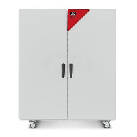
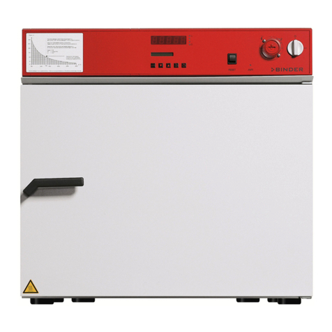
Binder FDL 115 User manual

Issue 05/2016 Art. No. 7001-0261
Operating Manual
Translation of the Original Operating Manual
FDL 115
Safety drying ovens
for drying of limited quantities of solvents
with microprocessor program controller RD3
Model
Model version
Art. No.
FDL 115 (E2.1)
FDL115-230V
9010-0292, 9110-0292
BINDER GmbH
Address Post office box 102
D-78502 Tuttlingen
Tel. +49 7462 2005 0
Fax +49 7462 2005 100
Internet http://www.binder-world.com
E-mail info@binder-world.com
Service Hotline +49 7462 2005 555
Service Fax +49 7462 2005 93 555
Service E-Mail service@binder-world.com
Service Hotline USA +1 866 885 9794 or +1 631 224 4340 x3
Service Hotline Asia Pacific +852 390 705 04 or +852 390 705 03
Service Hotline Russia and CIS +7 495 988 15 16

FDL (E2.1) 05/2016 page 2/75
Contents
1. SAFETY.................................................................................................................. 4
1.1 Legal considerations ...........................................................................................................................4
1.2 Structure of the safety instructions......................................................................................................4
1.2.1 Signal word panel......................................................................................................................4
1.2.2 Safety alert symbol....................................................................................................................5
1.2.3 Pictograms.................................................................................................................................5
1.2.4 Word message panel structure .................................................................................................6
1.3 Localization / position of safety labels on the chamber ......................................................................6
1.4 Type plate ...........................................................................................................................................7
1.5 General safety instructions on installing and operating the chambers ...............................................8
1.6 Intended use .......................................................................................................................................9
1.7 Operating instructions .........................................................................................................................9
1.8 Measures to prevent accidents.........................................................................................................10
1.9 Important points to consider before commissioning .........................................................................12
1.9.1 Technical ventilation / permissible load...................................................................................12
1.9.2 Loading instructions ................................................................................................................12
1.9.3 Drying nitro-cellulose lacquers ................................................................................................12
1.9.4 Drying mould varnishes...........................................................................................................12
1.9.5 Drying impregnating resins......................................................................................................12
2. CHAMBER DESCRIPTION .................................................................................. 13
2.1 Chamber overview ............................................................................................................................14
2.2 Control panel.....................................................................................................................................15
2.3 Solvent curve FDL 115 .....................................................................................................................15
3. COMPLETENESS OF DELIVERY, TRANSPORTATION, STORAGE, AND
INSTALLATION.................................................................................................... 16
3.1 Unpacking, and checking equipment and completeness of delivery................................................16
3.2 Guidelines for safe lifting and transportation ....................................................................................17
3.3 Storage..............................................................................................................................................17
3.4 Location of installation and ambient conditions ................................................................................17
4. INSTALLATION OF THE EQUIPMENT ............................................................... 18
4.1 Operating instructions .......................................................................................................................18
4.2 Electrical connection .........................................................................................................................19
4.3 Connection to a suction plant (optional) ...........................................................................................19
5. START UP............................................................................................................ 20
5.1 Settings at the RD3 program controller ............................................................................................20
5.2 General indications ...........................................................................................................................22
6. FIXED VALUE ENTRY MODE ............................................................................. 23
7. WEEK PROGRAM EDITOR................................................................................. 24
7.1 Program table template for Week program Editor ............................................................................26
8. PROGRAM EDITOR............................................................................................. 27
8.1 Selecting between set-point ramp and set-point step.......................................................................27
8.1.1 Programming with setting “Ramp” (default setting).................................................................27
8.1.2 Programming with setting “step” .............................................................................................29
8.1.3 General notes on programming temperature transitions ........................................................30
8.2 Set-point entry for program operation...............................................................................................30
8.3 Program table template.....................................................................................................................33
8.4 Deleting a program section...............................................................................................................34

FDL (E2.1) 05/2016 page 3/75
9. PROGRAM START LEVEL.................................................................................. 35
10. USER LEVEL ....................................................................................................... 37
11. BEHAVIOR IN CASE OF FAILURES................................................................... 44
11.1 Behavior after a power failure ...........................................................................................................44
11.2 Alarm messages ...............................................................................................................................44
12. SAFETY DEVICES ............................................................................................... 44
12.1 Temperature safety device class 2 ...................................................................................................44
12.2 Exhaust air monitoring ......................................................................................................................46
13. OPTIONS.............................................................................................................. 47
13.1 Communication software APT-COM™ 3 DataControlSystem (option) ............................................47
13.2 Ethernet interface (available via BINDER INDIVIDUAL customized solutions)................................47
13.3 Coil-coating door flap (option)...........................................................................................................47
13.4 Additional measuring channel for digital object temperature indicator with pincer-type sensor
(option) ..............................................................................................................................................48
14. MAINTENANCE, CLEANING, AND SERVICE .................................................... 49
14.1 Maintenance intervals, service..........................................................................................................49
14.2 Cleaning and replacing the intake filter.............................................................................................50
14.3 Cleaning and decontaminating the safety drying oven.....................................................................50
14.4 Cleaning ............................................................................................................................................50
14.5 Decontamination ...............................................................................................................................52
14.6 Sending the chamber back to BINDER GmbH.................................................................................53
15. DISPOSAL............................................................................................................ 53
15.1 Disposal of the transport packing .....................................................................................................53
15.2 Decommissioning..............................................................................................................................54
15.3 Disposal of the chamber in the Federal Republic of Germany.........................................................54
15.4 Disposal of the chamber in the member states of the EC except for the Federal Republic of
Germany ...........................................................................................................................................55
15.5 Disposal of the chamber in non-member states of the EC ...............................................................56
16. TROUBLESHOOTING ......................................................................................... 57
17. TECHNICAL DESCRIPTION................................................................................ 59
17.1 Factory calibration and adjustment...................................................................................................59
17.2 Definition of usable volume...............................................................................................................59
17.3 Technical data FDL 115....................................................................................................................59
17.4 Equipment and Options (extract) ......................................................................................................62
17.5 Accessories and spare parts (extract) ..............................................................................................63
17.6 Dimensions FDL 115 ........................................................................................................................64
18. CERTIFICATES AND DECLARATIONS OF CONFORMITY............................... 65
18.1 EU Declaration of Conformity ...........................................................................................................65
18.2 Certificate for the GS mark of conformity of the “Deutsche Gesetzliche Unfallversicherung e.V.”
(German Social Accident Insurance (DGUV) ...................................................................................67
19. PRODUCT REGISTRATION ................................................................................ 69
20. CONTAMINATION CLEARANCE CERTIFICATE ............................................... 70
20.1 For chambers located outside USA and Canada .............................................................................70
20.2 For chambers in USA and Canada...................................................................................................73

FDL (E2.1) 05/2016 page 4/75
Dear customer,
For the correct operation of the safety drying ovens FDL, it is important that you read this operating man-
ual completely and carefully and observe all instructions as indicated. Failure to read, understand and
follow the instructions may result in personal injury. It can also lead to damage to the chamber and/or
poor equipment performance.
1. Safety
This operating manual is part of the components of delivery. Always keep it handy for reference. The
device should only be operated by laboratory personnel especially trained for this purpose and familiar
with all precautionary measures required for working in a laboratory. Observe the national regulations on
minimum age of laboratory personnel. To avoid injuries and damage observe the safety instructions of
the operating manual.
WARNING
Failure to observe the safety instructions.
Serious injuries and chamber damage.
Observe the safety instructions in this operating manual.
Carefully read the complete operating instructions of the safety drying oven FDL.
1.1 Legal considerations
This operating manual is for informational purposes only. It contains information for installing, start-up,
operation and maintenance of the product. Note: the contents and the product described are subject to
change without notice.
Understanding and observing the instructions in this operating manual are prerequisites for hazard-free
use and safety during operation and maintenance. In no event shall BINDER be held liable for any dam-
ages, direct or incidental arising out of or related to the use of this manual.
This operating manual cannot cover all conceivable applications. If you would like additional information,
or if special problems arise that are not sufficiently addressed in this manual, please ask your dealer or
contact us directly by phone at the number located on page one of this manual
Furthermore, we emphasize that the contents of this operating manual are not part of an earlier or exist-
ing agreement, description, or legal relationship, nor do they modify such a relationship. All obligations on
the part of BINDER derive from the respective purchase contract, which also contains the entire and ex-
clusively valid statement of warranty administration. The statements in this manual neither augment nor
restrict the contractual warranty provisions.
1.2 Structure of the safety instructions
In this operating manual, the following safety definitions and symbols indicate dangerous situations in
accordance with ISO 3864-2 and ANSI Z535.6.
1.2.1 Signal word panel
Depending on the probability of serious consequences, potential dangers are identified with a signal
word, the corresponding safety color, and if appropriate, the safety alert symbol.
DANGER
Indicates an imminently hazardous situation that, if not avoided, will result in death or serious (irreversi-
ble) injury.

FDL (E2.1) 05/2016 page 5/75
WARNING
Indicates a potentially hazardous situation which, if not avoided, could result in death or serious (irre-
versible) injury.
CAUTION
Indicates a potentially hazardous situation which, if not avoided, may result in moderate or minor (re-
versible) injury.
CAUTION
Indicates a potentially hazardous situation which, if not avoided, may result in damage to the product
and/or its functions or of a property in its proximity.
1.2.2 Safety alert symbol
Use of the safety alert symbol indicates a risk of injury.
Observe all measures that are marked with the safety alert symbol in order to avoid death or
injury.
1.2.3 Pictograms
Warning signs
Electrical hazard
Hot surface
Explosive atmosphere
Tipover hazard
Inhalation hazard
Risk of corrosion and /
or chemical burns
Harmful substances
Biohazard
Pollution Hazard
Mandatory action signs
Mandatory regulation
Read operating
instructions
Disconnect the power
plug
Lift with several persons
Environment protection
Wear protective gloves
Wear safety goggles

FDL (E2.1) 05/2016 page 6/75
Prohibition signs
Do NOT touch
Do NOT spray with
water
Information to be observed in order to ensure optimum function of the product.
1.2.4 Word message panel structure
Type / cause of hazard.
Possible consequences.
∅Instruction how to avoid the hazard: prohibition
Instruction how to avoid the hazard: mandatory action
Observe all other notes and information not necessarily emphasized in the same way, in order to avoid
disruptions that could result in direct or indirect injury or property damage.
1.3 Localization / position of safety labels on the chamber
The following labels are located on the chamber:
Pictograms (Warning signs)
Service label
Hot surface
Figure 1: Position of labels on the chamber
Keep safety labels complete and legible.
Replace safety labels that are no longer legible. Contact BINDER Service for these replacements.

FDL (E2.1) 05/2016 page 7/75
1.4 Type plate
The type plate sticks to the left side of the chamber, bottom right-hand.
Figure 2: Type plate (example of FDL 115 regular chamber)
Indications of the type plate
Information
BINDER
Manufacturer: BINDER GmbH
FDL 115
Model
Safety Drying Oven
Chamber name
Serial No.
00-00000
Serial no. of the chamber
Built
2016
Year of construction
Nominal temperature 300 °C
572 °F
Nominal temperature
IP protection
33
Type of IP protection acc. to standard EN 60529
Temp. safety device
DIN 12880
Temperature safety device acc. to standard DIN 12880:2007
Class
2.0
Class of temperature safety device
Art. No.
9010-0292
Art. no. of the chamber
Project No.
---
Optional: Special application acc. to project no.
2,90 kW
Nominal power
230 V 1 N PE ~
Nominal voltage 230 V
±
5%, single-phase unit
13,0 A
Nominal current
230 V / 50 Hz
Nominal voltage +/- 5%
at the indicated power frequency
230 V / 60 Hz
1 N ~
Current type
Usable volume 0,115m³
Usable volume
Steam space 0,156m³
Total steam space 0
Max. solvent at nominal temp. 3,0g
Highest permissible solvent quantity at 300 °C / 572°F
Min. exhaust flow rate 24m³/h at +20 °C
Minimum exhaust flow rate at +20 °C
Max. temp. of heating surfaces +750 °C
Maximum temperature of heating surfaces +750 °C / 1382°F
Wiring diagram 55535004
Wiring diagram of FDL 115
Symbol on the type plate
Information
CE conformity marking
Electrical and electronic equipment manufactured / placed on the
market in the EC after 13 August 2005 and to be disposed of in a
separate collection according to directive 2002/96/EC on waste
electrical and electronic equipment (WEEE).
Nominal temp.
300 °C
1,90 kW / 13,0 A
Usable volume 0,115m³
572 °F
230 V / 50 Hz
Steam space 0,156m³
IP protection
33
230 V / 60 Hz
Max. solvent at nominal temp. 3,0g
Safety device
DIN 12880
1 N PE ~
Min. exhaust flow rate 24m³/h at +20 °C
Class
2.0
Max. temp. of heating surfaces +750 °C
Art. No.
9010-0292
Wiring diagram 55535004
Project No.
Built
2016
Safety Drying Oven
BINDER GmbH
Im Mittleren Ösch 5
78532 Tuttlingen / Germany
www.binder-world.com
FDL 115
E2.1
Serial No. 00-00000
Made in Germany

FDL (E2.1) 05/2016 page 8/75
Symbol on the type plate
Information
The equipment is certified according to Customs Union Technical
Regulation (CU TR) for Russia, Belarus and Kazakhstan
GS mark of conformity of the “Deutsche Gesetzliche Unfallversi-
cherung e.V. (DGUV), Fachausschuss Metall- und Oberflächen-
behandlung, Prüf- und Zertifizierungsstelle im DGUV Test“ (Ger-
man Social Accident Insurance (DGUV), Expert Committee: Metal
and Surface Treatment, Testing and Certification Body in DGUV)
1.5 General safety instructions on installing and operating the chambers
With regard to operating the chambers and to the installation location, please observe the DGUV guide-
lines 213-850 on safe working in laboratories (formerly BGI/GUV-I 850-0, BGR/GUV-R 120 or ZH 1/119,
issued by the employers’ liability insurance association) (for Germany).
BINDER GmbH is only responsible for the safety features of the chamber provided skilled electricians or
qualified personnel authorized by BINDER perform all maintenance and repair, and if components relat-
ing to chamber safety are replaced in the event of failure with original spare parts.
To operate the chamber, use only original BINDER accessories or accessories from third-party suppliers
authorized by BINDER. The user is responsible for any risk caused by using unauthorized accessories.
CAUTION
Danger of overheating.
Damage to the chamber.
∅Do NOT install the chamber in unventilated recesses.
Ensure sufficient ventilation for dispersal of the heat.
Do not operate the chamber in hazardous locations.
DANGER
Explosion hazard.
Danger of death.
∅Do NOT operate the chamber in potentially explosive areas.
∅KEEP explosive dust or air-solvent mixtures AWAY from the chamber.
Familiarize yourself with any potential health risks caused by the charging material, the contained mois-
ture constituent or by reaction products which may arise during the temperature process. Take adequate
measures to exclude such risks prior to putting the safety drying oven into operation.
DANGER
Electrical hazard.
Danger of death.
∅The chamber must NOT become wet during operation or maintenance.
The chambers were produced in accordance with VDE regulations and were routinely tested in accord-
ance to VDE 0411-1 (IEC 61010-1).

FDL (E2.1) 05/2016 page 9/75
If a warning signal indicates an error condition, no further charging material must be introduced into the
chamber.
DANGER
Explosion and ignition hazard.
Danger of death.
∅Do NOT introduce any further charging material as long as there is a warning signal.
During and after the drying process, the inner surfaces have got a temperature close to the set-point.
CAUTION
The inner chamber, the exhaust duct, the door gasket, and the access ports will be-
come hot during operation.
Danger of burning.
∅Do NOT touch the inner surfaces, the exhaust duct, the door gasket, the access ports,
or the charging material during operation.
1.6 Intended use
The BINDER safety drying oven FDL 115 is suitable for drying and burn in of lacquers and similar liquid
coating materials which are containing solvents that can form explosive mixtures with air. The maximally
permitted drying temperature and the maximally permitted quantity of solvent are limited, see chap. 1.9.
The chamber is also suited for coil coating / hot air short cycle applications.
Other applications are not approved.
Do NOT use the chamber to warm up coating materials in containers, vessels, etc. or for drying textiles
soaked in solvent.
Do NOT use the chamber for drying purpose if greater quantities of steam or solvent gas leading to con-
densation will be set free.
Following the instructions in this operating manual and conducting regular maintenance work
(chap. 14.1) are part of the intended use.
The charging material shall not contain any corrosive ingredients that may damage the ma-
chine components made of stainless steel, aluminum, and copper. Such ingredients include in
particular acids and halides. Any corrosive damage caused by such ingredients is excluded
from liability by BINDER GmbH.
1.7 Operating instructions
Depending on the application and location of the chamber, the operator of the safety drying oven must
provide the relevant information for safe operation of the chamber in a set of operating instructions.
These operating instructions must be kept with the chamber at all times in a place where they
are clearly visible. They must be comprehensible and written in the language of the employ-
ees.

FDL (E2.1) 05/2016 page 10/75
1.8 Measures to prevent accidents
During drying of fluid paints, flammable solvent/air mixtures can form and ignite.
The manufacturer took the following measures to prevent ignition and explosions:
•Indications on the type plate
See operating manual chap. 1.4
•Operating manual
An operating manual is available for each safety drying oven.
A diagram in the operating manual (chap. 2.3) indicates the maximum permissible solvent quantities
for various operating states.
The operating manual asks the operator of the safety drying oven to set up an instruction on the per-
missible loading quantity.
•Maximum temperatures and maximum permissible steam concentration
By means of the diagram “Highest permissible solvent quantity”, which is included in the operating
manual chap. 2.3 and applied on the front of the safety drying oven, the operator must adapt the dry-
ing temperature to the maximum solvent quantity arising.
When using nitro-cellulose lacquers or nitro combination lacquers, the diagram ”Highest permissible
solvent quantity” specifies a limit temperature of max. 130 °C/ 266 °F, which must not be exceeded.
(In this context, all paints containing more than 5 % nitro-cellulose relative to the non-volatile contents
are regarded as nitro-cellulose lacquers and nitro-combination lacquers).
A gas-tight separation between the drying chamber and the heating chamber is not necessary since
there is an effective forced air motion in the entire steam room.
•Throttle valves
No throttle valves are used, i.e., the full air change occurs permanently.
•Protecting the heating surfaces against dripping
All heating elements are protected against lacquer dripping and direct contact with lacquer coatings.
•Heat insulation
All heat insulation is sealed against penetration by lacquer vapors from the outside with high tempera-
ture-resistant and ageing-resistant sealant.
The insulation material consists of non-combustible mineral wool (class A1 according to DIN 4102-
1:1998).
•Overtemperature monitoring
The safety drying oven is equipped with a temperature display, which can be read from outside.
A built-in additional temperature safety device can turn off the heating and is functionally independent
of the main controller. When turning off the chamber, the forced convection and the control equip-
ment’s function are maintained.
Visual (red indicator light) and audible (buzzer) signals indicate temperature exceeding.
•Monitoring the stream of exhaust air during prepurge
The chamber complies with the requirements on monitoring the pressure switch according to EN
1539:2015 and EN ISO 13849:2008.
The fan only turns on after pressing pushbutton “START” (4).
After approx. 2 minutes of prepurge with monitoring the stream of exhaust air the heating turns on.
•Door switch
If the door is opened briefly (less than 2 minutes) the heating turns off. When opening the door for
longer than 2 minutes, fan and heating turn off. To restart the drying process in this case, new pre-
purge is required.

FDL (E2.1) 05/2016 page 11/75
•Safety in case the technical ventilation fails
The heating only turns on if the air circulation is already in operation.
If the air circulation fails, the heating immediately turns off. In addition, there is a visual signal: red in-
dicator light “AIR” (3). As an additional indication there is an acoustical signal which can be reset on
the controller.
•Moving parts participating in the work process
It is impossible to touch the fan from outside the device or from the interior.
•Safety, measurement and control devices
The safety, measuring, and control equipment is easily accessible via the housing top cover.
•Electrostatic charge
The interior parts are grounded.
•Protection against touchable surfaces
Tested according to EN ISO 13732-1:2008.
•Floors
See operating manual chap. 3.4 for the oven’s installation.
•Ventilation
Ventilation shall be realized by the operator according to GUV-R 500 chap. 2.29 “Verarbeiten von
Beschichtungsstoffen” (Processing of paints) (for Germany).
•Cleaning
See operating manual chap. 14.
•Examinations
The safety drying oven has been inspected by the “Deutsche Gesetzliche Unfallversicherung e.V.
(DGUV), Fachausschuss Nahrungs- und Genussmittel, Prüf- und Zertifizierungsstelle im DGUV Test“
(German Social Accident Insurance (DGUV), Expert Committee: “Metal and Surface Treatment”, Test-
ing and Certification Body in DGUV) and bears the GS mark.

FDL (E2.1) 05/2016 page 12/75
1.9 Important points to consider before commissioning
1.9.1 Technical ventilation / permissible load
For safety reasons, the formation of a dangerous, explosive atmosphere must be avoided in all operating
modes (see GUV-R 500 chap. 2.28 “Betreiben von Trocknern für Beschichtungsstoffe” ("Dryers for coat-
ing materials")). Keeping the maximum permissible amount of solvent when loading the chamber will
meet this requirement. The permissible quantity can be calculated according to the "principles for the
calculation of ventilation of chamber dryers and continuous dryers" (EN 1539:2015, Appendix B). Accord-
ing to this standard, the safety drying oven’s technical data (chap. 17.3) must be included in the calcula-
tion, and it is required to set up a set of loading instructions (for Germany).
1.9.2 Loading instructions
The loading instructions should specify the amount of material, which can be loaded into the safety drying
oven for treatment without any risk of creating a dangerous, explosive atmosphere. GUV-R 500 chap.
2.28 “Betreiben von Trocknern für Beschichtungsstoffe” ("Dryers for coating materials") explicitly states
that the operator must set up a set of loading instructions (for Germany).
1.9.3 Drying nitro-cellulose lacquers
When using the safety drying oven FDL to dry material, which is coated with nitro-cellulose lacquers, the
temperature safety device must be set to max. 130 °C / 266 °F, so that the surface temperature of the
goods to be dried is ensured not to exceed 130 °C / 266 °F. Deviations are only permissible if a report
from a testing agency, which is recognized by the employer's liability insurance association, has declared
safe a higher surface temperature.
1.9.4 Drying mould varnishes
When using the safety drying oven FDL to dry mould varnishes, the operator is allowed to increase the
highest permissible amount of solvent specified for surface drying (chap. 2.3) by up to 10 times (see
GUV-R 500 chap. 2.28 “Betreiben von Trocknern für Beschichtungsstoffe” ("Dryers for coating materials")
or EN 1539:2015, Appendix A.1.2).
1.9.5 Drying impregnating resins
When using the safety drying oven FDL to dry impregnating resins, the operator is allowed to increase
the highest permissible amount of solvent specified for surface drying (chap. 2.3) by up to 20 times (see
GUV-R 500 chap. 2.28 “Betreiben von Trocknern für Beschichtungsstoffe” ("Dryers for coating materials")
no. 3.7.4 or EN 1539:2015, Appendix A.1.2).

FDL (E2.1) 05/2016 page 13/75
2. Chamber description
The safety drying oven FDL 115 was built according to EN 1539:2015 (“Dryers and ovens, in which
flammable substances are released. Safety requirements”).
The fan in the rear of the safety drying oven delivers a constant amount of fresh air through the working
area irrespective of the drying temperature. A large-area filter removes dust from the incoming air (per-
meability up to approx. 1 micrometer).
A flow monitor in the upper part of the device (pressure differential switch) monitors the stream of exhaust
air. In the event of failure, the monitoring system turns the heater off immediately and shows this status
with a visual signal: red indicator light “AIR” (3) (see Figure 4).
After turning on the chamber with the main power switch, pressing the “START” pushbutton will start the
fan and the prepurge procedure. The indicator light “AIR” (3) in the operating panel lights up as long as
the heating has not yet been released by the air-flow monitoring. As an additional indication there is an
acoustical signal which can be reset on the controller with the “EXIT” key. The chamber heating is re-
leased after approx. 2 minutes of prepurge with monitoring the stream of exhaust air.
If during drying operation the door is opened briefly (less than 2 minutes) the heating turns off, but there
is no disconnection of the fan. After closing the door the drying process continues automatically. If the
door is opened for longer (more than 2 minutes), fan and heating turn off. To release the heating and
restart the drying process, new prepurge is required.
The drying temperature is also monitored constantly by the temperature safety device (2). In case the
temperature exceeds the maximum permissible temperature, the heating will be turned off immediately
and this status registered by an audible and a visual signal – indicator light (2a). In case of failure, it is
impossible to restart the drying oven before the reset key (2b) was reset.
BINDER safety drying ovens with forced convection FDL are equipped with the electronic program con-
troller RD3 with digital display. This permits programming of temperature cycles.
The APT.line™ heating system ensures high level of spatial and time-based temperature precision,
thanks to the direct and distributed air circulation into the interior. The fan supports exact attainment and
maintenance of the required temperature accuracy.
All functions of the multifunctional program control can be set simply and conveniently via the easy to
understand function keypad of the RD3 temperature program controller. This controller is equipped with
touch function keys and a digital display and permits exact temperature setting and programming tem-
perature cycles. The FDL provides almost unlimited possibilities of adapting to individual customer re-
quirements based upon extensive programming options and on the week program timer and real time
clock of the controller.
All chamber functions are easy and comfortable to use thanks to their clear arrangement. Major features
are easy cleaning of all chamber parts and avoidance of undesired contamination.
The inner chamber and the interior side of the doors are made of stainless steel V2A (German material
no. 1.4301, US equivalent AISI 304). When operating the chamber at temperatures above 150 °C, the
impact of the oxygen in the air may cause discoloration of the metallic surfaces (yellowish-brown or blue)
by natural oxidation processes. These colorations are harmless and will in no way impair the function or
quality of the chamber. The housing is RAL 7035 powder-coated. All corners and edges are also com-
pletely coated.
The safety drying oven FDL comes equipped with a serial interface RS 422 for computer communication,
e.g. via the communication software APT-COM™ 3 DataControlSystem (option, chap. 13.1). For further
options, see chap. 17.4.
The chambers can be operated at an ambient temperature of 18 °C / 64.4 °F up to 40 °C / 104 °F in a
temperature control range by 5 °C above ambient temperature up to +300 °C / 572 °F.

FDL (E2.1) 05/2016 page 14/75
2.1 Chamber overview
Figure 3: Front view FDL 115
(A) Control panel
(B) Microprocessor program controller RD3
(C) Temperature safety device class 2 according to DIN 12880:2007
(D) Main power switch ON/OFF
(E) Solvent curve
(F) Door handle
(G) Chamber door
AIR
START
(E)
(B)
(C)
(D)
(F)
(A)
(G)

FDL (E2.1) 05/2016 page 15/75
2.2 Control panel
(6) (5) (4) (3) (2) (2a) (2b) (1)
Figure 4: Control panel of FDL 115 standard chamber
(1) Main power switch ON/OFF
(2) Temperature safety device class 2
(2a) Red pilot lamp for temperature safety device class 2
(2b) RESET key for temperature safety device
(3) Red indicator light “AIR”: Heating turned off during prepurge or due to insufficient exhaust air
stream (loss of technical ventilation)
(4) Pushbutton “START”: starts the fan and the prepurge procedure
(5) Temperature program controller RD3
(6) Solvent curve: Highest permissible amount of solvent Gtotal [g] as a function of the drying tempera-
ture
2.3 Solvent curve FDL 115
0,00
5,00
10,00
15,00
20,00
25,00
30,00
35,00
50
60
70
80
90
100
110
120
130
140
150
160
170
180
190
200
210
220
230
240
250
260
270
280
290
300
Temperature [°C]
Gtotal [g]
Figure 5: Solvent curve FDL 115
The diagram shows the highest permissible solvent quantity Gtotal [g] in the steam room in correspond-
ence to the drying temperature. This is based on the calculation acc. to EN 1539:2015 considering the
chamber specific data, an assumed molecular weight of the solvent of 100g/Mol, and a lower explosion
limit of 40g/m3at 20 °C / 68 °F and at 760 Torr (1013 hPa) (assumptions for unknown solvents acc. to EN
1539:2015).
AIR
START

FDL (E2.1) 05/2016 page 16/75
In case of too high drying temperature and /or too high quantity of solvent in the steam room it could be
possible that the concentration of the solvent steam will lead to an explosion. The permitted maximum of
solvent brought into the drying oven and the maximal temperature must not be exceeded.
DANGER
Excessive drying temperature and/or excessive solvent quantity.
Danger of explosion.
Danger of death.
∅Do NOT exceed the maximum solvent quantity.
∅Do NOT exceed the maximum drying temperature for the solvent quantity.
Adjust the temperature safety device according to the selected set-point (chap. 12.1).
3. Completeness of delivery, transportation, storage, and installa-
tion
3.1 Unpacking, and checking equipment and completeness of delivery
After unpacking, please check the chamber and its optional accessories, if any, based on the delivery
receipt for completeness and for transportation damage. Inform the carrier immediately if transportation
damage has occurred.
The final tests of the manufacturer may have caused traces of the shelves on the inner surfaces. This
has no impact on the function and performance of the chamber.
Please remove any transportation protection devices and adhesives in/on the chamber and on the doors
and remove the operating manuals and accessory equipment.
CAUTION
Sliding or tilting of the chamber.
Damage to the chamber.
∅Do NOT lift or transport the chamber using the door or the handle.
Lift the chamber from the pallet at the four lower corners with the aid of four people.
If you need to return the chamber, please use the original packing and observe the guidelines for safe
lifting and transportation (chap. 3.2).
For disposal of the transport packing, see chap. 15.1.
Note on second-hand chambers (Ex-Demo-Units):
Second-hand chambers are chambers that were used for a short time for tests or exhibitions. They are
thoroughly tested before resale. BINDER ensures that the chamber is technically sound and will work
flawlessly.
Second-hand chambers are marked with a sticker on the chamber door. Please remove the sticker be-
fore commissioning the chamber.

FDL (E2.1) 05/2016 page 17/75
3.2 Guidelines for safe lifting and transportation
After operation, please observe the guidelines for temporarily decommissioning the chamber (chap.
15.2).
CAUTION
Sliding or tilting of the chamber.
Damage to the chamber.
∅Do NOT lift or transport the chamber using the door or the handle.
Transport the chamber in its original packaging only.
For moving or shipping, secure the oven with transport straps.
Lift the chamber at the four lower corners with the aid of 4 people and place it on a
transport pallet with wheels. Push the pallet to the desired site and then lift the cham-
ber at its four lower corners from the pallet with the aid of four people.
•Permissible ambient temperature range during transport: -10 °C / 14 °F to +60 °C / 140 °F.
You can order transport packing and pallets for moving or shipping purposes from BINDER service.
3.3 Storage
Intermediate storage of the chamber is possible in a closed and dry room. Observe the guidelines for
temporary decommissioning (chap. 15.2).
•Permissible ambient temperature range during storage: -10 °C / 14 °F to +60 °C / 140 °F.
•Permissible ambient humidity: max. 70 % r.H., non-condensing
When after storage in a cold location you transfer the chamber to its warmer installation site, condensa-
tion may form. Before start-up, wait at least one hour until the chamber has attained ambient temperature
and is completely dry.
3.4 Location of installation and ambient conditions
Set up the safety drying oven FDL on a flat, even and non-flammable surface, free from vibration and in a
well-ventilated, dry location and align it using a spirit level. The site of installation must be capable of
supporting the chamber’s weight (see technical data, chap. 17.3). The chambers are designed for setting
up inside a building (indoor use).
CAUTION
Danger of overheating.
Damage to the chamber.
∅Do NOT set up chambers in non-ventilated recesses.
Ensure sufficient ventilation for dispersal of the heat.
•Permissible ambient temperature range during operation: +18 °C / 64.4 °F up to +40 °C / 104 ° F. At
elevated ambient temperature values, fluctuations in temperature can occur.
The ambient temperature should not be substantially higher than the indicated ambient tem-
perature of +25 °C / 77°F to which the specified technical data relate. For other ambient condi-
tions, deviations from the indicated data are possible.
•Permissible ambient humidity: 70 % r.H. max., non-condensing.
•Installation height: max. 2000 m / 6562 ft. above sea level.
When placing several chambers of the same size side by side, maintain a minimum distance of 250 mm /
9.84 in between each chamber. Wall distances: rear 100 mm / 3.94 in, sides 160 mm / 6.29 in.

FDL (E2.1) 05/2016 page 18/75
CAUTION
Danger by stacking.
Damage to the chambers.
∅Do NOT place safety drying ovens on top of each other.
To completely separate the chamber from the power supply, you must disconnect the power plug. Install
the chamber in a way that the power plug is easily accessible and can be easily pulled in case of danger.
Do not install or operate the oven in potentially explosive areas.
DANGER
Explosion hazard.
Danger of death.
∅Do NOT operate the chamber in potentially explosive areas.
∅KEEP explosive dust or air-solvent mixtures AWAY from the vicinity of the chamber.
The safety drying oven FDL with housing protection IP 33 acc. to DIN 40050 (see type plate) must NOT
be installed and operated in explosive and fire-endangered areas.
Operation of the cooling slots must on no account be impaired. The vapors produced when the heating
the content must be extracted from the safety drying oven through non-combustible exhaust gas or ex-
haust air ducts. The exhaust duct (nominal diameter 100 mm / 3.9 in) on the rear of the chamber serves
for this purpose, to which a suitable exhaust air duct can be connected, e.g., a corrugated aluminum
hose. The exhaust connection must be made via a draught limiter; the exhaust air must not be guided
into ducts for combustible gas.
CAUTION
The rear exhaust duct will become hot during operation.
Danger of burning.
∅Do NOT touch the exhaust duct during operation.
4. Installation of the equipment
4.1 Operating instructions
Depending on the application and location of the chamber, the operator of the safety drying oven must
provide the relevant information for safe operation of the chamber in a set of operating instructions.
Keep these operating instructions with the chamber at all times in a place where they are
clearly visible. They must be comprehensible and written in the language of the employees.

FDL (E2.1) 05/2016 page 19/75
4.2 Electrical connection
The safety drying oven FDL 115 is supplied ready for connection.
•Power connection: fixed power connection cable 1800 mm / 5.9 ft in length with a shockproof plug.
The socket must also provide a protective conductor.
•Power supply voltage 230 V +/- 5 % at 50 Hz, 230 V +/- 5 % at 60 Hz. Current type 1N~
•Housing protection type according to EN 60529:2000 : IP 33
•Electrical protection: protection class I (with grounding conductor connection)
•Prior to connection and start-up, check the power supply voltage. Compare the values to the specified
data located on the chamber’s type plate (chamber front behind the door, bottom left-hand, see chap.
1.4).
•When connecting, please observe the regulations specified by the local electricity supply company as
well as the VDE directives (for Germany). We recommend the use of a residual current circuit breaker.
•Pollution degree (acc. to IEC 61010-1): 2
•Over-voltage category (acc. to IEC 61010-1): II
CAUTION
Danger of incorrect power supply voltage.
Damage to the equipment.
Check the power supply voltage before connection and start-up.
Compare the power supply voltage with the data indicated on the type plate.
See also electrical data (chap. 17.3).
To completely separate the chamber from the power supply, you must disconnect the power
plug. Install the chamber in a way that the power plug is easily accessible and can be easily
pulled in case of danger.
4.3 Connection to a suction plant (optional)
When directly connecting a suction plant the spatial temperature exactitude, the heating-up and the re-
covering times and the maximum temperature will be negatively influenced. So no suction plant should be
directly connected to the exhaust duct (nominal diameter 100 mm / 3.9 in) on the rear of the chamber.
Connect a suitable exhaust air duct, e.g., a corrugated aluminum hose, to the chamber exhaust duct. The
exhaust connection must be made via a draught limiter; the exhaust air must not be guided into ducts for
combustible gas.
Active suction from the oven must only be performed together with extraneous air. Perforate
the connecting piece to the suction device or place an exhaust funnel at some distance to the
exhaust duct.
CAUTION
The exhaust duct will become hot during operation.
Danger of burning.
∅Do NOT touch the exhaust duct during operation.

FDL (E2.1) 05/2016 page 20/75
5. Start up
After connecting the electrical supply (chap. 4.2), you can turn on the chamber.
After loading the chamber, close the chamber door.
•Turn on the chamber by setting the main power switch (1) to position “I”.
Indicator light “AIR” (3) is lit, indicating that the heating has not yet been released by the air flow moni-
toring.
As an additional indication there is an acoustical signal which can be reset on the controller with the
“EXIT” key. The visual indication “RESET ALARM” on the controller is shown until the prepurge is over
and the heating has turned on.
(If the chamber was turned off after reset of the acoustical signal but still during prepurge or if the door
was opened, there is no further acoustical signal after turning on the chamber again.)
•Press pushbutton “START” (4). The fan starts running.
As required acc. to EN 1539:2015, the exhaust air flow is continuously monitored during prepurge of
the interior.
After approx. 2 minutes of prepurge, the heating is enabled; and the indicator light “AIR” (3) turns off.
Now you can also reset the visual indication “RESET ALARM” on the controller with the “EXIT” key.
•Set the temperature set point (chap. 6).
When loading the oven with solvent-containing material, do not exceed the maximally permitted sol-
vent quantity for the selected drying temperature. Refer to the solvent curve at the oven front, chap.
2.3.
•Adjust the temperature safety device according to the selected set-point (chap. 12.1).
Detach the plastic cover over the temperature safety device class 2 (2) with a suitable Phillips screw-
driver, and then set the temperature safety device (2) to the maximum permissible drying temperature
(chap. 12.1) and restore the plastic cover to prevent misadjusting.
After reaching the set drying temperature, the heating keeps it constant by turning on and off regularly.
You can verify this on the controller display.
Behavior after door opening during drying operation:
•If the door is opened briefly (less than 2 minutes) the heating turns off, but there is no disconnection of
the fan. After closing the door the drying process continues automatically.
•If the door is opened for longer (more than 2 minutes), fan and heating turn off, so that the drying pro-
cess is interrupted. The indicator light “AIR” (3) lights up, and as an additional indication there is an
acoustical signal which can be reset on the controller. To release the heating and restart the drying
process, new prepurge is required: press pushbutton “START” (4).
Warming chambers may release odors in the first few days after commissioning. This is not a quality
defect. To reduce odors quickly we recommend heating up the chamber to its nominal temperature for
one day and in a well-ventilated location.
5.1 Settings at the RD3 program controller
After turning the chamber on with the main power switch (1), pressing pushbutton “START” (4) and com-
pleting the prepurge, the controller is in Normal Display / fixed value operation mode.
Depending on the temperature value entered before LED (3a) is lit if the heating is active, or no LED if the
actual temperature is equal to or above the set-point.
Other manuals for FDL 115
1
Table of contents
Other Binder Oven manuals

Binder
Binder VD Series User manual

Binder
Binder M Series User manual

Binder
Binder FED Series User manual

Binder
Binder VDL Series User manual

Binder
Binder VDL Series User manual

Binder
Binder FED 53 User manual

Binder
Binder APT.line VD User manual

Binder
Binder APT.line FED User manual

Binder
Binder VDL Series User manual

Binder
Binder FDL 115 User manual
Popular Oven manuals by other brands

CDA
CDA SK510 Single Installation, use and maintenance

BKI
BKI Combi-king TE Series Operational manual

Kenmore
Kenmore 790.4951 Series Use & care guide

LG
LG LWS3063ST owner's manual

Currys
Currys CBCONX14 instruction manual

Küppersbusch
Küppersbusch EKDG 6800.2M Instructions for use and installation instructions