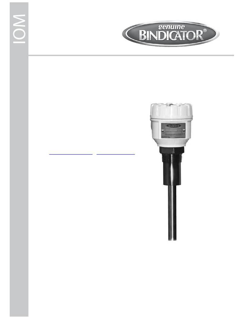
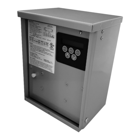
Bindicator SonoTracker Ultrasonic Liquid Level User manual

IOM
SON280020 Rev. C
SonoTracker Ultrasonic
Liquid Level
Installation & Operation Manual


I. HANDLING AND STORAGE......................................................................................................................................................................1
II. GENERAL SAFETY........................................................................................................................................................................................2
III. PRODUCT DESCRIPTION ..........................................................................................................................................................................3
IV. MECHANICAL INSTALLATION .................................................................................................................................................................6
General Installation Guidelines
Mounting Transducers
Mounting Temperature Probe
Drilling Holes In The Enclosure
Prepare The Enclosure For Conduit
Mounting Junction Box
Mounting Controller
V. ELECTRICAL INSTALLATION..................................................................................................................................................................16
General Safety
Disconnect Requirements For Permanently Installed Equipment
Wiring Transducer and Temperature Probe to Junction Box
Wiring Junction Box to Controller
Synchronization of Transducers
VI. SET-UP..........................................................................................................................................................................................................29
Setting Serial Addresses
Installing PCBs
Menu Tree
Operating the SonoTracker Series in Level Applications
SonoTracker Series Menu Descriptions
VII. MAINTENANCE .........................................................................................................................................................................................79
VIII. TROUBLESHOOTING...............................................................................................................................................................................80
SonoTracker Ultrasonic Liquid Level
Installation & Operation Manual
CONTENTS

SAFETY SYMBOLS
WARNING:
IDENTIFIES CONDITIONS OR PROCEDURES, WHICH IF NOT FOLLOWED,
COULD RESULT IN SERIOUS INJURY. RISK OF ELECTRICAL SHOCK.
CAUTION:
IDENTIFIES CONDITIONS OR PROCEDURES, WHICH IF NOT FOLLOWED,
COULD RESULT IN SERIOUS DAMAGE OR FAILURE OF THE EQUIPMENT.

I. HANDLING AND STORAGE
SAVE THESE INSTRUCTIONS
INSPECTIONS AND HANDLING
Do not dispose of the carton or packing materials.
Each package should be inspected upon receipt for damage that may have occurred due to mishandling during
shipping. If the unit is received damaged, notify the carrier or the factory for instructions. Failure to do so may
void your warranty. If you have any problems or questions, consult Customer Support at 800-778-9242.
DISPOSAL AND RECYCLING
This product can be recycled by specialized companies and must not be disposed of in a municipal collection
site. If you do not have the means to dispose of properly, please contact for return and disposal instructions or
options.
STORAGE
If the device is not scheduled for immediate installation following delivery, the following steps should be
observed:
1. Following inspection, repackage the unit into its original packaging.
2. Select a clean dry site, free of vibration, shock and impact hazards.
3. If storage will be extended longer than 30 days, the unit must be stored at temperatures between
32º and 104º F (0º to 40° C) in non-condensing atmosphere with humidity less than 85%.
CAUTION: DO NOT STORE A NONPOWERED UNIT OUTDOORS FOR A PROLONGED PERIOD.
SonoTracker Ultrasonic Liquid
Level & Open-Channel
Flow Controller
Installation & Operation Manual
1
www.bindicator.com
SON280020 Rev. C

II. GENERAL SAFETY
AUTHORIZED PERSONNEL
All instructions described in the document must be performed by authorized and qualied service personnel
only. Before installing the unit, please read these instructions and familiarize yourself with the requirements and
functions of the device. The required personal protective equipment must always be worn when servicing this
device.
USE
The device is solely intended for use as described in this manual. Reliable operation is ensured only if the
instrument is used according to the specications described in this document. For safety and warranty reasons,
use of accessory equipment not recommended by the manufacturer or modication of this device is explicitly
forbidden. All servicing of this equipment must be performed by qualied service personnel only. This device
should be mounted in locations where it will not be subject to tampering by unauthorized personnel.
MISUSE
Improper use or installation of this device may cause the following:
• Personal injury or harm
• Application specic hazards such as vessel overll
• Damage to the device or system
If any questions or problems arise during installation of this equipment, please contact Customer Support at
800-778-9242.
2
www.bindicator.com
SON280020 Rev. C

III. PRODUCT DESCRIPTION
The SonoTracker Series Ultrasonic System can monitor up to a total of 8 transducers of various frequencies,
accommodating multiple vessels of dierent heights and shapes.
The high scan rates of the SonoTracker Series provide fast information updates on material level. The
SonoTracker Series has an integral keyboard and a display that provide easy access for programming and allows
the user to input their own vessel identications. The enclosure is designed for rugged, outdoor applications and
is wall-mounted. The SonoTracker Series is available in AC and DC powered versions.
OPERATING PRINCIPLE OF ULTRASONIC MEASUREMENT
The operating principle of ultrasonics is based on the reection of sound, which is used in many applications to
determine distance. The transducer sends out a sound pulse through the air and then receives an echo a short
time later. The time is carefully measured, allowing the distance to the reecting object to be determined.
SYSTEM APPLICATIONS
The SonoTracker Series can be used in three ways:
1. Level
• Monitors level from up to 8 transducers.
• Can display volume or weight converted from level.
2. Flow
• Monitors up to 4 sensors.
• Measures ow using umes, weirs and nozzles
Note: The SonoTracker Series can monitor level, with a maximum of 8 transducers.
3
www.bindicator.com
SON280020 Rev. C

CONTROLLER SPECIFICATIONS
FUNCTIONAL
Operating Power 110/230 VAC (+/- 10%) 50/60 Hz or 24 VDC
Power Requirement 20 VA
Operating Temperature -5º to 122º F (-20º to 50º C)
Measuring Distance 1 to 125 ft (0.3 to 38 m) depending on sensor
PERFORMANCE
Transducer Compatibility Frequencies from 10 KHz to 45 KHz
Memory Non-volatile RAM, common isolation parameter storage
Relay Output
Form“C”SPDT, programmable, 10 A 110 VAC, 8 A 230 VAC non-inductive, 10 A 30 VDC;
available as plug in modules of 2, 4, 5 and 8 relays each
4-20 mA option: Isolated 600 ohms maximum or externally powered to 1000 ohms, 12 bit resolution;
available as plug in modules of 2, 4, and 8 outputs with common isolation;
must be installed in third option slot
Combi-Card option: One combi-card per unit; combinations are 2 relays, 1 current; or 4 relays, 2 currents
PLC Interface Option 32 channel block transfer, 6 channel discreet transfers, Probus-DP Slave
PHYSICAL
Enclosures NEMA 4X berglass reinforced polyester (FRP) or NEMA 4X Stainless Steel
Display Large, back lit alphanumeric liquid crystal, two lines of 16 characters, user programmable IDs, selectable bar
graph display or engineering units formats
TRANSDUCER SPECIFICATIONS
NOMINAL
RANGE
LIQUIDS
NOMINAL
RANGE
SOLIDS
MINIMUM
RANGE
TEMPERATURE
RANGE FREQUENCY BEAM ANGLE
BT-26T 25’(7.6m) 15’(4.6m) 12”(305 mm) -40° to 160°F
(-40° to 71°C) 43KHz 12° included
BT-26ST* 25’ (7.6m) 15’ (4.6m) 12” (305 mm) -40° to 230°F
(-40° to 110°C) 43KHz 12° included
BT-61PT 50’(15.2m) 30’(9.2m) 24”(610 mm) -40° to 160°F
(-40° to 71°C) 22KHz 12° included
BT-55 100’(30.5 m) 50’grains
100’plastics 24” (610 mm) -40° to 230°F
(-40° to 110°C) 24KHz 12° included
BT-101PT 125’(38.1 m) 100’(30.5 m) 36”(914 mm) -40° to 230°F
(-40° to 110°C) 14KHz 12° included
* 3A Approved (Transducer Specic)
4
www.bindicator.com
SON280020 Rev. C

Figure 1. SonoTracker Series Ultrasonic System Conguration Diagram
5
www.bindicator.com
SON280020 Rev. C

IV. MECHANICAL INSTALLATION
GENERAL INSTALLATION GUIDELINES
• Aim the transducer perpendicular to the surface of liquids.
• Provide sucient exible conduit at the transducer location to facilitate transducer aiming movement
and removal.
• Run transducer cable from the transducer to the junction box, and from the junction box to the controller
in dedicated grounded metal conduit or in cable tray. All cables connected to the same controller may be
routed in the same conduit.
WARNING: DO NOT RUN TRANSDUCER CABLE WITH ANY OTHER AC POWER WIRING.
MOUNTING INSTRUCTIONS
To congure the full system, the following will need to be mounted and/or installed
1. Transducer into the tank or vessel
2. Temperature Probe (optional)
3. Junction Box
4. SonoTracker Controller
MOUNTING TRANSDUCERS
For optimum results, a clear sound beam path between the transducer and the lowest level of material is
required. See Figure 2: Positioning Transducers for Optimum Results with Level Applications. When selecting a mounting
location for the transducer, follow these guidelines:
• Minimum distance from the transducer to any sidewall is the greater of the following:
— 1’(0.30m) horizontal distance for each 10’ (3.0m) in vertical distance from the face of the transducer
to the zero level (no material in the vessel)
— 2’(0.60m) horizontal distance
Note: For a very deep vessel with a small cross-section, it may be impossible to meet the above requirements.
• Transducer beam path is outside the path of the ll stream.
• Transducer beam path is away from splashing or agitating liquid or bouncing materials.
• Ladders, seams, rebar, etc. in the transducer beam path are avoided or eliminated.
• Transducer location is away from equipment which create vibration and noise that can interfere with the
operation of the system: dryers, motors, compressors, fans, blowers, air conditioning units, etc.
• Face of the transducer is above the maximum expected material level by a minimum of:
— 12”(305 mm) for 56T-25 transducers
— 24”(610 mm) for 56T-50 transducers
6
www.bindicator.com
SON280020 Rev. C

This is required to avoid having material within the transducer’s blind space (amount of time required for
transducer vibration to decay to a level where ultrasonic measurement is possible).
7
www.bindicator.com
SON280020 Rev. C

MOUNTING TEMPERATURE PROBE
Location Guidelines:
• Ensure that the temperature probe does not come in contact with the liquid during normal ll and during
overll conditions. The probe may be damaged if it comes in contact with the liquid during these
conditions.
• Temperature probe may be mounted pointing in any direction.
• Mount the temperature probe so that an average or representative air temperature in the vessel is read.
• Temperature probe has a 1/4”NPT mount. It can be mounted on the same ange with the transducer or
through use of a small bracket that will allow for a hanger type mounting within the vessel.
• Many users nd it convenient to mount the temperature probe near the transducer. If mounted in this
way, the temperature probe cable can be run through the same conduit as the transducer cable.
DRILLING HOLES IN THE ENCLOSURE
If the standard berglass NEMA 4X rated enclosure has no openings or pre-drilled punch-outs through which
to route cables or install the conduit, holes will need to be drilled. Hole location is critical for proper conduit
installation. Check clearances to ensure that the ttings and wire routing will not interfere with the PCB or
enclosure door.
PREPARE THE ENCLOSURE FOR CONDUIT
1. Open door of the enclosure.
2. Remove all four (4) mounting screws that attach the plate to the enclosure.
3. Remove entire frame, and place in a safe location.
4. Drill holes for wiring and cables. Holes should be made in the front 2 inches of the the bottom of the
enclosure (see Drawing SK90010); this allows for appropriate spacing for the unit and cables.
4.1. Make a hole for AC cable and relay wiring.
4.2. Make a hole for sensor cable.
4.3 Make a hole for 4-20mA wiring.
5. Clean enclosure of any debris; replace the plate back into the enclosure, using all four (4) mounting
screws.
6. Determine desired location for mounting the unit.
MOUNTING JUNCTION BOX
Mount the junction box close enough to the transducer to use the supplied 10’(3.0 m) transducer cable without
splicing. Mount the junction box so that water cannot reach the terminal block.
1. See Figure 3: Junction Box Mounting and Wiring. Hold the junction box at the desired location and mark
the positions of the mounting holes. Place the junction box in a safe place.
8
www.bindicator.com
SON280020 Rev. C

2. Drill the mounting holes.
3. Attach the junction box using hardware that will secure it rmly in place.
Note: Mounting hardware for the junction box is not supplied by Bindicator.
MOUNTING CONTROLLER
When mounting the controller, be sure there is enough clearance to open the front door completely. Removal and
insertion of the modular PCBs and wiring of the transducers and the PCBs are done through the front of the unit.
Do not mount the controller near high power equipment, contractors, SCR drives, 440 V lines, etc. The controller
enclosure dimensions are shown in Appendix E, Technical Drawings. Refer to Appendix A for environmental
specications before mounting the unit.
Follow this procedure to mount the controller:
1. Hold the controller enclosure against the wall in the desired location and mark the positions of the
mounting holes. Place the controller in a safe place.
2. Drill the mounting holes in the wall.
3. Attach the controller to the wall using hardware that will secure it rmly in place.
Note: Mounting hardware for the controller is not supplied by Bindicator.
9
www.bindicator.com
SON280020 Rev. C

10
www.bindicator.com
SON280020 Rev. C

11
www.bindicator.com
SON280020 Rev. C

12
www.bindicator.com
SON280020 Rev. C

13
www.bindicator.com
SON280020 Rev. C

14
www.bindicator.com
SON280020 Rev. C

15
www.bindicator.com
SON280020 Rev. C

16
www.bindicator.com
SON280020 Rev. C
Table of contents
Other Bindicator Measuring Instrument manuals
Popular Measuring Instrument manuals by other brands

Xylem
Xylem YSI ProQuatro Professional Series user manual

ZIEHL
ZIEHL TR640IP operating manual

GHM
GHM Delta OHM LPPYRA12 operating manual
Holzworth Instrumentation
Holzworth Instrumentation HA7062D user manual

Gemu
Gemu 1201 Installation, operating and maintenance guide
Diesse
Diesse VES-MATIC EASY Service manual
