Bindicator Pulse Point LP-500ST User manual

Pulse Point™ LP-500ST
Installation & Operation Manual
IOM
O
Or
rd
de
er
r
f
fr
ro
om
m:
:
C
C
A
A
B
Br
ri
ig
gg
gs
s
C
Co
om
mp
pa
an
ny
y
622 Mary Street; Suite 101; Warminster, PA 18974
Phone: 267-673-8117 - Fax: 267-673-8118
www.cabriggs.com


CONTENTS
I. HANDLING AND STORAGE............................................................................................................................................................................1
Inspection and Handling
Disposal and Recycling
Storage
II. GENERAL SAFETY............................................................................................................................................................................................2
Authorized Personnel
Use
Misuse
III. PRODUCT DESCRIPTION..............................................................................................................................................................................3
Function
Applications
Features
Technical Specications
Figure 1: Temperature Table
Figure 2: Temperature Graph
IV. MECHANICAL INSTALLATION ....................................................................................................................................................................5
Guidelines
Mounting Considerations
Figure 3: High/Low Level Location
Figure 4: Mounting Position
V. ELECTRICAL INSTALLATION.........................................................................................................................................................................7
General Safety
Disconnect Requirements for Permanently Installed Equipment
Protective Earth Ground
Electrical Connections
Figure 5: Wiring
Figure 6: Fail-Safe Operation
VI. MAINTENANCE ...............................................................................................................................................................................................9
Preventative Maintenance
VII. TROUBLESHOOTING .................................................................................................................................................................................9
VIII. DIMENSIONAL DRAWINGS ..................................................................................................................................................................10
Pulse Point™ LP-500ST
Installation & Operation Manual

SAFETY SYMBOLS
WARNING:
IDENTIFIES CONDITIONS OR PROCEDURES, WHICH IF NOT
FOLLOWED, COULD RESULT IN SERIOUS INJURY.
CAUTION:
IDENTIFIES CONDITIONS OR PROCEDURES, WHICH IF NOT
FOLLOWED, COULD RESULT IN SERIOUS DAMAGE OR FAILURE OF
THE EQUIPMENT.

www.bindicator.com
I. HANDLING AND STORAGE
SAVE THESE INSTRUCTIONS
INSPECTION AND HANDLING
Do not dispose of the carton or packing materials.
Each package should be inspected upon receipt for damage that may have occurred due to mishandling
during shipping. If the unit is received damaged, notify the carrier or the factory for instructions. Failure to
do so may void your warranty. If you have any problems or questions, consult the manufacturer Customer
Support at 1-800-778-9242.
DISPOSAL AND RECYCLING
This product can be recycled by specialized companies and must not be disposed of in a municipal collection
site. If you do not have the means to dispose of properly, please contact the manufacturer for return and
disposal instructions or options.
STORAGE
If the product is not scheduled for immediate installation following delivery, the following steps should be
observed:
1. Following inspection, repackage the unit into its original packaging.
2. Select a clean dry site, free of vibration, shock and impact hazards.
3. If storage will be extended longer than 30 days, the unit must be stored at temperatures between -31
to 140° F (-35 to 60° C) in non-condensing atmosphere with humidity less than 98%.
CAUTION: DO NOT STORE A NONPOWERED UNIT OUTDOORS FOR A PROLONGED PERIOD.
Pulse Point™ LP-500ST
Installation & Operation Manual
1

www.bindicator.com
II. GENERAL SAFETY
AUTHORIZED PERSONNEL
All instructions described in the document must be performed by authorized and qualied service personnel
only. Before installing the unit, please read these instructions and familiarize yourself with the requirements and
functions of the device. The required personal protective equipment must always be worn when servicing this
device.
USE
The device is solely intended for use as described in this manual. Reliable operation is ensured only if the
instrument is used according to the specications described in this document. For safety and warranty reasons,
use of accessory equipment not recommended by the manufacturer or modication of this device is explicitly
forbidden. All servicing of this equipment must be performed by qualied service personnel only. This device
should be mounted in locations where it will not be subject to tampering by unauthorized personnel.
MISUSE
Improper use or installation of this device may cause the following:
• Personal injury or harm
• Application specic hazards such as vessel overll
• Damage to the device or system
If any questions or problems arise during installation of this equipment, please contact the manufacturer
Customer Support at 800-778-9242.
2

www.bindicator.com
III. PRODUCT DESCRIPTION
FUNCTION
The LP-500ST is a vibrating rod, level measuring switch suitable for low and high level indication of granules and
powders with a minimum density of 3.12 lbs/ft3(0.05 kg/dm3density), using vibratory technology.
APPLICATIONS
Unlike radio frequency and capacitance technology sensors, the LP-500ST vibrating probe senses material using
a mechanical principle and is therefore not aected by the dielectric constant of the material. This makes it an
ideal sensor in plastics, dust, shavings, cement, lime, sand, grain, feed, sugar, etc.
FEATURES
• Universal power supply: AC or DC
• No calibration required
• Adjustable sensitivity
• Fine polished probe
TECHNICAL SPECIFICATIONS
FUNCTIONAL
Power Requirements 20 to 255 V AC/DC
Power Consumption ≤ 2.5 VA/2 W
Temperature See Figure 1
Outputs Main Relay: 8A SPDT @ 250 VAC, AC1
PERFORMANCE
Pressure Rating 362 psi (25 bar); cable extended 87 psi (6 bar)
Time Delay Field adjustable; 2 or 5 seconds
Fail Safe Field selectable, high/low level
Sensitivity 3.12 lbs/ft3(0.05 kg/dm3)
Maximum Particle Size 10mm
PHYSICAL
Enclosure Material, Rating Powder Coated Aluminum , IP67, NEMA 6
Conduit Entry
(2)
1/2”NPT;
(2) M20 x 1.5
Process Connections 11/2”NPT
Maximum Insertion Length (std unit) 8.15 in. (207 mm)
Shipping Weight (standard unit) 4.14 lb (1.88 kg)
3

www.bindicator.com
Figure 1: Temperature Table
Figure 2: Temperature Graph : Ambient Temperature Ta versus Medium Temperature Tm
TEMPERATURE DATA STANDARD AND PIPE EXTENDED VERSION CABLE EXTENDED VERSION
HIGH TEMP
Medium Temperature
Min -22º F (-30º C)
140º F
(60º C)
158º F
(70º C)
203º F
(95º C)
230
º F
(110º C)
320º F
(160º C)
140º F
(60º C)
158º F
(70º C
203º F
(95º C)
Ambient Temperature Range
Min -22º F (-30º C) 140º F
(60º C)
122º F
(50º C)
140º F
(60º C)
122
º F
(50º C)
95º F
(35º C)
140º F
(60º C)
122º F
(50º C)
140º F
(60º C)
Max. Surface Temperature
of Process Connection 185º F
(85º C)
185º F
(85º C)
203º F
(95º C)
203
º F
(95º C)
275º F
(135º C)
185º F
(85º C)
185º F
(85º C)
203º F
(95º C)
Max. Surface Temperature 185º F
(85º C)
185º F
(85º C)
203º F
(95º C)
230
º F
(110º C)
320º F
(160º C)
185º F
(85º C)
185º F
(85º C)
203º F
(95º C)
4

www.bindicator.com
IV. MECHANICAL INSTALLATION
GUIDELINES
The following precautions should be observed when installing and operating the product:
• The installation and wiring of this product must comply with all national, federal, state, municipal and
local codes that apply.
• This product is a precision device - handle the device with great care, especially the sensing probe.
• Any impact on the sensing probe may ruin its resonance system.
• A protective shield should be installed if the probe is exposed to falling material or excessive mechanical
load.
MOUNTING CONSIDERATIONS
Prior to installation, it is advised to check the switching function for proper adjustment on a sample quantity of
material. The unit may not work with mediums within the specied density range but having very large size of
granules or extremely little friction.
Screw in the device by its hexagon neck. After screwing tight the process connection, the housing can be
rotated (max. 300°), to adjust the cable gland to the required position. It might be necessary to install the device
at an oset level position relative to the switching level actually required taking into account angle of repose of
the material in the silo, see Figure 3.
Figure 3: High/Low Level Location
High Level Location Low Level Location
WARNING: REMOVE POWER FROM THE UNIT BEFORE INSTALLING, REMOVING, OR MAKING
ADJUSTMENTS
CAUTION: ATTEMPTING TO TIGHTEN THE LP500ST BY ROTATING THE HOUSING OR ROD
MAY DAMAGE THE UNIT AND VOID THE WARRANTY.
5

www.bindicator.com
Figure 4: Mounting Position
With powder level detection, device should be installed at an inclination exceeding the angle of repose (or, in
case of high level detection vertically), to prevent powder deposition on vibrating rod that might substantially
reduce the self-cleaning eect. Also avoid mounting the rod in a recess, see Figure 4.
In case of tanks that are likely to be exposed to intense vibrations, necessary provisions shall be made by the customer for
damping the vibrations acting on the device (e.g. vibration damping inserts made of rubber have to be applied).
6

www.bindicator.com
V. ELECTRICAL INSTALLATION
GENERAL SAFETY
When using electrical equipment, you should always follow basic safety precautions, including the following:
• The installation and wiring of this product must comply with all national, federal, state, municipal, and
local codes that apply.
• Do not modify any factory wiring. Connections should only be made to the terminals described in this
section.
PROTECTIVE EARTH GROUND
To eliminate shock hazards in the unlikely event of an internal insulation breakdown, the unit is provided with a
“protective earth” ( ) lead which must be connected to earth ground. In addition, the input power ground
lead must be connected to the “protective earth”( ) terminal provided. Wire sizes must be selected such that
it can safely carry the sum total of all circuits’maximum amperage.
ELECTRICAL CONNECTIONS
Note: The LP-500ST model can be operated from 20-255 V AC/DC and provides reverse polarity protection in
the event of a wiring error.
1. Remove the top cover of the housing to access the connection terminals and adjusting switches.
2. Do not remove the wire form terminal pin 1, see Figure 5, because it is an internal connection. For
grounding the unit, use the PE grounding screw terminal PE.
3. After proper installation and the electrical connection, established the device is ready for operation. The
switched-on state is indicated by the lighting of the LED.
The DENSITY (switch A) switch is to be set in accordance with the density of the material:
• LOW position, recommended for loose and light materials with density below 3.12 lbs/ft3(0.05 kg/dm3)
represents small energy and amplitude of vibration as well as great sensitivity of detection.
• HIGH position, recommended for (thick and heavy) materials with density over 6.24 lbs/ft3(0.1 kg/dm3)
represents vibration with great energy and amplitude and small sensitivity of detection
The instrument may not switch correctly in mediums with density less than 3.12 lbs/ft3(0.05 kg/dm3) or with
very small internal friction.
To obtain FAIL SAFE alarm (switch C), use the de-energized or open state of the output as an alarm, thus a
power breakdown will also be considered as alarm, see Figure 6.
The delay (switch B) is to be selected to comply with requirements of the process control technology the
units are used for.
WARNING: VERY HIGH VOLTAGE IS PRESENT ON THE ROD. REMOVE POWER
FROM THE UNIT BEFORE INSTALLING, REMOVING, OR MAKING ADJUSTMENTS
CAUTION: ATTEMPTING TO TIGHTEN THE ST1000 BY ROTATING THE HOUSING OR ROD
MAY DAMAGE THE UNIT AND VOID THE WARRANTY
7

www.bindicator.com
Power Probe Fail Safe Mode LED Relay Solid State
Output
On
Not Vibrating
(Covered)
Low Green Energized On
High Red De-Energized O
Vibrating (Free) Low Red Energized O
High Green Energized On
Fails
Low or High Not Lit De-Energized O
54
6
54
6
54
6
54
6
54
6
6
45
2, 7 k
6
45
2, 7 k
6
45
2, 7 k
6
45
2, 7 k
6
45
2, 7 k
N
L1
PE
Device
to be
controlled
+5 V
IN
GND
50VAC
350mA
2,7k
N1L1
Status LED A B C
N
L1
PE
50VAC
350mA
2,7k
N1L1
Status LED
Overload LED
A B C
N
L1
PE
≤ 5 W
50VAC
350mA
2,7k
N1L1
Status LED
Overload LED
A B C
Status LED
N L1
PE PE
NO CNC
N1L1
250VAC
8A/AC1
A B C
Wiring of optional coupled sink input to solid state
output version supplied from an AC line
Wiring of a load to a solid state output version supplied
from an AC line
Wiring of relay output version
Wiring of a logical voltage input to a solid state ouput
version supplied from an AC line
Figure 6. Fail-Safe Operation
Figure 5.
8

www.bindicator.com
VI. MAINTENANCE
PREVENTATIVE MAINTENANCE
The LP-500ST model does not require maintenance on a regular basis. In some instances, however, the vibrating
section may need a cleaning from deposited material. This must be carried out gently, without harming the
vibrating section of the vibrating rod.
VII. TROUBLESHOOTING
Contact your local factory representative if additional assistance is needed. Please provide the following
information:
• Model number
• Date of Purchase
• Application information (type of material, mounting conguration, etc.)
• Description of problem
If your local representative is unable to determine the cause of diculty, you will be referred to a factory engineer.
Equipment shipped back to the factory without proper authorization will be refused and returned at the shipper’s
expense.
9

www.bindicator.com
VIII. DIMENSIONAL DRAWINGS
Values in inches (mm)
Standard
2 x M20 x 1.5
S = 46
3.5 (90)
8.1 (207)
4.6 (116)
5.2 (133)
2 x NPT 1/2”
11/2” BSP /
11/2” NPT
2 x M20 x 1.5
S = 46
3.5 (90)
1.0 - 9.8 ft (0.3 - 3 m)
4.6 (116)
5.2 (133)
2 x NPT 1/2”
11/2” BSP /
11/2” NPT
Pipe Extension
2 x M20 x 1.5
S = 46
3.5 (90)
3.2 - 65 ft (1 - 20 m)
4.6 (116)
5.2 (133)
2 x NPT 1/2”
11/2” BSP /
11/2” NPT
Cable Extension
10


150 Venture Boulevard
Spartanburg, SC 29306
Tel: (800) 778-9242
Fax: (864) 574-8063
sales@bindicator.com
www.bindicator.com
2015 All rights reserved.
All data subject to change without notice.
STS180212 Rev C
Table of contents
Other Bindicator Measuring Instrument manuals

Bindicator
Bindicator Pulse Point II Series User manual

Bindicator
Bindicator MP Series User manual

Bindicator
Bindicator PRD1000 User manual
Bindicator
Bindicator SonoTracker Ultrasonic Liquid Level User manual
Bindicator
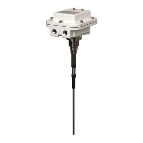
Bindicator VRF-2000R Series User manual
Bindicator
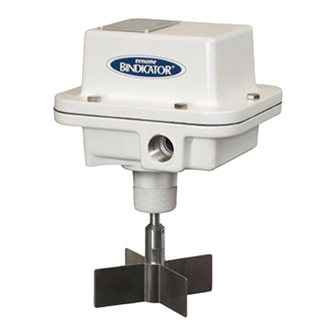
Bindicator Roto-Bin-Dicator User manual
Popular Measuring Instrument manuals by other brands
Bresser
Bresser 40-25860 instruction manual
EUTECH INSTRUMENTS
EUTECH INSTRUMENTS WATERPROOF PHSCAN 2 PH TESTER manual

Akron Brass
Akron Brass AkroFlow 9301 Installation, operating and maintenance instructions

wattwatchers
wattwatchers A6M+One installation guide

Dakota Digital
Dakota Digital Odyssey II Series quick start guide
LI-COR
LI-COR LI-800 Replacement instructions
