BC Biomedical ESU-2400 User manual

ELECTROSURGICAL
UNIT ANALYZER
ESU-2400 Series
USER MANUAL


i
WARNINGS, CAUTIONS, NOTICES........................................................................... iii
DESCRIPTION............................................................................................................. 1
Accessories .............................................................................................................. 3
OVERVIEW.................................................................................................................... 7
TYPICAL MEASUREMENT CONNECTIONS.................................................................8
Monopolar .................................................................................................................8
Bipolar........................................................................................................................9
External Loads.........................................................................................................10
Tissue Response Test............................................................................................. 12
Leakage Mode 1a....................................................................................................13
Leakage Mode 1b....................................................................................................14
Leakage Mode 2...................................................................................................... 15
Leakage Mode 3...................................................................................................... 16
GETTING STARTED
ForceTriad™Preventative Maintenance.................................................................. 17
Measure RF Energy
Scenario 1: Measure mA, 500 ohm load, manual DUT trigger.............................. 18
Scenario 2: Measure mA and Watts, 300 ohm load, footswitch triggers DUT.......20
Scenario 3: Measure Hyfrecator mA, 200 ohm load, manual DUT trigger ............ 23
Scenario 4: Measure mA and kHz, 200 ohm load, manual DUT, Pulse Mode 1 ... 25
Scenario 5: Measure V, Delayed Mode................................................................. 28
Measure RF Leakage
Leakage Test 1a: Active to Ground....................................................................... 31
Leakage Test 1b: Dispersive to Ground................................................................ 33
Leakage Test 2: Ground Referenced DUT, Active to Ground............................... 35
Leakage Test 3: Ground Referenced DUT, Dispersive to Ground........................ 37
REM/ARM/CQM Test
Scenario 1: Test REM at 35 ohms ........................................................................39
Scenario 2: Increase REM by 40% ....................................................................... 40
BC BIOMEDICAL
ESU-2400 SERIES
TABLE OF CONTENTS

ii
Load Curves
Scenario 1: Bipolar, 60W, 100 to 1000 ohms, auto trigger DUT............................ 41
Scenario 2: Pure Cut, 300W, Load List, manual trigger DUT................................ 44
Autosequence
RF Measure: 200 ohms, 315mA Limit, ±10mA...................................................... 47
Load Curve: Pure Cut, 300W, 50-5000 ohms, Manual Trigger ............................. 50
Auto CQM ............................................................................................................. 52
MAIN SCREEN ............................................................................................................. 54
AUTOSEQUENCES...................................................................................................... 57
Running the Autosequence ................................................................................ 74
Autosequence Results....................................................................................... 78
MEASURE RF ENERGY.............................................................................................. 79
Tissue Response Test........................................................................................ 80
Parameter Descriptions...................................................................................... 82
Graph Screen..................................................................................................... 85
Footswitch Configuration.................................................................................... 87
ESU-2400H Advanced Input Modes................................................................... 89
POWER LOAD CURVES............................................................................................. 97
REM/ARM/CQM......................................................................................................... 104
MEASURE RF LEAKAGE.......................................................................................... 105
SYSTEM TOOLS ....................................................................................................... 112
Transfer Files.................................................................................................... 112
Time and Date Setup....................................................................................... 113
Touchscreen Calibration.................................................................................. 114
System Setup.................................................................................................. 115
System Version and Updates.......................................................................... 116
Networking....................................................................................................... 121
Remote Mode................................................................................................... 122
Internet Access................................................................................................ 124
RS-232 Terminal .............................................................................................. 124

iii
COMMON DIALOG SCREENS.................................................................................. 126
File Open......................................................................................................... 126
File Save ......................................................................................................... 127
Keypad............................................................................................................ 128
Numpad........................................................................................................... 129
Print................................................................................................................. 130
KEYBOARD / MOUSE............................................................................................... 133
BARCODE SCANNER............................................................................................... 133
ERROR MESSAGES................................................................................................. 134
SYSTEM INPUTS AND OUTPUTS............................................................................ 137
DFA®TECHNOLOGY ............................................................................................... 139
FOOTSWITCH CONNECTOR.................................................................................... 140
COMMUNICATION PROTOCOL................................................................................ 141
COMMUNICATION COMMAND SUMMARY.............................................................. 148
FREQUENTLY ASKED QUESTIONS (FAQ) .............................................................. 162
MANUAL REVISIONS................................................................................................ 164
LIMITED WARRANTY................................................................................................ 164
SPECIFICATIONS ..................................................................................................... 166
NOTES....................................................................................................................... 174
CALIBRATION INTERVAL
To ensure the accuracy of the ESU-2400 Series
Analyzers, BC Group International, Inc.
recommends that it be calibrated at least once
every 12 months. Calibration must be done by
qualified personnel. Contact BC Group
International, Inc. for calibration.

iv
WARNING - USERS
The ESU-2400 Series is for use by
skilled technical personnel only.
WARNING - USE
The ESU-2400 Series is intended for testing only
and should never be used in diagnostics,
treatment or any other capacity where it would
come in contact with a patient.
WARNING - CONNECTIONS
All connections to patients must be removed
before connecting the DUT to the ESU-2400
Series. A serious hazard may occur if the patient
is connected when testing with the ESU-2400
Series. Do not connect any leads from the patient
directly to the ESU-2400 Series or DUT.
WARNING - POWER ADAPTOR
Unplug the Power Adaptor before
cleaning the surface of the ESU-2400 Series.
WARNING - MODIFICATIONS
The ESU-2400 Series is intended for use within
the published specifications. Any application
beyond these specifications or any unauthorized
user modifications may result in hazards or
improper operation.
WARNING - USE
Never touch exposed metal surfaces on test
leads or other current-carrying parts while the
DUT is activated.

v
WARNING - LIQUIDS
Do not submerge or spill liquids on the
ESU-2400 Series. Do not operate the ESU-2400
Series if internal components not intended for
use with fluids may have been exposed to fluid,
as the internal leakage may have caused
corrosion and be a potential hazard.

vi
CAUTION - SERVICE
The ESU-2400 Series is intended to be serviced
only by authorized service personnel.
Troubleshooting and service procedures
should only be performed by
qualified technical personnel.
CAUTION - ENVIRONMENT
Exposure to environmental conditions outside
the specifications can adversely affect the
performance of the ESU-2400 Series. Allow ESU-
2400 Series to acclimate to specified conditions
for at least 30 minutes before attempting to
operate it.
CAUTION - CLEANING
Do not immerse. The ESU-2400 Series should be
cleaned by wiping gently with a damp, lint-free
cloth. A mild detergent can be used if desired.
CAUTION - INSPECTION
The ESU-2400 Series should be
inspected before each use for wear and
the ESU-2400 Series should be serviced
if any parts are in question.
CAUTION - VENTILATION
The ESU-2400 Series includes ventilation slots to
help prevent overheating during operation and
should not be blocked.

vii
viii
NOTICE –SYMBOLS
Symbol Description
Caution
(Consult Manual for Further Information)
Per European Council Directive
2002/95/EC, do not dispose of this
product as unsorted municipal waste.
NOTICE –ABBREVIATIONS
AAMI
Association for the Advancement of Medical Instrumentation
Amps
Amperes
ANSI
American National Standards Institute
ARM™
Aspen Return Monitor
C
Celsius
CF
Crest Factor
CQM
Contact Quality Monitor
°
Degree
DFA
Digital Fast Acquisition
DUT
Device Under Test
hrs
Hours
Hz
Hertz
IEC
International Electrotechnical Commission
kg
Kilogram(s)
kHz
kilohertz
lbs
Pounds
MHz
Megahertz
mA
Milliampere(s)
mm
Millimeter(s)
ms
Millisecond(s)
mV
Millivolt(s)
Ω
Ohm(s)
PC
Personal Computer
Pk
Peak
REM
Return Electrode Monitor
RF
Radio Frequency
RMS
Root Mean Square
USA
United States of America
V
Volt(s)

ix
NOTICE –PERFORMING TESTS
REFER TO DUT MANUFACTURER’S SERVICE MANUAL FOR
TEST PROCEDURES AND MEASUREMENT LIMITS.
NOTICE –DISCLAIMER
USER ASSUMES FULL RESPONSIBILITY FOR UNAUTHORIZED
EQUIPMENT MODIFICATIONS OR APPLICATION OF EQUIPMENT
OUTSIDE OF THE PUBLISHED INTENDED USE AND
SPECIFICATIONS. SUCH MODIFICATIONS OR APPLICATIONS
MAY RESULT IN EQUIPMENT DAMAGE OR PERSONAL INJURY.
NOTICE –DISCLAIMER
BC GROUP INTERNATIONAL, INC. RESERVES THE RIGHT TO
MAKE CHANGES TO ITS PRODUCTS OR SPECIFICATIONS AT
ANY TIME, WITHOUT NOTICE, IN ORDER TO IMPROVE THE
DESIGN OR PERFORMANCE AND TO SUPPLY THE BEST
POSSIBLE PRODUCT. THE INFORMATION IN THIS MANUAL
HAS BEEN CAREFULLY CHECKED AND IS BELIEVED TO BE
ACCURATE. HOWEVER, NO RESPONSIBILITY IS ASSUMED
FOR INACCURACIES.
NOTICE –TRADEMARKS
Valleylab™, ForceTriad™, LigaSure™, REM™, and
ForceTriVerse™ are trademarks of Covidien.
Copyright © 2012 Covidien. All rights reserved. Reprinted
with the permission of the Surgical Solutions business unit of
Covidien.

x
ESU-2400 Series User Manual Copyright © 2017
www.bcgroupintl.com Made in the USA
11/17 Rev 10
NOTICE –CONTACT INFORMATION
BC BIOMEDICAL
BC GROUP INTERNATIONAL, INC.
3081 ELM POINT INDUSTRIAL DRIVE
ST. CHARLES, MO 63301
USA
1-800-242-8428
1-314-638-3800
www.bcgroupintl.com
sales@bcgroupintl.com
esu.bcgroupintl.com

1
This manual covers the model ESU-2400 and ESU-2400H Electrosurgical Unit Analyzers.
Throughout this manual the term ESU-2400 will be used to apply to both models. Sections
that are specific to the ESU-2400H model will use the term ESU-2400H exclusively.
The Model ESU-2400 Electrosurgical Unit Analyzer is a high-accuracy True RMS RF
Measurement system designed to be used in the calibration and routine performance
verification of Electrosurgical Generators. It offers a higher degree of accuracy than
previously attainable with conventional Electrosurgical Unit Analyzer designs. The ESU-
2400 provides an advanced low reactance internal load bank with a range of 0 to 6400
ohms in 1 ohm increments. It is microprocessor based and utilizes a combination of
unique hardware and software to provide accurate and reliable test results, even from
difficult waveforms such as “Spray”. The DFA Technology®utilized in the ESU-2400 and
DFA2Technology®(Patent Pending) utilized in the ESU-2400H allow the system to
aggressively digitize the complex RF waveforms produced by Electrosurgical Generators,
analyze each individual digital data point, and provide highly accurate measurement
results.
The ESU-2400, unlike many conventional ESU Analyzers, has internal high voltage setup
relays to control the measurement path, allowing the user to switch between Power
measurements, Leakage measurements, REM/ARM/CQM testing, or even run an
autosequence that could include any or all of these tests –without even moving wires
around!
The current transformer internal to the ESU-2400 senses the RF current flowing through
the internal test load and produces a ratiometric voltage which is digitized and analyzed
by the microprocessor. Combining the standard and low ranges of the ESU-2400 with the
use of the current transformer, the user has full control over the ability to get high accuracy
and high resolution readings from all types of Electrosurgical Generators.
BC BIOMEDICAL
ESU-2400
ELECTROSURGICAL UNIT ANALYZER

2
The following are highlights of some of the main features:
•TRUE RMS READINGS USING DFA® TECHNOLOGY
•INDUSTRY STANDARD CURRENT SENSING TECHNOLOGY
•mV, mV PEAK, mA, CREST FACTOR AND POWER (WATTS)
RANGES, LOAD VOLTAGE(ESU-2400H only)
•COLOR QVGA DISPLAY WITH TOUCHSCREEN
•1% OF READING MEASUREMENT ACCURACY
•DIGITAL CALIBRATION –NO POTS TO TURN
•SELECTABLE DISPLAY OPTIONS
•GRAPHICAL ON-SCREEN REPRESENTATION OF MEASURED
RF SIGNAL
•HIGH RANGE (1000 mV) AND LOW RANGE (100 mV) WITH
AUTOSCALING CAPABILITY
•PULSED RF WAVEFORM MEASUREMENT MODE FOR LOW
DUTY CYCLE PULSED OUTPUTS OFFERED BY SOME
ELECTROSURGICAL MANUFACTURERS
•PROGRAMMABLE AUTOSEQUENCES
•PROGRAMMABLE LOAD CURVES
•BUILT IN CQM TESTING WITH ONE OHM RESOLUTION
•TISSUE RESPONSE TESTING WITH GRAPHING CAPABILITY
•FOOTSWITCH OUTPUTS FOR TRIGGERING THE DUT
•ON-SCREEN DISPLAY OF MEASURMENT CONFIGURATION
•USB PORTS FOR KEYBOARD, MOUSE, PRINTER, OR FLASH
DRIVE.
•ETHERNET PORT FOR INCREASED ACCESSIBILITY
3
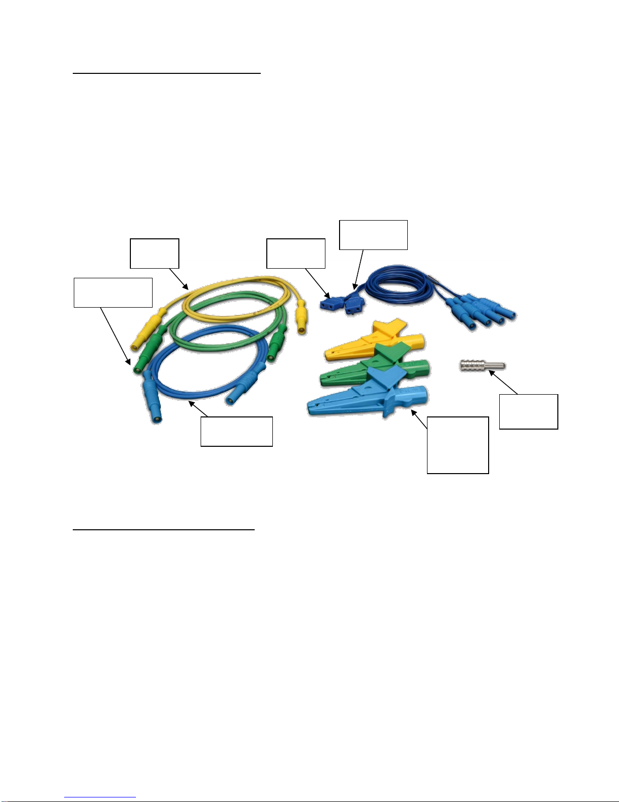
STANDARD ACCESSORIES:
BC20 –00130 Accessory Kit (Test Leads)
BC20 –21107 Universal Power Supply
BC20 –41341 Communications Cable (RS-232)
BC20 –205XX Standard Power Adapter
(International Options, See Page 138 For Details)
Standard Accessory Kit, BC20-00130:
OPTIONAL ACCESSORIES:
BC20 –00131 ForceTriad PM Accessory Kit
BC20 –00132 CONMED PM Kit
BC20 –00133 CONMED Automation Kit
BC20 –00140 Replacement packaging
BC20 –41360 Communications Cable, USB Null Modem
BC20 –00232 BNC To BNC Cable
BC20 –03000 Footswitch Cable, Unterminated
BC20 –03001 Footswitch Cable for Covidien ForceFx
BC20 –03002 Footswitch Cable for CONMED System 5000
BC20 –03003 Footswitch Cable for Covidien ForceTriad
BC20 –03004 Footswitch Simulator for Covidien ForceFx and
ForceTriad, triggers Cut, Coag, Bipolar
Ground
Lug
Active
Lead
CQM
Lead
Banana
Jack
Alligator
Clips
Earth/Ground
Lead
RECQM
Lead
Dispersive
Lead

4
BC20 –03005 Monopolar Hand Switch Simulator
BC20 –03006 Footswitch Cable for Olympus ESG-100
BC20 –03007 Footswitch Cable for Olympus ESG-400
TRL –2420 Tissue Response Load

5
OPTIONAL ACCESSORIES (continued):
Optional Accessory Kit, BC20-00131, ForceTriad PM Accessory Kit
BC20-03004
Footswitch Simulator
TRL-2420
Tissue Response Load
BC20-03005
Monopolar Handpiece
Simulator
Autobipolar
Lead
Cross Coupling
Lead
Carrying
Case
UFP Port
Adapter
External Cross
Coupling Load
Cross
Coupling
Lead

6
CQM Cable Differences –Two CQM cables are provided in the standard accessory kit.
The only difference between them is that one cable has a small pin and the other does
not. The cable with the pin is used to enable the REM circuitry on the DUT. The cable
without the pin is used to bypass the REM circuit and allow for shorting of the REM leads.
Note that some generators do not allow for the REM circuit to be disabled. For these
generators it does not matter which cable is used.
When using the ESU-2400 CQM test mode, the cable with the pin must be used.
For other modes, the Dispersive ports on the ESU-2400 are shorted together and the
cable without the pin should be used.
Cable Without Pin,
Disabled REM
Cable With Center
Pin, Enables REM

7
This section looks at the layout of the ESU-2400 and gives descriptions of the elements
that are present.
Swivel
Carrying
Handle
Computer Interface
Serial Port
2 USB Ports
10/100 Ethernet
Power
Kycon 3 position
locking
receptacle
QVGA
Display with
touchscreen
Durable Powder-Coated,
Custom Aluminum Case
Front USB Port
Power Switch
Rocker Switch
Oscilloscope
Output
Footswitch Interface
Automated DUT
Activation
Safety Jacks
RF Input
OVERVIEW
8
The ESU-2400 Series utilizes an internal current transformer and internal precision load
resistors for simple configuration of typical Electrosurgical Generator testing. Many of the
world’s leading Electrosurgical generator manufacturers utilize this exact same technique
when they test, service and calibrate their generators.
Internal configuration relays allow for simple connections to the DUT. When the Measure
RF Energy, Measure RF Leakage, or REM/ARM/CQM mode is selected from the main
menu, the relays configure the internal connections as required. Shown below are
examples of external connections to the DUT.
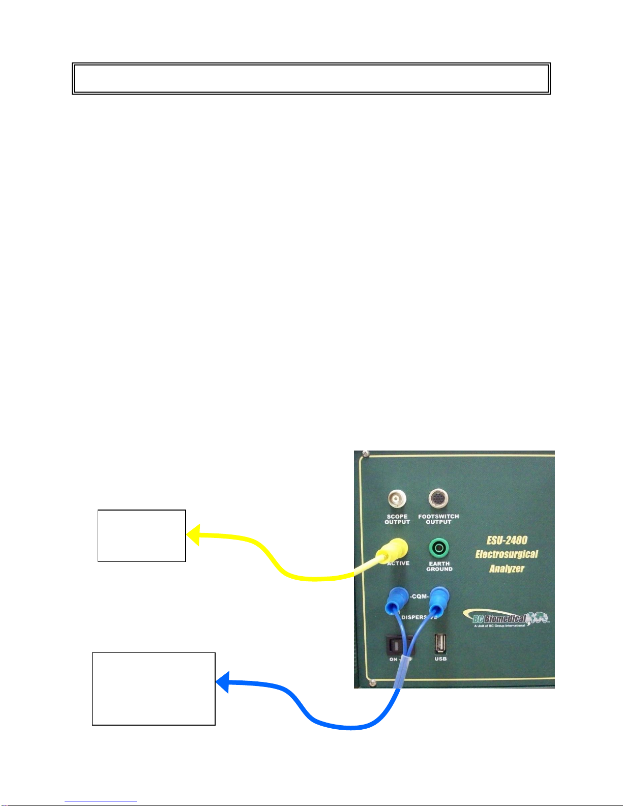
Monopolar:
1. Yellow Active Lead from Active Jack on ESU-2400 to DUT Output.
2. Blue Dispersive Lead from Dispersive Jack on ESU-2400 to DUT Dispersive.
TYPICAL MEASUREMENT CONNECTIONS
ESU (DUT)
Active
Electrode
ESU (DUT)
Patient Return/
Dispersive
Electrode
This manual suits for next models
1
Table of contents
Other BC Biomedical Measuring Instrument manuals

BC Biomedical
BC Biomedical DA-2006 User manual

BC Biomedical
BC Biomedical DPM-2001 User manual

BC Biomedical
BC Biomedical SPO-2000 User manual

BC Biomedical
BC Biomedical DPM-2350 SERIES User manual

BC Biomedical
BC Biomedical SA-2000-INTL User manual

BC Biomedical
BC Biomedical SA-2010 User manual

BC Biomedical
BC Biomedical SA-2500 User manual

BC Biomedical
BC Biomedical PFC-3000 SERIES User manual

BC Biomedical
BC Biomedical USP-100A User manual

BC Biomedical
BC Biomedical IPA-2000 User manual


