Bio Green Super Seeder User manual

ESFREN
Installation and operating instruction
Sowing machine
Instrucciones de instalación y funcionamiento Máquina sembradora
Notice de montage et d‘utilisation Semoir
SUPER SEEDER

2
1
abcd
g
ef
h
x
m
kz
m
k
a
b
ywv
4

3
x
m
e
f
2
4
5
z
m
h
dgac
yv
3
v
v
&
234
5 6
w
&
1
w
w

4
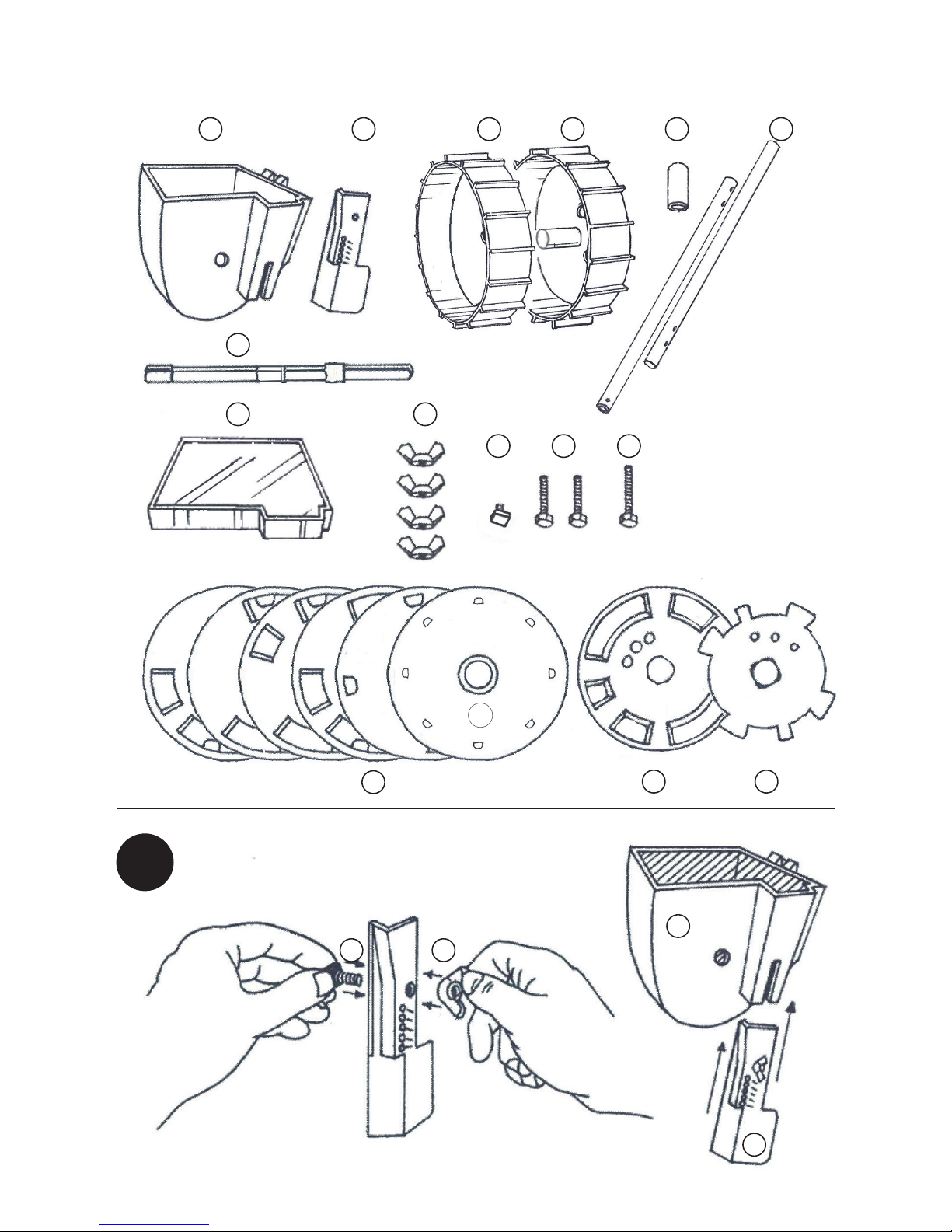
Before assembling the seeder (seed drill),
please make sure that all of the listed parts
are available. Please decide now what kind
of combination you would like to use for so-
wing: seeding disc or drive disc.
Please start with illustration (1), the sowing
plough, and mount the sowing plough (b)
to the seed hopper (a) with the appropriate
parts (k) & (m) and avoid tightening the wing
nut (m) too tight. This would make a subse-
quent adjustment of the sowing plough very
dicult. The number on the previously deter-
mined seeding disc must correspond to the
depth setting of the sowing plough. (Exam-
ple: seeding disc (4) = marking on sowing
plough “4”). Please insert the seeding disc
combination (y, v/w) into the seed hopper,
as it is shown in illustration (2), and subse-
quently connect the axle (g) and wheels (c,
d) according to illustration (3) with the seed
hopper.
The handlebars are connected with the two
screws (x) and wing nuts (m). The green cap
(e) will close the top of the pipe. Now, con-
nect the handlebar with the seed hopper
with the screw (z) and a wing nut (m). For
subsequent depth adjustments of the so-
wing plough, the wheel (d) must be removed.
When seeding discs of a small diameter are
used (seeding discs 5 & 6 for small seeds),
the sowing plough should be pushed up-
wards as far as possible. Once the sowing
plough setting is set, push the wheel (d)
firmly onto the shaft. Fill the seeds into the
hopper and close the seed hopper with the
plastic cover (h).
If the ground is hard, rocky or
it contains big lumps, you first
must prepare the bed with an
appropriate garden tool, before
you can use the seeder.
Sowing
Please, fill the seed hopper only up to the
bottom part of the axle with seeds. Push the
seeder at a normal walking pace forward.
Walk slower, when the container is almost
empty. The groove for the seeds should
be kept in a horizontal position. When the
ground is dry, and when you are sowing
extra large seeds, dip the handlebar slightly
downwards. Hint: Always use the transpa-
rent plastic cover for the seed hopper when
sowing.
Changing Seeding Discs
The wheels on the axle are pushed together
in such a way, that the long-axle can be
partially pulled out of the seeding groove.
This allows you to lift out the dispenser as
well as the seeding disc combination in or-
der to change the seeding distance or discs
respectively. Please be aware that the see-
ding depth needs to be adjusted correctly
according to the seeding disc (number).
Please, do not allow soil or rocks inside the
seed hopper. Other materials, such as seed
coatings (for example, pesticides) can also
prevent the seeder from operating properly.
Seeding discs that are not currently being
used, can be mounted to the outside of the
right wheel (by clicking them onto it).
EN Sowing machine
SUPER SEEDER
!

5
Seed disk Vegetables Perforations Row Distance Plant distance
Oset for
Nr. 1
Peas 8 50 cm
Beans 4(2) 50 cm
Sweet corn 2 50 cm (80 cm)
Nr. 2 Beetroots 4 30 - 40 cm 10 cm
Cucumbers 2 (4) 30 - 40 cm 20 cm
Nr. 3 Seed pills
Spinach 4/8 30 cm
Nr. 4 Radishes 8 20 cm
Nr. 5
Carrots 8 25 - 35 cm 2 - 3 cm
Parsley 8 30 - 40 cm
Lettuce 8 25 - 30 cm 20 cm
Nr. 6
Cabbage 2 (4) 40 - 60 cm 40 - 60cm
Onions 8 25 cm 5 cm
Leeks 4 30 cm 10 cm
Chicory 4 50 cm 10 cm
8
4
2
Distance disc – only for seed disc
Distance disc – only for seed disc -
8 perforations ≈ 5 cm
4 perforations ≈ 10 cm
2 perforations ≈ 20 cm
Offset for
plant distance:
1
23456

6
FR Semoir
SUPER SEEDER
Avant d’assembler le semoir, assurez-vous
que toutes les parties listées sont disponi-
bles. Choisissez la combinaison que vous
souhaitez utiliser pour semer: disque d’en-
semencement ou disque d’entrainement.
Commencez par la figure (1), le labour (b) et
installez-le sur la trémie (a) à l’aide des pie-
ces correspondantes (k) & (m) tout en évitant
de trop serrrer l’écrou papillon (m), ce qui
rendrait un réglage ulterieur du labour tres
dicile. Le chire sur le disque de semence
déterminé à l’avance doit correspondre à la
profondeur programmée du labour (exemple
: disque de semence (4) = marquage sur le
labour „4“). Veuillez insérer la combinaison
de disque de semence (y, v/w) dans la trémie
comme indiqué sur la figure (e), puis relier
l’axe (g) et les roues (c, d) selon la figure (3)
avec la trémie.
Les manches sont reliés par deux vis (x)
eet écrous papillon (m). Le bouchon vert (e)
ferme le haut du tube. Connectez mainte-
nant le manche à la trémie à l’aide de la vis
(z) et de l’écrou papillon (m). Pour des régla-
ges ultérieurs du labour, la roue (d) doit être
retiréée. Lorsque les disques de semoir d’un
diametre inferieur sont utilisés (disques de
semoir 5 & 6 pour petites grines), le labour
doit etre poussé autant que possible vers le
haut. Une fois le labour paramétré, poussez
la roue (d) fermeent sur l’arbre. Remplissez la
trémie de graines et fermez la trémie à l’aide
du couvercle en plastique (h).
Si le sol est dur, rocailleux ou
contient de gros morceaux, vous
devez tout d’abord préparer le lit
à l’aide d’un outil de jardinage ap-
proprié avant d’utiliser le semoir.
Semence
Remplissez la trémie de graines uniquement
jusqu’à la partie inférieure de l’axe. Poussez
le semoir en marchant en avant à vitesse
normale. Lorsque le réservoir est presque
vide, marchez plus lentement. La rainure à
graines doit être conservée en position ho-
rizontale. Lorsque le sol est sec et lorsque
vous semez de grosses graines, abaissez
légèrement le manche. Conseil: utilisez tou-
jours le couvercle en plastique transparent
de la trémie lorsque vous semez.
Changer les disques du semoir
Les roues de l’axe sont poussées l’une vers
l’autre de maniere à ce que l’axe long puis-
se etre partiellemnet tiré hors de la rainure
de semence. Ceci vous permet de soulever
le distributeur ainsi que la combinaison de
disque de semence pour modifier la distan-
ce de semence ou les disques. Notez que la
profondeur de semence doit être reglée cor-
retement en fonction du disque de semence
(chire). Ne laissez pas de terre ou pierres
pénétrer à l’intérieur de la trémie. D’autres
materiaux tels que les revetements de grines
(des pesticides, par exemple) peuvent aussi
empêcher le semoir de fonctionner correcte-
ment. Les disques de semence qui ne sont
pas utilisés peuvent être intallés sur l’exte-
rieur de la roue droite (en les clipant dessus).
!

7
Disque de
semis Légumes Trous Ecartement des
rangs
Ecart de plantation
Replanter pour le
Nr. 1
Petit pois 8 50 cm
Haricots 4(2) 50 cm
Maïs doux 2 50 cm (80 cm)
Nr. 2 Betteraves rouges 4 30 - 40 cm 10 cm
Concombres 2 (4) 30 - 40 cm 20 cm
Nr. 3 Pastilles de semis
Epinards 4/8 30 cm
Nr. 4 Radis 8 20 cm
Nr. 5
Carottes 8 25 - 35 cm 2 - 3 cm
Persil 8 30 - 40 cm
Salade 8 25 - 30 cm 20 cm
Nr. 6
Choux 2 (4) 40 - 60 cm 40 - 60cm
Oignons 8 25 cm 5 cm
Poireaux 4 30 cm 10 cm
Endives 4 50 cm 10 cm
8
4
2
Disque écarteur – uniquement pour le disque de semis
8 trous ≈ 5 cm
4 trous ≈ 10 cm
2 trous ≈ 20 cm
Replanter pour le
Ecart de plantation:
1
23456

8
ES Máquina sembradora
SUPER SEEDER
Antes de ensamblar la sembradora, por fa-
vor asegúrese de que todas las partes lis-
tadas están disponibles. Por favor decida
ahora qué tipo de combinación le gustaría
usar para la siembra: disco sembrador o dis-
co móvil.
Por favor comience con la ilustración (1), el
arado de siembra, y ensamble el arado de
siembra (b) en la tolva de semillas (a) con las
partes apropiadas (k) y (m) y evite apretar
demasiado la tuerca de mariposa (m). Esto
dificultaría mucho cualquier futuro ajuste
del arado de siembra. El número en el disco
sembrador previamente determinado debe
corresponder con la configuración de pro-
fundidad del arado de siembra. (Ejemplo:
disco sembrador (4) = marca en el arado de
siembra “4”). Por favor inserte la combinaci-
ón de disco sembrador (y, v/w) en la tolva de
semillas como se muestra en la ilustración
(2), y subsecuentemente conecte el eje (g)
y las ruedas (c, d) con la tolva de semillas
como se muestra en la ilustración (3).
Los manubrios están conectados con los
dos tornillos (x) y las tuercas de mariposa
(m). El tapón verde (e) cerrará la parte su-
perior del tubo. Ahora, conecte el manubrio
con la tolva de semillas con el tornillo (z) y la
tuerca de mariposa (m). Para ajustes futuros
de profundidad del arado de siembra, la rue-
da (d) debe ser removida. Cuando se usan
discos sembradores de diámetro pequeño
(discos sembradores 5 y 6 para semillas
pequeñas), el arado de siembra debería ser
empujado hacia arriba tanto como sea posi-
ble. Una vez que la configuración del arado
de siembra esté lista, empuje la rueda (d)
firmemente en el eje. Coloque las semillas
en la tolva y cierre la tolva de semillas con la
cubierta de plástico (h).
Si el suelo es duro, rocoso o
contiene grandes irregularidades,
usted debe primero preparar el
lecho con las herramientas de jar-
dinería apropiadas antes de usar
la sembradora.
Siembra
Por favor, llene la tolva de semillas con se-
millas sólo hasta la parte de abajo del eje.
Empuje la sembradora hacia adelante a una
velocidad de camina normal. Camine más
lentamente cuando el contenedor esté casi
vacío. La ranura para las semillas debe man-
tenerse en una posición horizontal. Cuando
el terreno esté seco, y cuando esté sembran-
do semillas extra grandes, hunda el manu-
brio ligeramente hacia abajo. Consejo: Use
siempre la cubierta de plástico transparente
para la tolva de semillas cuando siembre.
Cambio de los discos sembradores
Las ruedas del eje se juntan de tal manera
que puede sacar parcialmente el eje largo de
la ranura de siembra. Esto le permite levantar
el dispensador, al igual que la combinación
de disco sembrador, para cambiar la distan-
cia o los discos de siembra, respectivamen-
te. Por favor recuerde que se debe ajustar
correctamente la profundidad de siembra de
acuerdo con el disco sembrador (número).
Por favor, no permita que le entre tierra o ro-
cas a la tolva de semillas. Otros materiales,
como los revestimientos de semillas (por
ejemplo, pesticidas) también pueden evitar
que la sembradora funcione adecuadamen-
te. Los discos sembradores que no estén en
uso pueden ser montados en la parte ex-
terior de la rueda derecha (presionándolos
contra la rueda).
!

9
Disco de
semilla Vegetales Perforaciones Distancia de fila Distancia de planta
Intervalo para
No. 1
Chicharos 8 20“
Frijoles 4(2) 20“
Maíz dulce 2 20“ (30“)
No. 2 Remolachas 4 12 - 16“ 4“
Pepinos 2 (4) 12 - 16“ 8“
No. 3 Comprimidos de semillas
Espinaca 4/8 12“
No. 4 Rábanos 8 8“
No. 5
Zanahorias 8 10 - 14“ 0.8 - 1“
Perejil 8 12 - 16“
Lechuga 8 10 - 12“ 8“
No. 6
Repollo 2 (4) 16 - 24“ 16 - 24“
Cebollas 8 10“ 2“
Puerros 4 12“ 4“
Achicoria 4 20“ 4“
8
4
2
Disco de distancia - solo para el disco de semilla
8 perforacione ≈ 5 cm
4 perforacione ≈ 10 cm
2 perforacione ≈ 20 cm
Intervalo para
distancia de plantas:
1
23456

10
MANUFACTURER’S
REPRESENTATIONS AND
WARRANTIES
CTL c/o. Bio Green USA Inc.
2881 Busse Road
Elk Grove Village, IL 60007
United States
Tel. 1-800-941-3169
info@biogreen-products.com
These Representations and Warranties are ap-
plicable to all customers (the “Customers” and
each, individually, a “Customer”) purchasing
products (the “Products”) manufactured by
Bio Green USA Inc. (the “Company”).
1. Warranty and Limitations:
1.1. Company warrants solely to the original
purchaser of the Products that for the War-
ranty Period (as defined below), the Products
will be free from defects in materials and
workmanship under normal use, and will con-
form to Company’s published specifications
of the Products. Notwithstanding the forego-
ing, Company retains its right to deviate from
its published specifications due to the latest
innovations and improvements in function
and design of the Products.
1.2. The foregoing warranty is subject to the
proper storage, transportation and use of the
Products, and does not include defects due
to normal wear and tear or deterioration.
1.3. Customer shall immediately, but in any
event no later than eight (8) days following
delivery of the Product, inspect the Products
for conformity and visible defects. Customer
shall give Company immediate written notice
of any non-conformities or visible defects re-
garding the Products. In the event that Custo-
mer fails to provide the Company within eight
(8) days following delivery of the Products
with notice of any non-conformities or visib-
le defects, any warranty claims in this regard
shall be deemed waived.
1.4. Customer shall immediately notify Com-
pany in writing of any other defects of the
Products and return such defective Product.
Prior to any shipment of a defective Product,
Customer shall contact Company first at the
address provided in 1.9. Company’s sole ob-
ligation under the foregoing warranty is, at
Company’s option and in its sole discretion,
to repair, replace or exchange the defective
Product. Any repaired, replaced or exchan-
ged Products shall be subject to this warran-
ty, following their repair, replacement or ex-
change. If Company has received notification
from Customer, and no defects of the Product
could be discovered, Customer shall bear
the costs that Company incurred as a result
of the notice. It shall be in Company’s sole
discretion to determine if the Product has a
defect. In no event shall Company bear the
costs of disassembly.
1.5. With respect to orders made to custom,
any defects of the Products caused by Cus-
tomer’s specifications are excluded from the
warranty set forth in 1.1.
1.6. Company also makes no warranty that
the Products manufactured under an order
made to custom do not infringe the intellectu-
al property or other proprietary rights of any
third party and Customer is solely responsi-
ble for assuring that such Products do not so
infringe.
1.7. The “Warranty Period” begins on the
date of delivery of the Product to Customer,
and continues to be in eect for twenty-four
(24) months. The “Warranty Period” shall be
suspended for the time of repair, replacement
or exchange until the repaired, exchanged or
replaced product has been returned to Cus-
tomer.
1.8. Company does not authorize any person
or party to assume or create for it any other
obligation or liability in connection with the
Products except as set forth herein.

11
1.9. All requests and notices under this War-
ranty shall be directed to:
CTL c/o. Bio Green USA Inc.
2881 Busse Road
Elk Grove Village, IL 60007
United States
Tel. 1-800-941-3169
info@biogreen-products.com
1.10. THE WARRANTY SET FORTH IN SEC-
TION 1.1 IS MADE IN LIEU OF ALL OTHER
WARRANTIES (WHETHER EXPRESS OR
IMPLIED), RIGHTS OR CONDITIONS, AND
CUSTOMER ACKNOWLEDGES THAT EX-
CEPT FOR SUCH LIMITED WARRANTY, THE
PRODUCTS ARE PROVIDED “AS IS.” COM-
PANY SPECIFICALLY DISCLAIMS, WITHOUT
LIMITATION, ALL OTHER WARRANTIES, EX-
PRESS OR IMPLIED, OF ANY KIND, INCLU-
DING, WITHOUT LIMITATION, THE IMPLIED
WARRANTIES OF MERCHANTABILITY AND
FITNESS FOR A PARTICULAR PURPOSE,
NON-INFRINGEMENT, AND THOSE WAR-
RANTIES ARISING FROM A COURSE OF
PERFORMANCE, A COURSE OF DEALING
OR TRADE USAGE.
2. Limitation of Liability:
2.1. IN NO EVENT SHALL COMPANY BE
LIABLE FOR ANY INDIRECT, INCIDENTAL,
PUNITIVE, SPECIAL OR CONSEQUENTIAL
DAMAGES, INCLUDING BUT NOT LIMITED
TO, DAMAGES FOR LOSS OF PROFITS, RE-
VENUE, GOODWILL OR USE, INCURRED BY
CUSTOMER OR ANY THIRD PARTY, WHET-
HER IN AN ACTION IN CONTRACT, TORT,
STRICT LIABILITY, OR IMPOSED BY STA-
TUTE, OR OTHERWISE, EVEN IF ADVISED
OF THE POSSIBILITY OF SUCH DAMAGES.
COMPANY’S LIABILITY FOR DAMAGES ARI-
SING OUT OF OR IN CONNECTION WITH
THIS AGREEMENT SHALL IN NO EVENT
EXCEED THE PURCHASE PRICE OF THE
PRODUCTS. IT IS AGREED AND ACKNOW-
LEDGED THAT THE PROVISIONS OF THIS
AGREEMENT ALLOCATE THE RISKS BET-
WEEN COMPANY AND CUSTOMER, THAT
COMPANY’S PRICING REFLECTS THIS
ALLOCATION OF RISK, AND BUT FOR THIS
ALLOCATION AND LIMITATION OF LIABI-
LITY, COMPANY WOULD NOT HAVE ENT-
ERED INTO THIS AGREEMENT.
2.2. IN JURISDICTIONS THAT LIMIT THE
SCOPE OF OR PRECLUDE LIMITATIONS
OR EXCLUSION OF REMEDIES OR DAMA-
GES, OR OF LIABILITY, SUCH AS LIABILITY
FOR GROSS NEGLIGENCE OR WILLFUL
MISCONDUCT OR DO NOT ALLOW IMPLIED
WARRANTIES TO BE EXCLUDED, THE LIMI-
TATION OR EXCLUSION OF WARRANTIES,
REMEDIES, DAMAGES OR LIABILITY SET
FORTH ABOVE ARE INTENDED TO APPLY
TO THE MAXIMUM EXTENT PERMITTED BY
APPLICABLE LAW. CUSTOMER MAY ALSO
HAVE OTHER RIGHTS THAT VARY BY STATE,
COUNTRY OR OTHER JURISDICTION.

Bio Green GmbH & Co. KG
Marburger Str. 1b
35649 Bischoen-Oberweidbach
Germany/ Allemagne
Tel +49 (0) 6444 9312-0 | Fax +49 (0) 6444 6162
E-Mail [email protected]
www.biogreen.world
Table of contents
Languages:
Other Bio Green Lawn And Garden Equipment manuals