Bio-Science Ampulmatic-10 Purge Gas Injector User manual
ISO 9001:2015 Certified
Ampulmatic®-10 Liquid Filler Accessory
Operation and Maintenance Manual
Bioscience, Inc.
2201 Hangar Place, Suite 200
Allentown, PA 18109
Phone: (484) 245-5232 Fax: (484) 245-5236
bioscience@bioscienceinc.com
www.bioscienceinc.com
Original Version (in English)
Revised April 19, 2018
Contents
Section-Page
Title
1-1
Introduction
2-1
Statement of Warranty
3-1
Model Description
3-2
Ampulmatic-10 Liquid Filler Features
4-1
Unit Specifications
5-1
Setup
5-1
Initial Setup
5-2
Installing the Liquid Filler Syringe
5-4
Installing the Tubing
5-5
Calibrating the Filling Volume
5-6
Final Setup
5-7
Adjusting the Syringe Speed
6-1
Ampule Glass and Size
7-1
Maintenance
8-1
Troubleshooting Guide
9-1
Spare Parts List

Introduction
Thank you for choosing the Ampulmatic®-10 Liquid Filler accessory. Bioscience, Inc. has striven
to create the most reliable, easy-to-maintain and easy-to-use instrument available for bench scale
ampule filling and sealing. This equipment has been tested extensively in our labs and in the field
to ensure that the components and systems are reliable.
We have gone to extra lengths to be sure that should something become misaligned, require
adjustment or need to be replaced, it is easily accessed and addressed. The Ampulmatic-10 Liquid
Filler accessory has been designed with a good deal of flexibility to allow a sufficient range of
sealing volumes and liquid types.
We have had extensive experience dealing with the unique filling and sealing problems of our
customers and are proud to be the leader in bench-scale ampule filling and sealing. We will be
happy to work with you to furnish custom solutions to your specific filling and sealing problems
at your request.
For maximum value and ease of startup, please proceed as follows:
1. Inspect the carton and the unit for shipping damage. Notify the carrier immediately if
damage is found.
2. Use the "Accessory Check List" attached to this manual when unpacking the unit to verify
that the complete unit has been received. Do not discard packing materials until everything
has been accounted for.
3. Reference the Ampulmatic-10 Operation and Maintenance Manual and Ampulmatic-10
Purge Gas Accessory Operation and Maintenance Manual for setup instructions.
4. Carefully follow directions in the "Setup" section of this manual.
5. Follow the recommended preventive maintenance measures found in the “Maintenance”
section of this manual for long equipment life.
6. Keep this manual in a practical location for ready reference.
7. If you have any questions, please contact our Technical Service department at 484-245-
5232, 800-627-3069, or bioscience@bioscienceinc.com.
All Rights Reserved
The information contained in this manual is the exclusive property of Bioscience, Inc. and has been provided
solely to enable the users of the equipment described herein to operate and maintain such equipment. Any
other use of this information, or the reproduction or transmission of all or any portion of this manual, without
prior written consent of Bioscience, Inc. is expressly prohibited.
1-1

Statement of Warranty
The Ampulmatic®-10 Liquid Filler accessory is warranted against faulty workmanship or the use of
defective materials for a period of 365 days from the date of shipment. This warranty is the only
warranty made by Bioscience, Inc. (Manufacturer) and is in lieu of all other warranties, expressed
or implied, except as to title and can be amended only by a written instrument signed by the
Manufacturer. The Manufacturer provides no warranty to the Customer, either express or implied
nor for title. Manufacturer further disclaims any warranty of merchantability or fitness for a
particular purpose in connection with the customer’s purchase of units of any Product under this
agreement. The liability of the Manufacturer under this warranty is limited solely to replacing,
repairing, or issuing credit (at Manufacturer’s discretion) for any device which is returned by the
customer during the period provided for above, provided that (a) Manufacturer’s product is
returned properly packaged in the package made per specifications equal to or better than
Manufacturer’s original carton specifications, (b) Manufacturer is promptly notified in writing upon
discovery of such defects by customer, and customer obtains return authorization from
Manufacturer to ship the unit, (c) the defective unit is returned to Manufacturer, transportation
charges prepaid by customer, (d) warranty card, with date of receipt of product and signed by the
customer, is returned to the Manufacturer within 30 days of purchase, and (e) Manufacturer’s
examination of such unit shall disclose, to its good faith satisfaction, that such defects have not been
caused by misuse (including the filling and/or sealing of corrosive materials), neglect, improper
shipping or installation, repair, alteration, or accident. In no event shall Manufacturer be liable for
loss of profits, loss of use, or damages of any kind based upon a claim for breach of warranty.
All claims under this warranty will be made directly to Manufacturer. Faulty units are to be shipped
prepaid to the Manufacturer’s designated location. Manufacturer shall prepay transportation
charges when repaired units are returned and bill customer unless the units are found defective
under this warranty. Manufacturer shall pay return freight of units found defective under warranty.
Claims with the freight carrier for damages in shipment shall be made by the party of destination.
For your records, please record: Ampulmatic-10 Liquid Filler Serial No. _________________
Complete, Detach and Return Within 30 Days of Receipt
--------------------------------------------------------------------------------------------------------------------------------
User’s Name _________________________User’s Signature ____________________________
Title_______________________________Ship Date ________________________________
Company ___________________________ Receipt Date_______________________________
Address____________________________ Warranty Received at Bioscience_________________
____________________________ Have you set up your new Liquid Filler? ____________
Phone ____________ Fax _____________ Have you operated your Liquid Filler?_____________
Liquid Filler Serial No. _________________
Comments (Sales, Delivery, Manual, Instructions)
2-1
Model Description
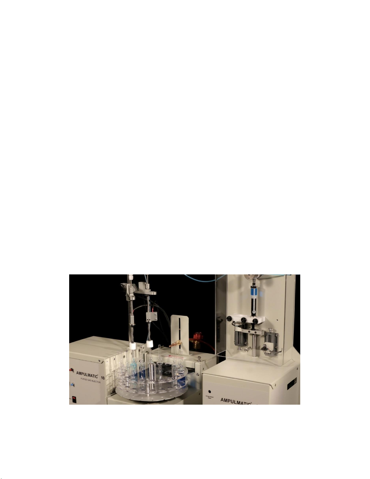
The Bioscience, Inc. Ampulmatic®-10 Liquid Filler accessory is designed to inject a precise
amount of liquid into an ampule in conjunction with the Purge Gas Injector accessory and the
Ampulmatic-10 base unit. The Purge Gas Injector accessory is used to move a plunger head into
each ampule prior to sealing, while the Liquid Filler accessory injects fluid through the plunger
head into each ampule. The Liquid Filler accessory is designed to inject volumes between <1ml
and 20ml into each ampule within the cycle time required to flame seal the ampule.
It was designed with a chemically-inert fluid path to accommodate the injection of a wide range
of chemicals. The Ampulmatic-10 ampule sealer and its accessories were designed to withstand
non-corrosive chemicals commonly found in lab environments. The cases are designed to protect
interior components from chemical leakage or spillage.
The Liquid Filler accessory can be easily added onto any Ampulmatic-10 base unit with the Purge
Gas Injector accessory.
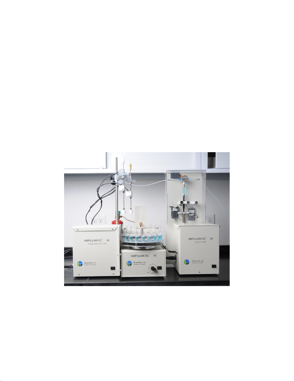
3-1
Ampulmatic-10
Ampule Sealer
Purge Gas Injector
Accessory
Liquid Filler
Accessory
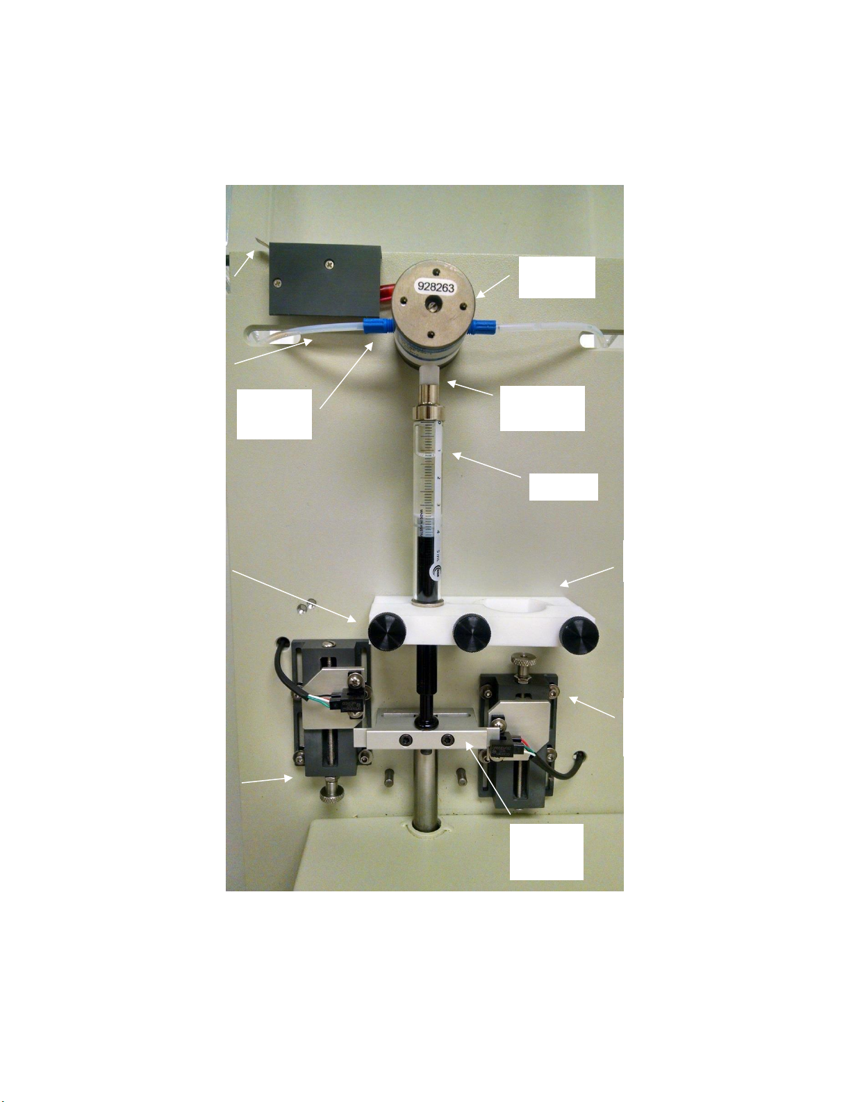
Ampulmatic-10 Liquid Filler Features
3-2
Syringe
Solenoid
Valve
Safety
Switch
Syringe
Clamps
Upper
Limit
Switch
Lower
Limit
Switch
Solenoid
Luer Lock
Black Knob
Fasteners
(3)
Switch
Trigger
Bracket
PTFE
Ferrules
PTFE
Tubing

Unit Specifications
Overall Dimensions
The overall dimensions of the Ampulmatic-10 Liquid Filler accessory are 8”W x 16”H x 8”D (20.3
cm W X 40.6 cm H X 20.3 cm D).
Shipping Weight
The shipping weight of the Ampulmatic-10 Liquid Filler accessory is approximately 27 lbs (12.25
kg).
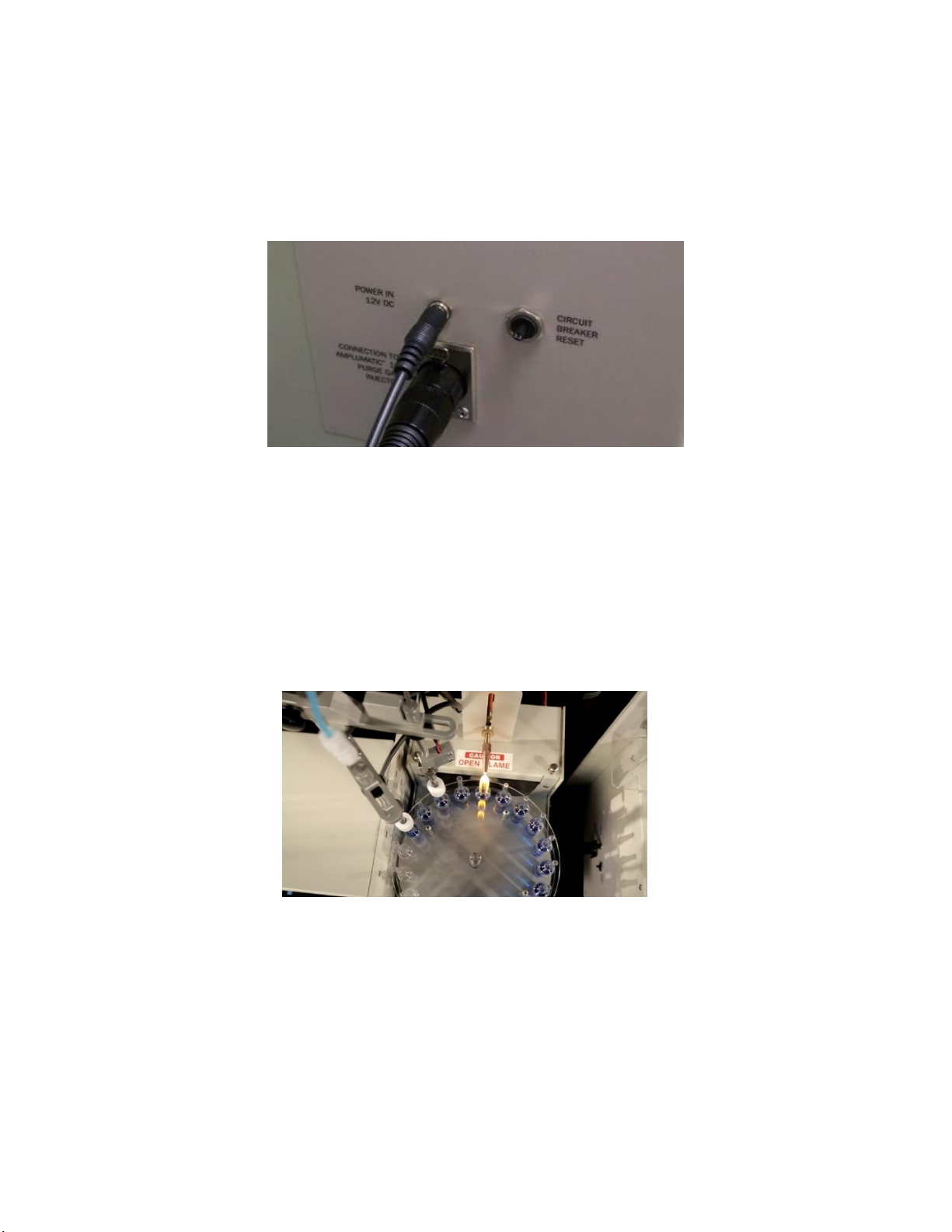
Electrical Requirements
All electrical parts are UL listed/approved. The Ampulmatic-10 Liquid Filler operates internally
on 12 VDC. This voltage can be supplied by the power transformer furnished with your unit from
a power source of from 100 to 240 VAC (50-60 Hz).
Materials of Construction
Outside Body
Powder Coated Aluminum
Fluid Path
Borosilicate Glass, PTFE, 316ss
Note: Corrosive liquids must be tested in advance of filling and sealing for compatibility with the
materials of construction of the Ampulmatic-10 base unit and its accessories. Special materials
for corrosive resistant Ampulmatic-10 models are available by request.
CAUTION: Do not operate the Ampulmatic-10 ampule sealer with corrosive liquids
that are incompatible with the materials of construction of the unit.
Operating Conditions:
Acoustic Noise: <70db(A)
Atmospheric Pressure: 760-1080mBar
Storage Temperature: Between 5°C to 40°C
Operating Temperature: Between 5°C to 40°C
Altitude: Less than 2000m
Humidity Conditions: Between 30% to 90% (non-condensing)
Country of Origin
The Ampulmatic-10 Liquid Filler accessory is manufactured by Bioscience, Inc. in the USA.
4-1

Setup
Follow the instructions for setting up the Ampulmatic-10 base unit (Ampulmatic-10 Operation
and Maintenance Manual) and Purge Gas Injector accessory (Ampulmatic-10 Purge Gas
Accessory Operation and Maintenance Manual). The Purge Gas Injector accessory is required for
the use of the Liquid Filler accessory and must be completely set up before proceeding.
The Ampulmatic-10 ampule sealer and each accessory have separate power supplies. The switch
on the front of the Ampulmatic-10 module controls power to the turntable and ampule rotation.
This power switch does not control power to the purge gas injector accessory nor the liquid filler
accessory.
The switch on the front of the Liquid Filler accessory controls power to the Liquid Filler accessory
only. Do not turn this switch on until the Ampulmatic-10 base unit, Purge Gas Injector accessory,
and Liquid Filler accessory have been completely set up.
After the Ampulmatic-10 has been set up (gas supplies connected and the flame adjustments
made), and the Purge Gas Injector accessory has been completely set up, the Liquid Filler
accessory may be set up.
Reference the “Ampulmatic-10 Liquid Filler Features” located in Section 2-2 of this Manual
during the setup process.
CAUTION: Make sure the power cord is unplugged before opening the case for any
reason!
Note: Use appropriate Personal Protective Equipment (PPE) when operating the
Ampulmatic-10 System. Review the Safety Data Sheets of all chemicals being filling
and/or sealed with this equipment. Recommended PPE includes eye protection and
heat resistant gloves. See the Safety Accessory section of this manual for more
information.
Initial Setup
1. Place the Liquid Filler Injector Head onto the Purge Gas Injector Rod.
If using both a Liquid Filler Injector Head and a Purge Gas Injector Head, the Liquid Filler
Injector Head should be placed on the Rod first, under the Purge Gas Injector Head.
The Injector Heads will be fully aligned later in the setup process.
2. Verify that the Injector Head cables are hooked into the appropriately labeled ports on the
Purge Gas Injector accessory.
5-1

Installing the Liquid Filler Syringe
1. Choose an appropriate syringe size based on the liquid injection volume.
Syringe
Injection Volume
5 ml syringe (270 064)
<1 ml –4 ml
10 ml syringe (270 065)
2 ml –8 ml
25 ml syringe (270 066)
5 ml –20 ml
NOTE: 1ml and 2.5ml syringes may be special ordered for small volume injection.
Please contact Bioscience for more information.
CAUTION: Use syringes provided by Bioscience, Inc. only. Other syringes may not
be designed to fit in the unit.
2. Remove the front and rear white syringe clamps from the Liquid
Filler base plate by unscrewing the black knob fasteners.
3. Attach the syringe to the luer lock on the solenoid valve by twisting
the syringe clockwise onto the luer lock fitting. Do not over
tighten. Orient the syringe so that the flat edge of the metal end
of the syringe barrel is parallel to the base plate and the graduated
syringe readout can be read from the front. If the markings are not
oriented toward front, unscrew the syringe and rotate it counter-
clockwise ¾ turn and retighten.
4. Attach the front and rear syringe clamps to the base plate with the black knob fasteners.
The appropriate orientation of the syringe clamps will depend on whether you are using
the 5 ml, 10 ml, or 25 ml syringe (see next page). Tighten the black knob fasteners so that
the clamps grip the metal end of the syringe barrel. They should turn easily if properly
aligned. Do not force or threads may be damaged.
5-2

Syringe Clamp Positioning
5. Extend the syringe plunger so that it reaches the switch trigger bracket. Insert the provided
#6-32 screw through the bottom of the switch trigger bracket. Straight up and tighten
with an allen wrench to grip the plunger of the syringe.
5-3
5ml Syringe
10ml Syringe
20ml Syringe

Installing the Tubing
For smaller fill volumes, 1/8” outer diameter (OD) tubing is used for 5 and 10 mL syringes (shown
in the pictures below). This is preferred for more rapid startup (washing out previous solution or
solvent, elimination of air bubbles, and easier sealing of connections).
For larger fill volumes, ¼” OD tubing is used to ensure that filling can be done before the sealing
cycle is complete.
1. Attach PTFE tubing to the fitting on the right side of the solenoid valve using PTFE
ferrules. Route the tube through the right-hand slot on the base plate and place the free
end of the tube in the reservoir of fluid that is to be injected.
2. Attach PTFE tubing to the fitting on the left side of the solenoid valve using PTFE ferrules.
Route the tube through the left-hand slot on the base plate.
3. Attach the free end of the tube to the top of the
plunger tube, also using PTFE ferrules.
5-4

Calibrating the Filling Volume
Caution: Potential pinch hazard. Do not put fingers inside the safety shield during
operation.
1. Place an empty container under the Liquid Filler Injector Head to catch any fluid
dispensed during the setup and calibration process.
2. Connect the Liquid Filler accessory power supply. Turn on power to the Liquid Filler
accessory only.
Note: Unplug the connection between the Liquid Filler accessory and the
Purge Gas Injector accessory while calibrating the filling volume. The
solenoid will not engage if the cable is connected while the Purge Gas Injector
power is off. This is a safety feature.
3. Use the “Manually Pump Syringe” button on the Liquid Filler accessory to purge the fluid
path of air. Small air bubbles may remain in the syringe, but this will not affect the injected
volume. However, air bubbles entering the syringe with each stroke may indicate a leak
in the fluid path. If this occurs, consult the Troubleshooting Guide in this Manual.
NOTE: The safety shield must be in the down position for the Liquid Filler
accessory to operate. The unit must be manually restarted every time the
safety shield is raised and lowered. Turn the power switch off and on to
restart.
4. Use the upper and lower limit switch adjustment knobs to adjust the volume of fluid
injected. Note that the plunger in the syringe will not reach the very top of the syringe. Use
the middle of the range of the syringe to inject the amount desired.
For example, to inject 3ml of fluid, the
upper limit switch could be set so that
the plunger reaches a top of 1ml on the
syringe, and the lower limit switch
could be set so that the plunger
reaches a bottom of 4ml on the
syringe, giving a range of 3ml.
5. To check the lower and upper limits of
the syringe, push the “Manually Pump
Syringe” button on the side of the
Liquid Filler accessory. Hold the
button to read the upper limits. Use
the graduated syringe readout on the
front of the syringe to determine the
dispense volume.
6. Dispense fluid into a container to verify the amount dispensed before using in a production
environment. Note: One mL of water weighs one gram.
5-5
Final Setup
1. Connect the Liquid Filler accessory to the appropriate port on the Purge Gas Injector
accessory using the cable provided. The Purge Gas Injector accessory should also be
connected to the Ampulmatic-10 base unit.
2. If using both a Purge Gas Injector Head and a Liquid Filler Injector Head, verify that the
Liquid Filler Injector Head is placed on the Purge Gas Injector Rod first. Position the
Purge Gas Injector Head so that injection occurs at least 2 positions prior to flame sealing.
Position the Liquid Filler Injector Head 1 or 2 positions before the Purge Gas Injector
Head.
3. If using only the Liquid Filler Injector Head, position it so that injection occurs at least 2
positions prior to flame sealing.
NOTE: Refer to the Purge Gas Accessory Operation and Maintenance Manual for
adjustment of plunger heads.
4. Fill the carousel with empty ampules and check for correct operation. Visually inspect
ampules before use to discard any broken or distorted ampules. Defective ampules may
cause improper operation. This unit is designed to accept normal variance in glassware;
however, ampules should be of high quality and uniformity for best results.
5. The Liquid Filler accessory is now set up and ready to use. Turn power on to Ampulmatic-
10 base unit and Purge Gas Injector accessory. Liquid injection will occur automatically.
5-6
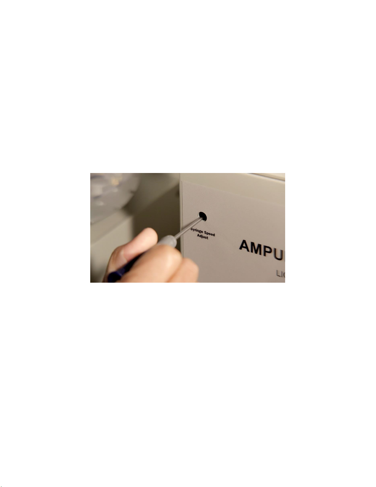
Adjusting the Syringe Speed
The “Syringe Speed Adjust” controls the speed of the syringe as it dispenses liquid. The syringe
must move fast enough to inject the liquid within the time it takes the Ampulmatic-10 base unit to
flame seal an ampule.
If necessary, a small flat-bladed screwdriver can be used to adjust the speed of the syringe by
inserting the screwdriver into the “Syringe Speed Adjust” hole and turning the potentiometer
clockwise to increase the speed or counterclockwise to reduce the speed.
Note: If the speed of the syringe is too fast, air bubbles may form when the syringe is pulled down.
In this case, turn the “Syringe Speed Adjust” counterclockwise to reduce the speed. The dwell
time on the base unit can be adjusted to slow the base unit down if necessary.
5-7

Ampule Glass and Size
The type of glass and size of ampules are important factors to consider in getting the best results
with your sealer. In general, the smaller the ampule and the weaker the glass, the more important
the positioning and adjustment of the filler heads. To get more consistent seals with volatile
substances carefully follow the directions in the main manual. Small ampules (< 2 ml) made of
soft glass (other than borosilicate) will require careful alignment of the accessory filler heads and
possible adjustment of the loading of the integrated filler head spring to avoid ampule breakage.
Soft glass is not recommended due to the rapid heating and cooling during flame sealing; seals
will tend to be brittle and crack easily especially when volatile substances are being sealed.
Standard carousels are designed for Wheaton gold band ampules or equivalent. Ampule samples
or specifications should be provided to Bioscience to confirm compatibility. Custom carousels are
available for non-standard ampule sizes.
6-1

Maintenance
The Ampulmatic-10 Liquid Filler accessory was designed to require a minimum amount of
maintenance. However, following the recommended maintenance procedures and intervals will
ensure that you obtain the highest level of reliability and fluid injection accuracy.
Daily (Before Use)
•Ensure liquid filler plunger head is positioned correctly above ampule for injection.
•Ensure fluid lines and syringe are free of air bubbles during injection.
•Calibrate and check injection volume.
Every 10,000 injection cycles or 25 hours of operation or 1 month, whichever
comes first
•Remove and inspect syringe
•Clean syringe and syringe plunger
•Check syringe and plunger for wear
Every 100,000 injection cycles or 250 hours of operation or 1 year, whichever
comes first
•Replace syringe and/or syringe plunger depending on wear
•Inspect safety shield switch
Every 1,000,000 injection cycles or 2,500 hours of operation or 10 years,
whichever comes first
•Replace relays on electronics board
•Inspect solenoid valve for wear
7-1

Troubleshooting Guide
NOTE: Due to interconnections between the Purge Gas Injector and Liquid Filler
accessories, make sure that the power to the Purge Gas Injector is on (or disconnect
the cable from the Liquid Filler to the Purge Gas Injector) when manually operating
the filler.
Ampulmatic-10 base unit does not advance after connecting Liquid Filler accessory.
OR
Ampulmatic-10 base unit advances, but plunger heads do not go down into ampules.
OR
Ampulmatic-10 base unit advances, plunger heads go down into ampules, but Liquid Filler
accessory does not pump syringe/inject liquid.
•Check to ensure cable is connected between Liquid Filler accessory and Purge Gas Injector
accessory.
•Check to make sure power is connected to Liquid Filler accessory and Liquid Filler
accessory is turned on.
•Check to make sure plunger head for liquid injection is connected to appropriate port on
Purge Gas Injector accessory.
•Check to make sure safety shield is down and safety switch is triggered on Liquid Filler
accessory.
•Check to make sure plunger for liquid injection is dropping down into ampule and that the
ampule detection switch is triggered.
•Ensure upper and lower limit switches are set far enough apart that both are not triggered
simultaneously.
•Adjust “Syringe Speed Adjust” clockwise to ensure that enough force is being applied to
move syringe.
Fluid line contains air bubbles.
•Check to make sure fluid input tube is tightly connected.
•Check to make sure fluid input connector is tightly connected to solenoid valve.
•Check to make sure luer lock is tightly connected to solenoid valve.
•Check to make sure syringe is tightly connected to the luer lock.
•Check to make sure fluid output tube is tightly connected.
•Check to make sure fluid output connector is tightly connected to solenoid valve.
•Check syringe integrity and replace syringe if necessary.
8-1

Inject several drops of water around each connection one at a time. If after several injection cycles
the bubbles disappear that would indicate a connection that is not airtight, the connection might
need to be resealed. If the connection is a threaded connection, try removing and replacing Teflon
tape on the threads.
Syringe clamps do not fit properly around syringe.
•Syringe clamps may need to be reoriented as they have different orientations based on
syringe size.
•Syringe needs to be turned so that flat part of metal barrel end is parallel to base plate.
Syringe pulls in air bubbles on downstroke.
•Adjust “Syringe Speed Adjust” counterclockwise to reduce syringe speed. See “Adjusting
Syringe Speed” in the “Setup” section of this manual.
•Check all fluid path connections for air leaks (see “Fluid line contains air bubbles”)
•Check syringe integrity and replace syringe if necessary.
Syringe does not inject full volume of fluid or travel fully between upper and lower limit
switches.
If syringe does not move quickly enough to complete injection within cycle time of Ampulmatic-
10 base unit, you can:
•Adjust dwell time on Ampulmatic-10 base unit to a longer period (turn the dwell dial
counterclockwise).
•Adjust “Syringe Speed Adjust” clockwise to move syringe faster.
Discoloration of metals and/or painted surfaces of the Liquid Filler.
Stop operation. Check compatibility of all filling solutions with the materials of construction of
the Liquid Filler before continuing. Contact Bioscience, Inc. for information on corrosion-
resistant replacement parts.
8-2

Spare Parts List
Part
PCN
Syringe, 5ml
270 064
Syringe, 10ml
270 065
Syringe, 25ml
270 066
Safety shield switch
270 073
Syringe clamp, rear
270 054
Syringe clamp, front
270 055
Syringe clamp screws
270 056
Solenoid Valve
270 067
Swagelok SS ¼-28 to ¼” OD fitting
270 080
Swagelok SS ¼” OD to 1/8” OD fitting
270 089
Swagelok ¼” OD Teflon ferrules
270 082
Swagelok 1/8” OD SS ferrules
270 081
¼-28 to syringe luer lock fitting, SS
270 077
¼-28 to 1/8” OD fitting
270 094
1/8” Teflon ferrules
270 095
Swagelok 1/8” coupling, SS
210 062
9-1
Other manuals for Ampulmatic-10 Purge Gas Injector
2
Table of contents
Other Bio-Science Laboratory Equipment manuals


Popular Laboratory Equipment manuals by other brands


Izon
Izon AUTOMATIC FRACTION COLLECTOR V1 quick start guide

Scientific Industries
Scientific Industries MULTI VORTEX-GENIE SI-M236 operating instructions

Emperor Aquatics
Emperor Aquatics 02818 instructions

Varian
Varian 3900GC Assembly procedures

ABS
ABS ABT-FRP-04 owner's guide

Hanil
Hanil Ultra 5.0 operating manual