vita V60 i-Line PLUS User manual

VITA V60 i-Line® PLUS
VITA – perfect match.
Instructions for use
VITA Farbkommunikation
VITA shade control
VITA shade reproduction
VITA shade communicationVITA shade determination

2
VITA V60 i-Line® PLUS
Table of Contents
1 Scope of delivery ........................................................................................5
1.1 Contents of the package ...............................................................................5
1.2 Accessories for purchase ...............................................................................5
2 Technical information ....................................................................................5
2.1 General description ...................................................................................5
3 Technical data ..........................................................................................5
3.1 Dimensions/weights ..................................................................................5
4 Electrical data ...........................................................................................6
4.1 Furnace .............................................................................................6
5 Intended use ...........................................................................................6
5.1 Intended purpose and basics of device construction .........................................................6
5.2 Unauthorized modes of operation ........................................................................6
5.3 Authorized modes of operation ..........................................................................6
6 Safety information .......................................................................................7
6.1 Pictograms ..........................................................................................7
6.2 Ambient conditions ...................................................................................7
6.3 Safety functions ......................................................................................7
7 Setup and connections ...................................................................................8
7.1 Installation location ...................................................................................8
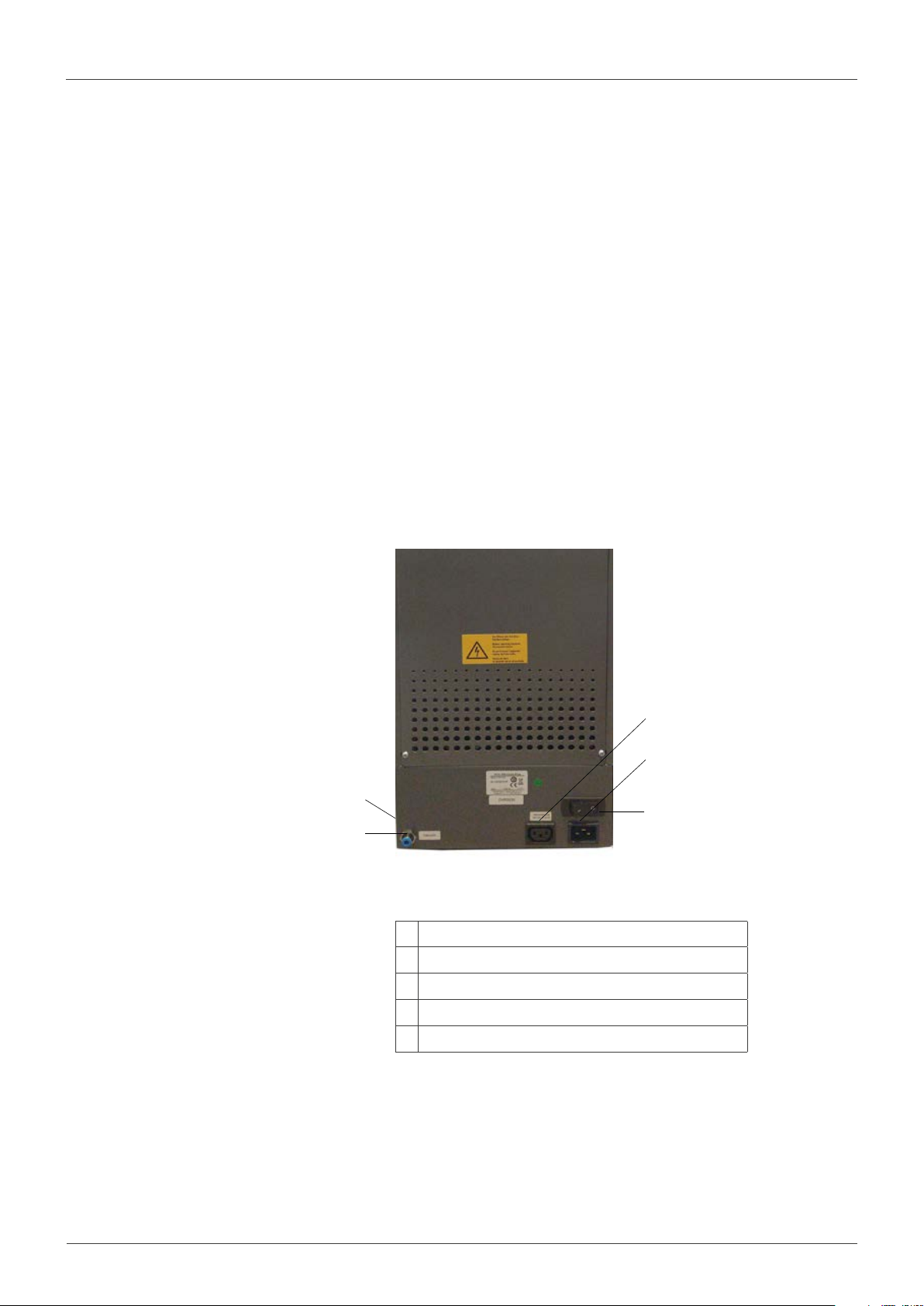
7.2 Device connections ...................................................................................8
8 Startup ................................................................................................9
8.1 Switching off the device, decommissioning ................................................................9
9 Cleaning the furnace ....................................................................................10
9.1 Cleaning the touchscreen .............................................................................10
9.2 Cleaning firing for the firing chamber ....................................................................10
9.3 Firing chamber insulation ............................................................................ 10
10 CE mark ..............................................................................................11
11 Mains power supply failure ...............................................................................11
12 Warranty and liability ....................................................................................12
12.1 Spare parts ........................................................................................12
13 Operating the touchscreen ...............................................................................12

3
VITA V60 i-Line® PLUS
14 Switching the device on ..................................................................................13
14.1 Start/change to standby .............................................................................13
15 Operation and functions .................................................................................14
16 Keyboard functions .....................................................................................15
17 Select/start firing programs ...............................................................................16
18 Changing program values ................................................................................17
18.1 Pre-drying .........................................................................................18
18.2 Temperature rise and temperature holding time ...........................................................19
18.3 Cooling ...........................................................................................20
18.4 Vacuum setting ....................................................................................21
18.5 Saving program values ...............................................................................22
18.6 Rapid cooling ......................................................................................22
18.7 Program backup ....................................................................................23
18.8 Administration of firing programs ......................................................................23
19 Device settings .........................................................................................25
19.1 Device information ..................................................................................26
19.2 Factory settings ....................................................................................26
19.3 Temperature setting and cleaning firing .................................................................27
19.4 Temperature display °C or °F ..........................................................................28
19.5 Language .........................................................................................28
19.6 Entering PIN for device settings .......................................................................28
19.7 Entering PIN for firing programs .......................................................................29
19.8 Blocking firing programs .............................................................................29
19.9 Loudspeaker tone duration ...........................................................................30
19.10 Date/time settings .................................................................................30
19.11 Setting the standby temperature ......................................................................31
20 Software update ........................................................................................31
21 Error messages .........................................................................................32
22 Alphabetical table of contents .............................................................................33
23 List of figures ..........................................................................................34
24 List of tables ...........................................................................................35

4
VITA V60 i-Line® PLUS
Dear Customer,
Congratulations on your purchase of the VITA V60 i-Line PLUS. This device is a modern firing furnace for the dental industry.
As a quality manufacturer of dental ceramic materials and devices, VITA Zahnfabrik ensures that only high-quality materials were
used in the development and manufacture of the VITA V60 i-Line PLUS. Our experience based on over 30 years of ceramic furnace
development is reflected in this product. We hope you enjoy many years of working with the VITA V60 i-Line PLUS.
This device has been designed in accordance with the latest technological benchmarks and complies with all international safety
standards. However, hazards may occur with improper handling. Please read these instructions for use and observe the instructions.
Reading and understanding this operating manual will help you maintain safety, reduce expenses as a result of repairs and downtime
and increase the reliability and service life of the device. All of the illustrations and drawings in this operating manual are intended for
general explanatory purposes and are not authoritative for the detailed construction of the device.
The operating manual must always be kept close to the device. It must be read and followed by all persons responsible for performing
tasks such as operation, troubleshooting during operation and cleaning and servicing (maintenance, inspection, repairs), either with or
on the device.
We hope that you will find using the VITA V60 i-Line PLUS to be an enjoyable and successful experience.
Copyright
These operating instructions must be treated as confidential. They should only be used by authorized persons.
They may only be transmitted to third parties with the written consent of VITA Zahnfabrik H. Rauter GmbH & Co. KG.
All documentation is protected by copyright. The transmission and reproduction of documents,
even excerpts, and the use and communication of their content are not permitted without express written authority.
Violations are an offense and liable to compensation.
We reserve all rights to exercise intellectual property rights.
These notes warn of hazardous situations with the risk of personal injury or damage to the device.
These notes point to useful advice, explanations and supplements.
Table 1 – Explanation of notes and information
Note:
Information:

5
VITA V60 i-Line® PLUS
1 Scope of delivery
1.1 Contents of the package
Complete with
• 1 VITA V60 i-Line furnace
• 1 Firing platform
• 1 Cable for mains power connection
• 1 Operating Manual
• 1 Connection cable for the vacuum pump
• 1 Vacuum hose
• 2 Firing object storage trays at the side
1.2 Accessories for purchase
• Vacuum pump: 230/240 volt, 50/60Hz, 115 volt, 50/60 Hz
or 100 volt, 50/60 Hz.
• 2 Firing object storage trays at the side
2 Technical information
2.1 General description
• High temperature accuracy (+/– 2°C)
for optimal firing results
• Time-saving, user-friendly, small footprint
• 2 Firing object storage trays at the side
• Firing chamber equipped with high-quality insulation material
• Quartz firing muffle
• Temperature sensor (platinum/rhodium-platinum)
3 Technical data
3.1 Dimensions/weights
• Width: 260 mm
• Depth: 420 mm
• Height: 570 mm
• Weight: 18 kg
• Firing chamber inner diameter: 90 mm, height: 55 mm
• Firing chamber temperature: max. 1200°C

6
VITA V60 i-Line® PLUS
4 Electrical data
4.1 Furnace
• Electrical connection: 230 volt, 50/60 Hz
or 110 volt, 50/60 Hz
• Power consumption: max. 1500 watt
5 Intended use
5.1 Intended purpose and basics of device construction
The VITA V60 i-Line PLUS is a fully automatic and microprocessor-controlled
firing unit for all dental ceramic firing processes.
5.2 Unauthorized modes of operation
The operation of the device with power sources, products, etc., which are
subject to hazardous materials regulations, using equipment modified by the
user, or operation that could have any negative impact on the health of the
operating personnel is not permitted.
5.3 Authorized modes of operation
The operation of the device is only permitted if this operating manual
has been completely read and understood and the procedures described
in it have been observed. Any other or additional use, e.g., processing
of products other than those intended, as well as handling of hazardous
materials or substances injurious to health, is considered to be contrary to
the recommended use. The manufacturer/supplier will not be liable for any
damage resulting from such unauthorized use.
The risk of such use is borne exclusively by the user.
Table 2 – Overview of pictograms
This pictogram warns the user about hazardous voltage.
Before opening the instrument, always disconnect it from the mains current by unplugging the
power plug.
Dispose of electrical and electronic equipment separately, not with household waste.
The black bar under the "wheeled bin" symbol indicates that the device was placed on the market
after August 13, 2005. Please note that the device is subject to European Community Directive
2012/19/EC (WEEE) and the national laws valid in your country, and it must be disposed of
accordingly. Contact your dealer, if you need to dispose of the device.
This pictogram warns the user about hot surfaces Burns are possible.
9.2 Hazardous voltage
Separate disposal
Hot surface

7
VITA V60 i-Line® PLUS
6 Safety information
6.1 Pictograms
The manufacturer is not liable for accidents to the user occurring
when the device is open!
Never operate the device without the firing base installed.
In continuous operation (max. final temperature, max. firing time),
some parts of the firing chamber may reach high temperatures (above 70°C).
Do not reach into the open firing chamber when the device is switched on.
There is a risk of electric shock or burns from touching live or hot parts.
6.2 Ambient conditions
• Use indoors
• Ambient temperature –10°C to 40°C
• Relative humidity 80% at 40°C
• Max. altitude 3800 m above sea level. NN
• Fluctuations in nominal voltage are not greater than plus 10% and
minus 15% of the nominal voltage.
6.3 Safety functions
The furnace has the following safety and monitoring features:
• Temperature sensor monitoring
• Vacuum monitoring
• Power failure protection
• Obstruction sensor
• In the event of danger or emergencies, the device can be switched off
immediately using the mains switch

8
VITA V60 i-Line® PLUS
1
2
3
4
5
7 Setup and connections
7.1 Installation location
• Install the device in a dry, heated room.
The distance to the closest wall should be at least 25 cm
(see also Section 6.2, Ambient conditions).
• When the temperature is below 15°C (e.g., after transport), leave the
device to stand for approx. 30 minutes at room temperature before using it
for the first time.
• Ensure that the surface where the device is installed is heat resistant.
The emissions and heat radiation of the device are within a non-hazardous
range. However, heat-sensitive surfaces on furniture and veneers could
become somewhat discolored over time due to the constant eects of heat.
• Prevent direct sunlight from coming into contact with the device.
• Do not place any flammable objects in the vicinity of the device.
• Do not set up the device in such a way that makes it dicult to press the
main switch and pull out the power supply cord.
7.2 Device connections
* The identification plates show information about the fuses
used in the device.
Fuses with other ratings must not be used.
230 volt model: T 8 H 250 V
110 volt model: T 15 H 250 V
Figure 1 – Device connections
Table 3 – Device connections
1 USB ports on the side
2 Vacuum tube connection
3 Connection for vacuum pump
4 Mains power supply connection
5Main switch

9
VITA V60 i-Line® PLUS
Figure 1 – Device connections
Table 3 – Device connections
8 First commissioning
Before the first use, please read the Safety Information in Section 6!
For information about the device connections, refer to Section 7.2
• Connect vacuum pump with electrical connection and tubing connection to
the device.
• Connect the device to the mains power supply using the mains power cable
supplied.
Important! Avoid electrical multiway socket outlets with
extensions, as there is a risk of fire with overload.
• Switch on the device at the main switch. The lift moves to the lower position.
• Clean or wipe the lift plate and the lift plate gasket (dust particles from the
insulation are deposited during transportation of the device).
• Attach the firing base to the lift plate.
Important! Never operate the device without the firing base
installed.
8.1 Switching o the device, decommissioning
When the device is not in operation, move the lift into the firing chamber and
switch the device o at the main switch. Closing the firing chamber protects
the insulation and prevents moisture absorption.

10
VITA V60 i-Line® PLUS
9 Cleaning the furnace
Important! Before each cleaning operation, remove the power
supply plug!
It is not necessary to clean the inside of the firing chamber.
Cleaning the casing of the firing chamber at regular intervals with a damp
cloth contributes to its operating safety.
Important! In all cleaning work, you must never use any
detergents or flammable liquids.
9.1 Cleaning the touchscreen
Dirt on the display caused by impact, as well as fingerprints can be removed
with a microfiber cloth. Cleaning should be performed with the device
switched o in order to exclude unintended resetting of functions in the
display.
9.2 Cleaning firing for the firing chamber
It is recommended to conduct a cleaning firing process regularly,
e.g., every 100 operating hours, see 19.3.
9.3 Firing chamber insulation
The firing chamber contains ceramic mineral fibers as insulation material
(Index No. 650-017-00-08), which is classified as a CAT 2 carcinogen
(Annex VI, EC 1272/2008). When working with the firing chamber or
exchanging the firing mue, fiber dust may be discharged. Dust may be
carcinogenic if inhaled, irritating the skin, eyes and respiratory system.
When exchanging the firing mue, please proceed as follows:
• Wear long-sleeved protective clothing
• Wear safety goggles, as well as protective gloves
• Use a dust vacuum system or wear a FFP 2 respirator.
Once work has been completed, rinse dust from unprotected skin using cold
water. Wash workwear separately from everyday clothing.

11
VITA V60 i-Line® PLUS
10 CE mark
With the CE mark, a legally binding declaration is made that the device
meets the essential requirements of Directive 2006/42/EC (on machines),
Directive 2011/65/EU (RoHS) as well as Directive 2014/30/EU (EMC).
11 Mains power supply failure
The instrument is equipped with power supply failure protection. This
component prevents a program stop and any incorrect firing in the event
of a brief failure of the mains power supply. The power failure protection is
activated as soon as the mains power supply fails when a firing program is
running.
Mains voltage failure time less than 80°C
The program continues to run after re-establishment of the mains power
supply and is not interrupted. The display is out of order during this period.
Once the mains power is supplied again, the running program reappears in
the display.
Mains voltage failure time greater than approx. 80°C
Program is stopped. Display is out of order. After the mains power supply
has been established, an alarm tone sounds and the display shows that the
firing cannot continue.
Once the mains power is supplied again, the time required for
switching back on is approx. 30 sec.

12
VITA V60 i-Line® PLUS
12 Warranty and liability
The warranty and liability are based on the terms and conditions stipulated in
the contract. In the event of software modifications without the knowledge
and approval of VITA Zahnfabrik H. Rauter GmbH & Co. KG, all liability and
warranty claims are invalidated.
12.1 Spare parts
Spare parts must comply with the technical requirements specified by the
manufacturer. This is always ensured when using original VITA spare parts.
Further information on this device is available on our homepage:
http://www.vita-zahnfabrik.com
Software updates are available as downloads under Produkte/
Brandführung/Brennofen/VITA V60 i-Line PLUS. A registration
option is also provided via Service/VITA Update-Messenger so that
the latest information on the device is automatically emailed to you.
In case of technical queries regarding the device, as well as repair and
warranty provisions, you may contact us at:
Email: instruments@vita-zahnfabrik.com
Phone +49 (0) 7761/562 -105, -106, -114
13 Touchscreen operation
The touchscreen is operated using the touch-sensitive surface of the screen.
In order to activate a function, the corresponding button must be pressed.
Pressing a button lightly with your finger will first cause the button to change
color (the button is outlined in orange). Lifting your finger from the button
then activates the selected function.
Press the button lightly with your finger. The action will be
performed when you lift your finger. Pressing too heavily or
operating with sharp-edged or hot objects causes damage to the
touchscreen

13
VITA V60 i-Line® PLUS
1 2 3 14.1 Starting/switching to standby
Press the Standby button. The lift moves into the firing chamber, and the
firing chamber heats up to the set standby temperature. After reaching the
standby temperature and holding it for five minutes, the device is ready for
firing processes. The first time standby is started after switching on the firing
device, the firing chamber remains slightly open for five minutes in order to
remove moisture from the firing chamber (VITA AntiCon).
The Standby button has two temperature values. You can choose between
Normal Mode (adjustable standby temperature, e.g. 500°C) and Saving Mode
(fixed value, 200°C) (VITA Energy Efficiency).
Temperature changes in Normal Mode can be made via Device Settings/
Standby Temperature (see Section 19.11). The switch between Normal and
Saving Mode is done by pressing the button again during active Standby.
Active mode is displayed in orange.
Standby is terminated by pressing the green START or red STOP button,
the program name button or the program number button.
Figure 3 – Last used firing program
Figure 4 – Starting/switching to standby
Table 4 – Starting/switching to standby
Figure 2 – Start screen
14 Switching the device on
Switch the device on with the main switch (on the back of the device).
After switching on, the display briefly lights up blue. Then a reference run
and a self test are carried out.
After another 10 sec., the last used firing program is displayed.
1 Standby button
2STOP button
3START button

14
VITA V60 i-Line® PLUS
4 2 3
5
6
7
8
1
17
914 10 15 11 16 12 13
15 Operation and functions
Program overview
No.
1
2
3
4
5
6
7
8
9
10
11
12
13
14
15
16
17
Designation
Program backup
Program number
Programs
Temperature display
Pre-drying
1. Temperature rise/holding time
2. Temperature rise/holding time
Cooling
Lift positions
Standby
Device settings
Rapid cooling
STOP button
Button for lift
Vacuum
Save button
START button
Function
Lock open, program open - lock closed, program backed up
Entry field for program number 1 – 200
Entry/change of program name, program list
Displays current combustion chamber temperature
Pre-drying program area
Program area for first temperature rise and first temperature holding time
Program area for second temperature rise and second temperature holding time
Program area for cooling to lower temperature with holding time
Displays number of lift positions for pre-drying
Heating to standby temperature (Normal and Saving Modes)
Setting/display of language, operating hours, etc.
Rapid cooling of combustion chamber temperature to standby temperature
Stop program
Manual control of the lift
Program area for vacuum settings
Save changes
Start program
Note
18.7
17
18.8
18.1
18.2
18.2
18.3
14.1
19
18.6
17
18.4
18
Program areas
Table 5 – Overview of operation and functions
Figure 5 – Overview of operation and functions

15
VITA V60 i-Line® PLUS
2
8
3
5
4
7
16 Keyboard functions
When you touch a program area in the program overview, the associated
editing window with keyboard appears. The values of the program area can
be changed in the editing window.
1 6
Figure 6 – Example of editing field for vacuum
Table 6 – Editing field for vacuum
1Button for deactivating/activating the function
2 Display field for the program areas (see Section 17)
3 Buttons 0-9 – Entry for program values
4 Delete last digit of the entry in the display field
5 Delete value in the display field
6 Back to program overview without accepting change
7 Back to program overview with accepting change, without saving
8 Select next entry field
9 Direct selection of time/temperature

16
VITA V60 i-Line® PLUS
4
5
6
7
1
2
3
17 Select/start firing programs
Firing programs for VITA ceramic materials are already preprogrammed in the
VITA V60 i-Line PLUS. These correspond to the recommended VITA settings.
A firing program is selected by entering the number. The preset assignment of
the program numbers can be viewed via the program name (see Section 18.8
Changing the program name). The program is selected by briefly pressing on
the program number or the material and program name.
1 Press the program number button
2 Enter the program number (1 –200)
3 Confirm the selected firing program
4Selected program is displayed
5 Start program with START button
6 Program sequence is shown in color
7 Program stop with STOP button
Figure 7 – Pressing the program number button
Figure 8 – Entering the program number
Figure 9 – Starting the program
Figure 10 – Program stop Table 7 – Selecting the firing program

17
VITA V60 i-Line® PLUS
1 2 3 4
5 6 7
18 Changing program values
To change the program values, touch the specific program area in which the
values are to be changed. The associated editing window opens and program
changes can be made.
Program values displayed in white are saved values.
Program values displayed in orange are valid for a program run until the
program changes. After reselecting the program, the last saved values are
displayed again.
The program values displayed in red can be permanently backed up
with the Save button if no program backup (lock open) has been set
(see Section 18.7). The program is then open for changes and the Save button
is actively displayed (see Section 18.5).
One-time changes are possible during active program backup (lock closed).
However, the changes can only be saved by entering the PIN in the displayed
keyboard after pressing the Save button (see Section 19.8).
1 Pre-drying (see Section 18.1)
2 First temperature rise/holding time
(see Section 18.2)
3 Second temperature rise/holding time
(see Section 18.2)
4 Cooling (see Section 18.3)
5Display of the current lift position
(see Section 18.1)
6 Vacuum settings (see Section 18.4)
7 Save button (see Section 18.5)
Figure 11 – Changing program values
Table 8 – Changing program values

18
VITA V60 i-Line® PLUS
9
8
7
6
5
1 4 2 10 3
18.1 Pre-drying
Times for the individual pre-drying positions
The possible holding times of the individual lift positions depend on the
preselected pre-drying time. Therefore set the pre-drying time first and then
enter the time at the middle and lower lift position.
The time for the upper lift position is automatically calculated.
If the pre-drying time is extended, the time change is assigned to the
upper lift position. The lower and middle positions remain the same.
If the pre-drying time is shortened, the holding time is shortened for the
upper lift position. The lower and middle positions remain the same.
If the selected pre-drying time is less than the total time of the individual
lift holding times, one-third of this time is assigned to each of the individual
lift positions.
The lift positions (in %) remain the same with a change in holding times
and can be freely altered. The factory setting for lift position one is 0%,
lift position two is 15% and lift position three is 30%.
Altered program values are displayed as orange in the program overview and
can be used for one program sequence or are permanently saved with the
Save button in the program overview (see Section 18.5).
When the pre-drying temperature changes, the switch-on
temperature of the vacuum pump changes. If the pre-drying time
changes, the holding times of the lift positions change.
1 Selected program area, here: pre-drying, is actively displayed
2 Display field for the pre-drying time lights up in light blue and is active.
Enter time value using the keyboard. Value entry: 0:00 – 40:00 min/sec.
3Display field for pre-drying temperature - enter temperature using keyboard.
Value entry: 200°C – 800°C.
4Deactivate/activate pre-drying
5 Symbols show the lift positions
6 Time setting for lower lift position
7 Time setting for middle lift position
8 Time setting for upper lift position (is automatically calculated)
9Lift position settings
10 All program areas can be selected and processed in this mode.
Figure 12 – Pre-drying program area Table 9 – Pre-drying

19
VITA V60 i-Line® PLUS
173
2
6
5
4
18.2 Temperature rise and temperature holding time
The device has two program areas for temperature rise and temperature
holding time.
The second temperature rise and the second temperature holding time can
each be activated and deactivated. Both areas are operated in the same
manner. Activate first or second program area.
The display shows:
Setting values for final temperature: Minimum and maximum values
are dependent on the activated program areas. When changing the final
temperature, the heating rate (°C/min) is maintained and the rise time
in min/sec. is adjusted.
Attention: The run time of the vacuum pump is adjusted to the rise
time.
Setting values for the rise time: Minimum and maximum values are
dependent on the activated program areas.
When changing the rise time, the heating rate in °C/min is adjusted.
Attention: The run time of the vacuum pump is adjusted to the rise
time. The pump is switched off after the final temperature is reached.
Setting values for heating rate: Minimum and maximum values are
dependent on the activated program areas. When changing the heating rate
°C/min, the rise time is adjusted.
Attention: The run time of the vacuum pump is adjusted to the rise
time. The pump is switched off after the final temperature is reached.
Only those values can be set which are displayed via the entry field.
Altered program values are displayed in orange in the program overview and
can be used for one program sequence or permanently backed up with the
Save button in the program overview (see Section 18.5).
When changing the rise time, heating rate or final temperature,
the values for switching on the vacuum pump are adjusted
(see Section 18.4).
1Ascending phase
2Holding phase
3 Entry of the duration of the ascending phase
4 Entry of the temperature gradients
5 Entry of the duration of the holding phase
6 Entry of the temperature in the holding phase
7 Activation of the ascending and holding phase
Figure 13 – Temperature rise and
temperature holding time
Table 10 – Ascending phase and holding phase

20
VITA V60 i-Line® PLUS
421
3
5
18.3 Cooling
The maximum value is dependent on the final holding temperature.
The cooling temperature must be lower than the final holding temperature.
Only those values can be set which are displayed via the entry field.
Altered program values are displayed in orange in the program overview and
can be used for one program sequence, or permanently backed up with the
Save button in the program overview (see Section 18.5).
1Deactivate/activate cooling phase
2 Set the temperature holding time
3 Set the cooling temperature
4Cooling phase
5 Set lift position for cooling
Figure 14 – Cooling phase Table 11 – Cooling phase
Table of contents
Other vita Laboratory Equipment manuals
Popular Laboratory Equipment manuals by other brands

Markes International
Markes International HiSorb Agitator U-HSAG-20 Instructions for use

Azure Biosystems
Azure Biosystems Cielo AIQ030 user manual

GE
GE 800 user manual

PolyScience
PolyScience MX07R-20 Operator's manual

Consort
Consort EVS1000 Series manual

Millipore Sigma
Millipore Sigma SNAP i.d. 2.0 user guide