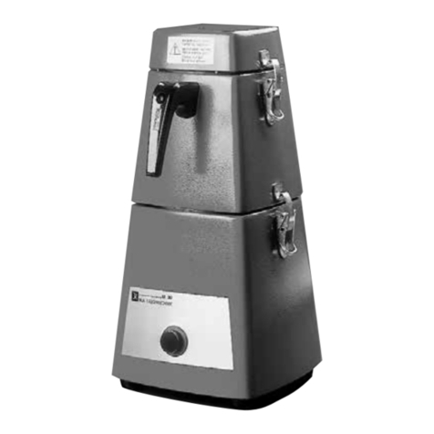
IKA ULTRA-TURRAZ UTL 1000/10 User manual

IKA
WERKE
Reg. No. 4343-01
IKA
U L T R A - T U R R A X
UTL 1000/10
Serial No.: 06-5819
OPERATING INSTRUCTIONS EN

IKA
®
-WERKE
2

IKA
®
-WERKE
1
Table of Contents
1 For your safety..................................................................................................4
1.1 General dangers .............................................................................................4
1.2 Definition.........................................................................................................4
1.3 Use as directed...............................................................................................4
1.4 Protective measures .......................................................................................5
1.4.1 Safety obligations on the part of the operator..........................................5
1.4.2 Specific safety information and symbols used.........................................6
1.4.3 General safety information ......................................................................7
1.4.4 Basic safety information during normal operation....................................8
1.4.5 Basic safety measures for maintenance and repairs...............................9
1.4.6 Working on electrical equipment ...........................................................11
1.4.7 Working on the barrier system...............................................................12
1.4.8 Observing environmental protection guidelines .....................................13
1.5 Remaining dangers.......................................................................................13
2 Description......................................................................................................14
2.1 Construction of the ULTRA-TURRAX
.........................................................15
2.1.1 Sealing cartridge....................................................................................15
2.1.2 Mixing tools............................................................................................15
2.1.3 Drive ......................................................................................................15
2.1.4 Frame ....................................................................................................15
3 Specification sheet.........................................................................................16
3.1 Dimensions and weight:................................................................................18
4 Installation ......................................................................................................19
4.1 Securing the machine ...................................................................................19
4.2 Connecting product lines ..............................................................................19
4.3 Power supply ................................................................................................23
5 Operating mechanisms on the machine ......................................................24
6 Placing the ULTRA-TURRAX
in operation..................................................24
6.1 Connecting the machine ...............................................................................24
6.2 Short test ......................................................................................................24

IKA
®
-WERKE
2
6.3 Information for working with product .............................................................25
6.3.1 Periphery ...............................................................................................25
6.3.2 Possible adjustments of the ULTRA-TURRAXfor a process .............25
6.3.3 Starting the machine..............................................................................25
6.3.4 Adjusting the output quantity .................................................................26
7 Servicing .........................................................................................................27
7.1 The mechanical seal.....................................................................................27
7.2 The mixing tool .............................................................................................28
8 Assembly and disassembly...........................................................................29
8.1 Tools for assembly........................................................................................29
8.2 Mixing tool.....................................................................................................30
8.2.1 Removing the mixing tool ......................................................................30
8.2.2 Assembly of the mixing tool ...................................................................30
8.3 Mechanical seal cartridge .............................................................................31
8.3.1 Disassembly of the mechanical seal cartridge.......................................31
8.3.2 Assembly of the mechanical seal cartridge ...........................................31
8.4 Motor shaft....................................................................................................32
8.4.1 Removing the motor shaft .....................................................................32
8.4.2 Assembly of the motor shaft ..................................................................32
9 Ordering spare parts......................................................................................33
10 Parts list ULTRA-TURRAX
UTL 1000/10 .....................................................35
11 Seal materials and alternative.......................................................................37
12 Assembly drawing..........................................................................................38
12.1 Detail 1 of assembly drawing ....................................................................39
12.2 Detail 2 of assembly drawing ....................................................................40
13 Dimension sheet.............................................................................................41
14 Troubles/Causes and troubleshooting.........................................................42
15 EC Declaration of Conformity........................................................................45
16 IKA address overview ....................................................................................46
Annexe:
• Documentation shrink disc TLK 603

IKA
®
-WERKE
3

IKA
®
-WERKE
4
1 For your safety
1.1 General dangers
The machine itself is not dangerous if directions for its use are followed. However, if
this machine is modified or combined with other machines dangers may arise that
could not be foreseen by the manufacturer. We must point out that the user must
follow the guidelines for the given workplace when using this machine.
1.2 Definition
The terms used in the operator’s manual correspond to EN ISO 12100-1 / 2.
The internal technical documentation also corresponds to EN ISO 12100-1 / 2.
1.3 Use as directed
To prevent injury to personnel and damage to the machine, the machine is only to be
operated as directed.
The machine is designed for the production of mixtures in a fluid phase. The mix-
tures produced are emulsions (fluid/fluid) and suspensions (fluid/solid).
The machine is also suited for homogenization as well as for producing colloidal so-
lutions with viscosities up to approx. 50 Pas.
To protect against damage from foreign objects, such as, screws, stones, pieces of
wood etc. to the mixing tools, it is recommended that appropriate measures be taken
to prevent such objects from entering the machine.

IKA
®
-WERKE
5
1.4 Protective measures
1.4.1 Safety obligations on the part of the operator
The machine (including the subassemblies) has been designed and built in accor-
dance with a tolerance analysis and careful selection of the harmonized standards to
be observed as well as other technical specifications. It thus corresponds to the state
of the art and provides maximum safety during operation.
The machine's safety can however only be guaranteed in practice if all of the meas-
ures required are fulfilled. The machine operator is obliged to plan these measures
and control implementation thereof.
In particular, the operator must ensure that:
• the machine is only used for its intended purpose,
• the machine is only operated when it is in a perfect and functional condition, and
the functions of the safety equipment in particular are examined regularly,
• the necessary personal protection equipment for operating, maintenance and re-
pair personnel is available and worn,
• the operating instructions are always legible and available in full wherever the
machine is used,
• the machine is only operated, maintained and repaired by appropriately qualified
and authorized personnel,
• this personnel receives regular instruction regarding all of the relevant issues
governing work safety and environmental protection, as well as being familiar with
the operating instructions and the safety information contained herein in particular
• all safety and warning information attached to the machine remain in place and
are legible.

IKA
®
-WERKE
6
1.4.2 Specific safety information and symbols used
The following operating instructions contain specific safety information referring to
the unavoidable remaining risks when operating and maintaining the machine. These
risks involve dangers for
• persons
• the product and machine
• the environment.
The symbols used in the operating instructions are primarily intended to draw atten-
tion to the safety information.
Danger
This symbol indicates dangers relating to persons in
particular (hazardous, danger of injury).
Caution
This symbol indicates dangers relating to the machine,
material and environment in particular.
The most important objective of safety information is to prevent danger to persons.
If safety information is preceded by a warning triangle marked "Danger", this does
not necessarily eliminate dangers for the machine, material and environment.
If safety information is preceded by a warning triangle marked "Caution”, it can be
assumed that there is no danger for persons.
The symbol used can not replace the text in the safety information. Therefore, the
text should always be read in full.
Info
This symbol does not refer to safety information, but
rather information for improved understanding of ma-
chine processes.

IKA
®
-WERKE
7
1.4.3 General safety information
Danger
Modifications to the system and its components are only
permitted upon obtaining written authorisation from IKA.
Otherwise, the warranty and declaration of conformity
will become null and void.
Danger
When connected to the power supply, the system is live.
This voltage can have fatal consequences if contacted.
Info
Subject to technical modifications.

IKA
®
-WERKE
8
1.4.4 Basic safety information during normal operation
Danger
Before switching on the machine, obtain information on
how to behave in the event of abnormal occurrences.
Danger
The machine may only be operated by appropriately
trained and authorised persons familiar with the operat-
ing instructions (and those for the subassemblies) and
capable of working according to them.
Danger
At working chamber temperatures exceeding 65°C, there
is a danger of burning at the container and supply pipes.
In this case, the operator must apply protection against
accidental contact with hot components.
Caution
The machine may not run dry!
The mechanical seal must always be surrounded by
liquid.
Info
The machine is not suitable for adding and processing
purely dry substances. This can result in serious dam-
age to the device.
Info
When changing the dispersion material, check whether
the materials of the axial-face seal and O-ring are still
suitable. It may be necessary to replace these compo-
nents with other materials. If in doubt, contact the sup-
plier.
Info
Following all assembly work, free movement of the drive
shaft must be ensured by manual turning before switch-
ing on the drive. Secure the drive against unauthorised
activation.

IKA
®
-WERKE
9
1.4.5 Basic safety measures for maintenance and repairs
Danger
The machine may only be maintained by qualified and
authorised personnel under observation of the safety
information and who are familiar with the operating in-
structions (and those for the subassemblies) and are
capable of working according to them.
Danger
Switch off the power supply at the main switch prior to
maintenance or repair work and secure with a padlock.
The key to this lock must be held by the person conduct-
ing the maintenance or repair work.
Danger
When replacing heavy machine components, use suit-
able and functional load suspension devices and stop
materials only.
Danger
Prior to maintenance or repair work, ensure that all parts
of the machine which may need to be contacted have
cooled down to ambient temperature.
Danger
Prior to maintenance or repair work, block access to the
machine work area for unauthorised persons. Attach in-
formation sign indicating maintenance or repair work.
Danger
Observe inspection and maintenance intervals stipulated
in the operating instructions. Observe maintenance and
repair instructions for subassemblies contained in these
operating instructions.
Danger
When working at the shrink disc consider the installa-
tion manual of the sub-supplier at the end of this man-
ual.

IKA
®
-WERKE
10
Danger
Dispose of environmentally hazardous lubricating, cool-
ing or cleaning agents appropriately.
Info
Following all assembly work, free movement of the drive
shaft must be ensured by manual turning before switch-
ing on the drive. Secure the drive against unauthorised
activation.
Info
Great care should be exercised when working on the
sealing cartridge. The axial-face seals are made from a
very brittle material and are therefore very sensitive to
any kind of impact which should be avoided.

IKA
®
-WERKE
11
1.4.6 Working on electrical equipment
Info
Check whether the motor is running in the correct direc-
tion (arrow on the ventilator unit) by switching it on and
off briefly.
Info
The device connection must comply with VDE stan-
dards. Ensure that the motor voltage for the motor con-
nection and the mains voltage are identical. The motor
voltage is indicated on the motor rating plate or in the
technical data sheet.
Danger
• Repair work on the machine's electrical equipment
may only be carried out by qualified electricians.
• Check electrical equipment on a regular basis.
• Secure loose connections.
• Replace damaged lines/cables immediately.
• Always keep the switching cabinet closed. Access is
only permitted to authorised personnel with the ap-
propriate keys/tools.
• Never clean switching cabinets or other electrical
equipment enclosures by spraying with a water pipe.

IKA
®
-WERKE
12
1.4.7 Working on the barrier system
Note
The machine may not be operated (not even for short
periods) without an intact barrier system. Otherwise the
mechanical seal may be destroyed.
Danger
Maintenance and repair work on the barrier system may
only be carried out by personnel specially trained for
this purpose.
Before starting the maintenance and repair work, let the
barrier system cool down and depressurise it!
Replace the hose lines at regular intervals as a preven-
tive maintenance measure, even if no damages can be
detected!
(Observe the manufacturers' indications!)
Danger
Before starting the system after maintenance or repair
work
• check that unscrewed screw connections sit secure
• make sure that removed reservoir covers, sieves or
filters have been installed again
Following maintenance and repair work and prior to re-
commencing production, ensure that
• all of the materials, tools and other equipment re-
quired for implementing maintenance or repair work
are removed from the machine's work area,
• all liquid leaks are disposed of, and
• all of the system's safety equipment is functional!

IKA
®
-WERKE
13
1.4.8 Observing environmental protection guidelines
Danger
The statutory obligations governing the avoidance of
waste and the correct recycling/disposal of materials
must be observed during all work on or with the ma-
chine.
In particular during installation, repair and maintenance
work, water-polluting substances such as lubricating
grease and oil, hydraulic oil, cooling agents, cleaning
liquids containing solvents may not contaminate the
earth or penetrate the waste water system.
These substances must be stored, transported, col-
lected and disposed of in suitable containers.
1.5 Remaining dangers
The machine was so designed that the machine itself and its accessories will not
endanger personnel, the product or the environment. The operator’s manual is so
written that if all warnings and servicing requirements are observed no danger exists.
It can, however, not be guaranteed that dangers will not arise due to human error.
If the machine is properly used and the recommendations and regulations of the ac-
cident prevention regulations (UVV) and the employers’ liability insurance association
are observed no further risks are to be expected.

IKA
®
-WERKE
14
2 Description
Make sure that the type designation and the serial number on the front page corre-
spond with the machine type plate.
If these data do not agree please contact us immediately.
The ULTRA-TURRAX
is a high quality, multipurpose mixing machine particularly
suited for the continual mixing of solids and liquids. The components to be mixed are
fed into the machine at an appropriate rate through various filler connections. These
components are then thoroughly mixed, dispersed or homogenized within in the ma-
chine and discharged from the machine through a discharge connection.
The machine does not automatically suck in the material but does have its own head
with a maximum of about 20 m (approx. 2 bars).
Power is standardly furnished by a three-phase motor with 3000 / 3600 rpm (50 / 60
Hz) with protection class IP55.
Optionally the motors can be supplied in all desired Ex protective classes. In addition
the machine can be fitted with a variable speed drive or a special drive.
The normal operating point of the UTL 1000/10 is with 3000 / 3600 rpm, this corre-
sponds to 50 / 60 Hz.

IKA
®
-WERKE
15
2.1 Construction of the ULTRA-TURRAX
2.1.1 Sealing cartridge
Into the pump casing (710) a sealing cartridge (500) is integrated. This sealing car-
tridge essentially consists of a sealing casing, a double-acting mechanical seal and a
drive sleeve. The seal has following characteristics: The slip ring on the product side
has few fissures or only very small fissures projecting into the product space, thus
reducing product collection in fissures, and has spring elements that do not contact
the product. The slip rings as well as the secondary seals can be adjusted to the
planned operating conditions by choosing suitable materials.
2.1.2 Mixing tools
The mixing tools (1004, 1006) for this machine are located above the sealing car-
tridge on the motor shaft. All tools are individually removable and can be optimally
adjusted to meet the goals of the process. Their purpose is to bring the components
to be mixed into contact with one another, thoroughly mix them and to discharge the
mixed product from the machine.
• The machine is a single-stage machine, i.e. there is one mixing tool used (rotor)
with one stator.
• 3 standard tools, coarse, middle and fine stage which can be differentiated by the
number of teeth and slots.
• The tool to be used differ, depending upon the mix-zone. This tool is mounted on
the motor shaft and is fixed in place with the special screw (730).
2.1.3 Drive
The power transmission of the motor (100) is made by a shrink disc (260) directly to
the plentifully dimensioned drive shaft (426). On the drive shaft is the mixing tool
(1004).
2.1.4 Frame
The UTL 1000/10 can be ordered optionally with base frame. The frame allows the
machine to be set up securely on the floor. To decouple the machine from the sup-
porting surface it rests on rubber buffers

IKA
®
-WERKE
16
3 Specification sheet
Rotor speed (60 Hz) : 3600 rpm
Circumferential speed on the outside of the rotor : 19 m/s
Rotor speed (50 Hz) : 3000 rpm
Circumferential speed on the outside of the rotor : 16.1 m/s
Max. permissible product temperature : 120 °C with FPM sealings
160 °C with FFPM sealings
Max. permissible temperature of double casing : 120 °C with FPM sealings
160 °C with FFPM sealings
Max. permissible operating overpressure : 10 bar
Max. throughput rates
The values apply to the standard speed of 3000/3600 rpm, water 20 °C
Generators 4M : approx. 5000 litres/h
with standard mixing tool
Connections
Liquid inlet : Tri-Clamp 2“
Liquid outlet : Tri-Clamp 2“
Cleaning connection Tri-Clamp 1/2“
Materials
Product-contacting parts : Stainless steel 1.4404/316 L
Inlet flange, mixing tool Stainless steel 1.4404/316 L
Lantern, motor flange : Al (AlCuMgPb)
Double-acting axial face seal : Q1Q1VMG-BQ1VMG
Elastomeric working chamber : FPM
Three-phase a.c. motor
Operating voltage 400/690V
Frequency : 50/60 Hz
Capacity : 7.5 kW
Motor speed (50Hz) : 3000/3600 min
-1
Protection category : IP 54
Insulation class : F
Explosion protection : without
thermistor, suited for frequency converter opera-
tion
: 20 – 60Hz (no higher speed
allowed)
The standard operation speed of the UTL 1000/10 is 3600 min
–1
, this corresponds
to approx. 60Hz. Therefore, the three-phase a.c. motor should be operated via a fre-
quency converter
Cable / switches
Not included in the delivery range

IKA
®
-WERKE
17
3.1 Locking pressure system
Max Betriebsdruck: 16 bar
Behältervolumen: 3 l
Nutzinhalt: 2,5 l
zul. Betriebstemperatur: 200°C
Kühlfläche: 0,1 m
2
Kühlschlangeninhalt: 0,25 l
Gewicht : 7 kg

IKA
®
-WERKE
18
3.2 Barrier system
Max. operating pressure: 16 bar
Container volume: 3 l
Useful capacity: 2,5 l
Permissible operating temperature: 200°C
Cooling surface: 0.1 m
2
Cooling coil capacity: 0.25 l
Weight : 7 kg
3.3 Dimensions and weight:
See also chapter 14
Height: approx. 435 mm
Length: approx. 740 mm
Width: approx. 400 mm
Weight: approx. 120 kg
This manual suits for next models
1
Table of contents
Other IKA Laboratory Equipment manuals

IKA
IKA RV 10 basic User manual

IKA
IKA Vortex 3 User manual

IKA
IKA A10 basic User manual

IKA
IKA ULTRA-TURRAX T 18 basic User manual

IKA
IKA Topolino Mobil User manual

IKA
IKA RET control/t User manual

IKA
IKA T 25 digital ULTRA-TURRAX User manual

IKA
IKA TWISTER User manual

IKA
IKA Plate RCT digital User manual

IKA
IKA C 6000 global standards User manual
Popular Laboratory Equipment manuals by other brands

Thermo Scientific
Thermo Scientific DensityPRO-T installation guide

dosatron
dosatron D14MZ10 Troubleshooting

Tuttnauer
Tuttnauer T-Top 10 Operation and maintenance manual

Saniswiss
Saniswiss biosanitizer automate user manual

Forma Scientific
Forma Scientific 1184 manual

Selecta
Selecta PRECISTERM 2L instruction manual