EIJKELKAMP 08.02 SAND / KAOLIN BOX User manual

All it takes for environmental research
P.O. Box 4, 6987 ZG Giesbeek, T +31 313 88 02 00 Einfo@eijkelkamp.com
The Netherlands
F+31 313 88 02 99 Iwww.eijkelkamp.com M1.08.02.E
©
April 2016
Contents
1 Introduction .......................................................................................................................................................................2
2 Description of the Sand/Kaolin box............................................................................................................................3
3 Technical Specifications.................................................................................................................................................3
4 Assembling the Sand/kaolin box.................................................................................................................................5
4.1 Set up the sand/kaolin box ............................................................................................................................5
4.2 Check the set up values...................................................................................................................................6
4.3 Prepare the drainage system.........................................................................................................................8
4.4 Removal of air-bubbles...................................................................................................................................9
4.5 Laying the suction material............................................................................................................................12
5 Using the sand/kaolin box.............................................................................................................................................17
5.1 Prepare the samples.........................................................................................................................................17
5.2 Set Offset value..................................................................................................................................................20
5.3 Calculate set-point............................................................................................................................................21
5.4 Changing the set-point (suction to be applied to the samples)...........................................................22
6 Filling in as measurements are taken.........................................................................................................................25
7 Ending a measurement ...................................................................................................................................................26
8 Processing the results ....................................................................................................................................................28
9 Trouble shooting ..............................................................................................................................................................30
10 References and Literature...........................................................................................................................................31
11 Appendices.......................................................................................................................................................................32
08.02 SAND / KAOLIN BOX
OPERATING INSTRUCTIONS

2
1 Introduction
This sand/kaolin box (acc. to ISO 11274) can be used to apply a range of pressures from pF
2.0 (-100 hPa) to pF 2.7 (-500 hPa). Kaolin covered sand is used to convey the pressure
from the vacuum vessel and drainage system to the soil samples. If higher pF-values are
required, then the 08.03 Pressure Membrane Apparatus (pF 3.0 - pF 4.2) is required. When
lower pF values need to be applied to samples, then the 08.01 Sandbox should be used (pF
0 – pF 2).
Results of measurements taken with this instrument are points on the drying curves of the
relevant samples; associated with
decreasing
pressure. These pressure values are usually
standard water potential increments. The wetting curve, on the other hand, is determined
by graphing the water content against
increasing
pressure values. This curve is not
identical to the drying curve, because the water content does not respond
instantaneously to changes pressure (Hysteresis). PF-curves can be plotted - based on the
results of measurements taken with this instrument.

3
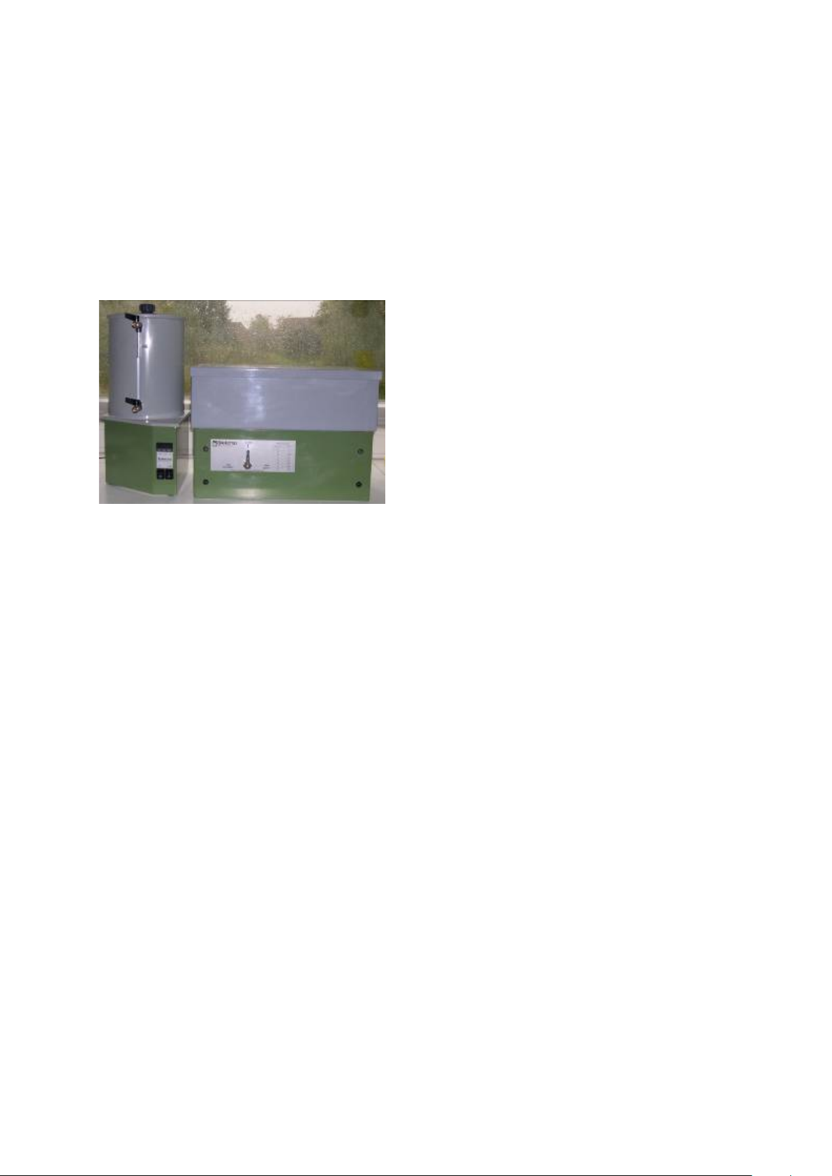
2Description of the sand / kaolin box
The sand/kaolin box (1) stands on four feet (2) and has a drainage system (4) inside it. This
box (1) is filled with very fine synthetic sand, which is covered by a layer of kaolin clay
(Kaolinite - also known as china clay). The lid (3) placed on the rilsaneted (specially
coated) box prevents evaporation. Nylon filter cloth is used to keep the kaolin layer clean.
The sample rings (13) are placed on top of this filter cloth, and are in contact with the
kaolin suction medium through it.
The pump (7) creates suction in the vacuum vessel (5) that is conveyed to the samples (13)
from the drainage system (4) through the sand and kaolin layers. An electronic regulator is
used to define the pressure level, while the pressure sensor, throttle valve (9) and sound-
absorber ensure that the pump creates the correct amount of suction. The pump can be
switched on using the pump button (12) while power can be switched on with the On/Off
button (11).
When tap A is switched to “supply” then water is transferred from the vacuum vessel (5) to
the box (1). If Tap A is switched to “Discharge”, with the appropriate Pump Settings, then
water will leave the box and install suction on the sand and kaolin layer. By opening tap B
the pressure in the vacuum vessel will equilibrate to the atmospheric pressure. Water is
released from the vacuum vessel by opening Tap C.
3Technical specifications
Item Specification
Soil sample rings
max. 40
Dimensions box
55.0 x 33.5 x 37.5 cm (l x w x h)
(excluding supply bottle and measuring device)
Operating range
100 – 500 hPa; 0.1 - 0.5 bar; pF 2.0 – 2.7
Vacuum system
Type: vacuum pump, vacuum tank and automatic suction
level control system
Contents
10 L
Accuracy
±10 hPa
Adaptor
220V to 24 V

4
Figure 1: Assembled Sand/kaolin box with numbered
components
9. Throttle valve
10. Display
11. Power switch
12. Pump switch
13. Samples
1. Box
2. Box Stand
3. Lid
4. Drainage Pipe
5. Vacuum vessel
6. Vacuum vessel cap
7. Pump
8. Pressure sensor
Tap A
13
1
2
3
4
5
6
7
8
9
10
11
12
Tap D
Tap B
Tap C
Tap A
5
4 Assembling the sand / kaolin box
All of the tubes are connected and tested for leakage before delivery.
Take care not to break the tube connections while unpacking.
Check that the intended electrical supply has the correct voltage (230 V).
Construct the sandbox using the following instructions (Numbers refer to Figure 1):
4.1 Set up the sand / kaolin box:
4.1.1. Place the sand/kaolin box on a sturdy table,
with Tap A facing the front and turned to the
‘Closed’
position. (Fig 2)
4.1.2. Place the Vacuum Vessel (5) to the left of the
box, and plug it into an electrical supply (230
V).
4.1.3. Make sure that Taps A, B, C and D are all
closed.
Figure 2: Setup box with taps closed
A
B
C
6
4.2 Check the Setup Values
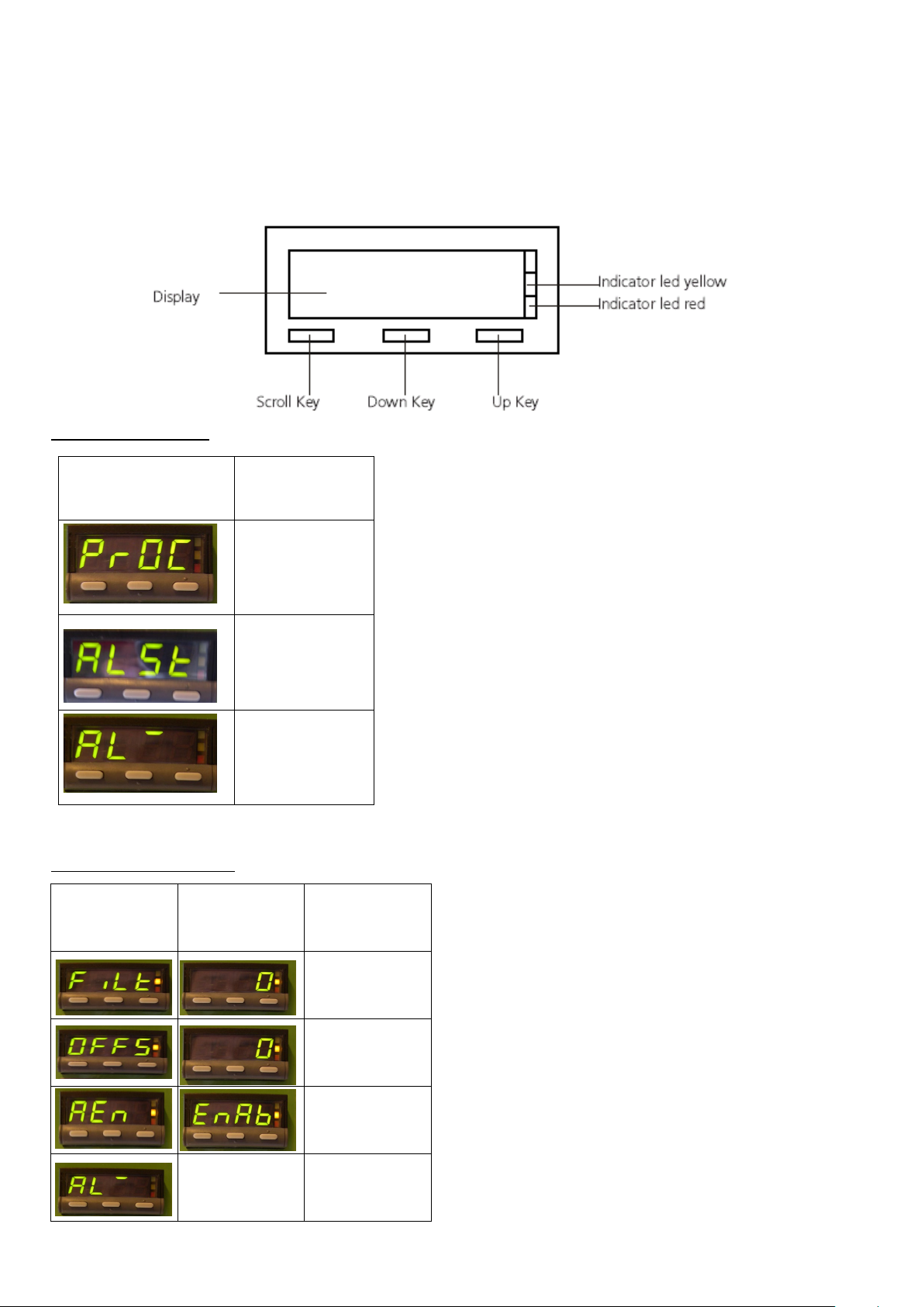
The Display (10 see figure 1 on page 4) facilitates access to a lot of extra
programming functions that should never be altered. Only adjust the settings
referred to in this manual.
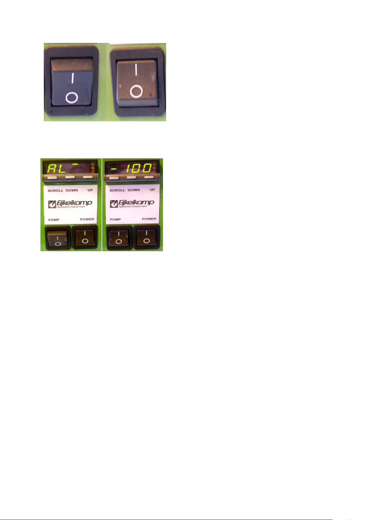
4.2.1. Check that the pump is switched off (Figure1:
12) and then turn the power on (11).
4.2.2. The red L.E.D flashes to indicate that you are
in the first menu. The pump indicator.
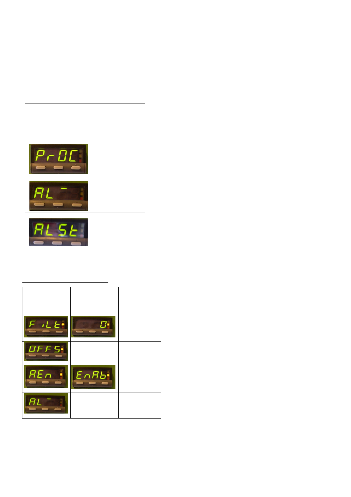
4.2.3. The First Menu has the three Parameters
listed in Table 1. The ‘default value’ displayed
is the current pressure in the Vacuum Vessel
(PrOC).
4.2.4. Hold the “Up-key” and “Down-key” down
simultaneously (for about 3 seconds) until
“FiLt” appears on the display. The yellow
L.E.D will be lighted to indicate that you are
in the Second Menu (See Table 2).
4.2.5. The first number displayed is the FiLt Setup
Value. Ensure that this is ‘0’ as seen in Table
2. If the FiLt Setup Value is not ‘0’, then use
the “Up key” or the “Down key” to correct it.
4.2.6. Press the “Scroll Key” twice to change
between Setup Names (E.g. ‘OFFS’ - See Table
2) and ensure that the Setup Values in Table 2
are installed.
Setup Name Setup Value Function
Input filter
time constant
value
Input offset
value
Enable access
to alarm value
Do Not Change Alarm value 1
Table 2: Second Menu
Parameter Meaning
Current Pressure
in the Vacuum
Vessel (12)
Alarm 1. Do not
change this
setting.
Pressure Set-
point
Table 1: First Menu

7
4.2.7. After all of the Setup Names have the First
Setup Values (Table 2) then use the “Scroll
Key” to return to the
‘FiLt’
Setup Name.
4.2.8. Push the “Up-key” and “Down-key”
simultaneously (for about 3 seconds) to exit
the second menu. The yellow L.E.D will
automatically turn off.
Note: Setup Values will be changed from the First Pump Settings (Table 2) for
removing the bubbles in the system, and in using the sand/kaolin box
(Chapter 5).

8
4.3 Prepare the Drainage System
The plastic drainage pipe (4) inside the box (1) must be covered with filter cloth. The
supplied filter cloth has two layers, and is 6 cm wide. The plastic drainage pipe needs top
be covered by 3 layers of cloth, so that sand wont block the holes in the pipe when suction
is applied, and the suction is diffused.
To apply the filter cloth to the pipe, the following steps should be followed:
4.3.1. Cut a 3.5m long section from the supplied roll
of filter cloth.
4.3.2. Cut down one side the filter cloth to make a
single 12cm wide layer.
4.3.3. To knot the cloth to the pipe, a 10cm long
section is cut into the each end of the strip to
form two ties. (Fig. 3).
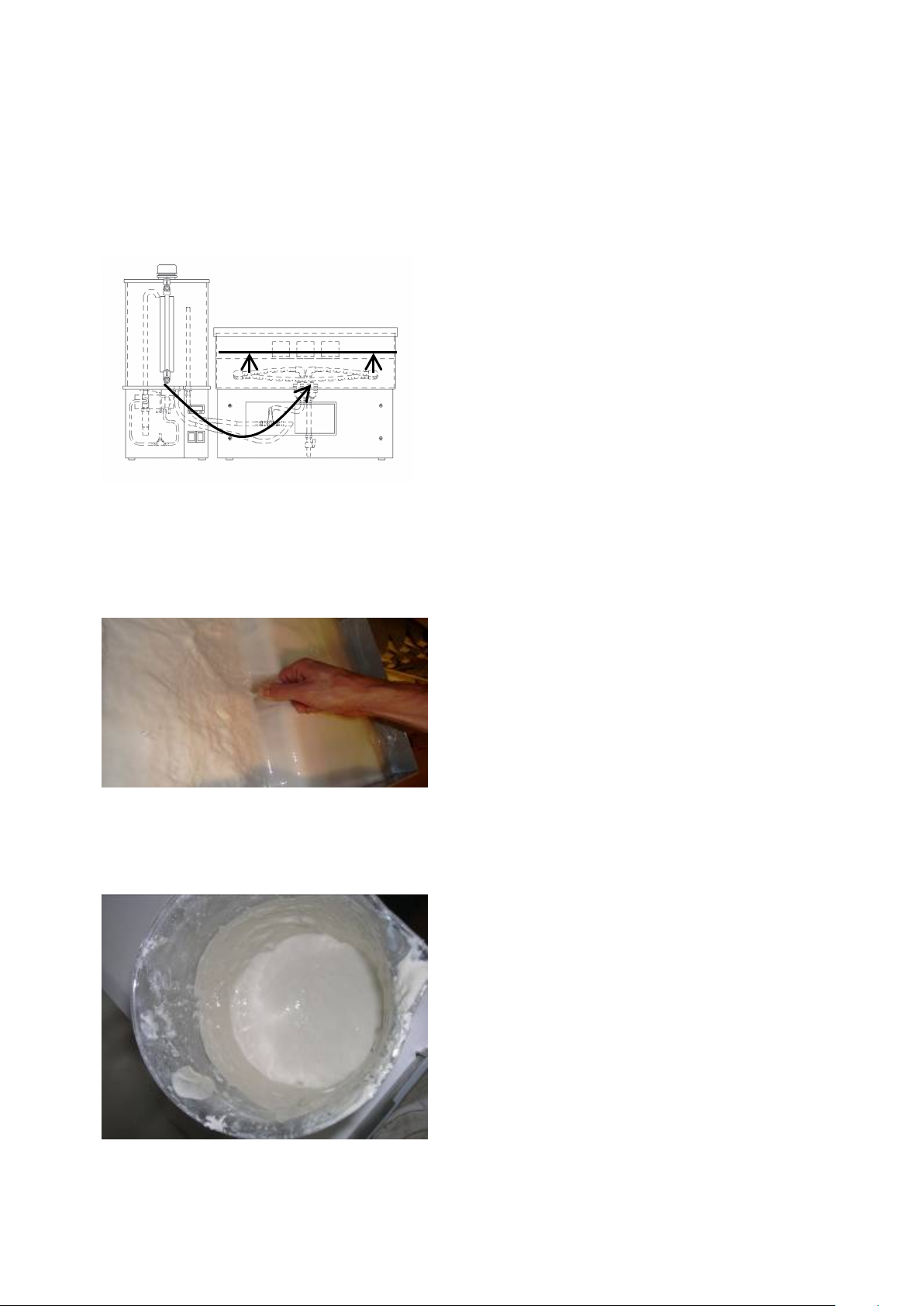
4.3.4. Saturate the filter cloth in water (Fig. 4).
4.3.5. Tie the filter cloth to one end of the drainage
pipe - where it enters the inside of the box.
4.3.6. Coil the filter cloth around the drainage pipe
so that each consecutive winding covers two
thirds of the width of the previous one. This
will ensure that the entire pipe is covered by
three layers of filter cloth. (Fig. 5).
4.3.7. Fasten the cloth at the other end of the
pipe.(fig.6)
4.3.8. Cut off the extra cloth, and tie the end to one
end of the drainage pipe.
Figure 6: Complete Cloth Covering
Figure 5: First cloth layer
Figure 3: The 10 cm long ‘ties’
Figure 4: Saturate Cloth
12cm
4cm
Three
layers
cloth
Pipe Surface
9
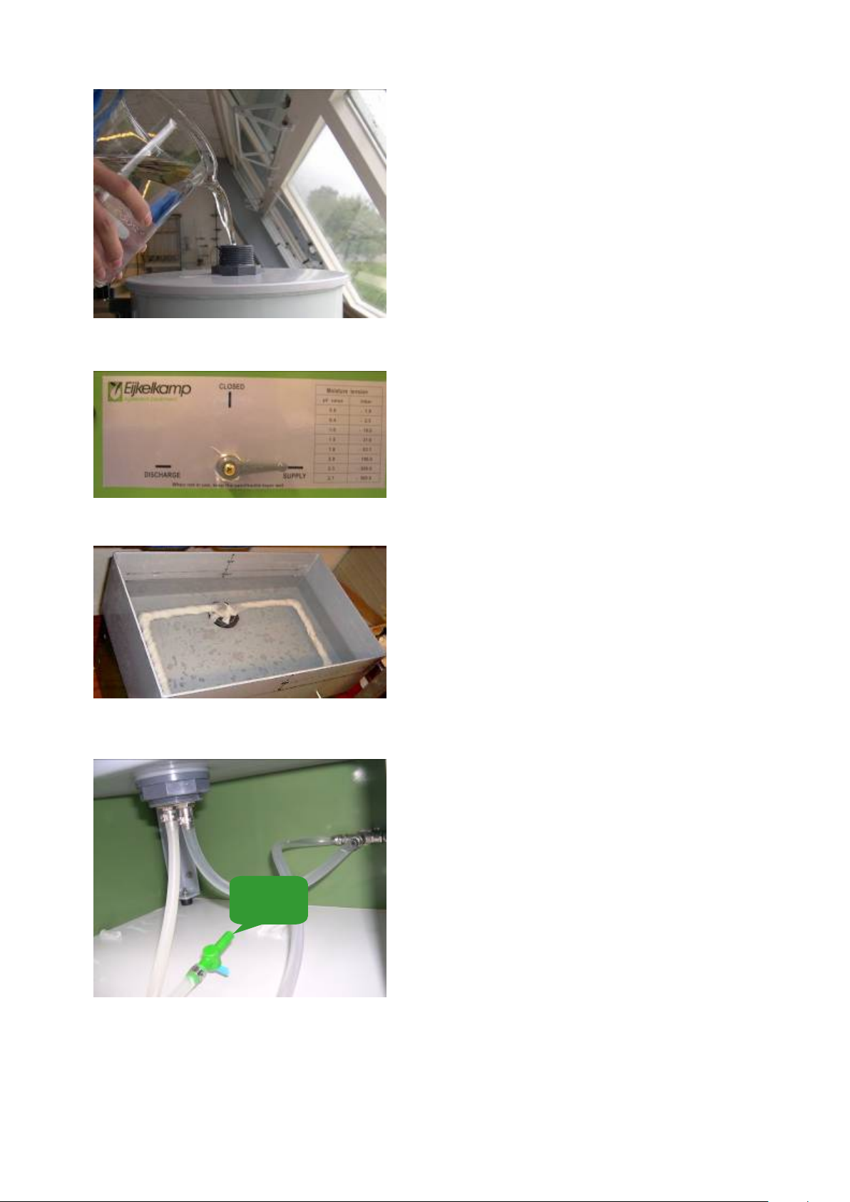
4.4 Removal of air-bubbles
4.4.1. Boil 10 L of demineralised water, and leave it
to cool.
4.4.2. Open the Cap (6) of the Vacuum Vessel and Fill
the Vacuum Vessel up to the ‘Max’ line with
this water. (This maximum is visible on the
tube between Tap B and Tap C). (Fig.7)
You may add (0.01mg/l) copper sulphate to
reduce microbiological activity.
4.4.3. Turn Tap A, on the front of the box, to
‘Supply’
.
Allow water to flow from the Vacuum Vessel
(5) into the Box (1) until the Drainage Pipe (4)
is completely submerged in water.(fig 8)
Always ensure the water level in the Vacuum
Vessel (5) is higher than the water level in the
Box (1).When the water level in the Vacuum
Vessel becomes too low then add
demineralised water through the open Cap
(6).
Water must flow from the Vacuum Vessel (5)
into the Box (1) until the Drainage Pipe (4) is
submerged.
4.4.4. When there are no bubbles left in the supply
tube between the Vacuum Vessel and the Box
then turn Tap A to the
‘Closed’
position
.
4.4.5. Gently pour water directly into the box (1)
until it is half-full. (Fig.9 )
4.4.6. Open Tap D, at the back of the box, and allow
some water to run from the box (1) out of Tap
D into a beaker. (Fig 10)
Figure 9: Half-fill box with water
Figure 7 Fill the Vacuum Vessel with
DM water
TAP D
Figure 10 : TAP D at backside of the box
Figure 8: Turn tap A to
‘Supply’
10
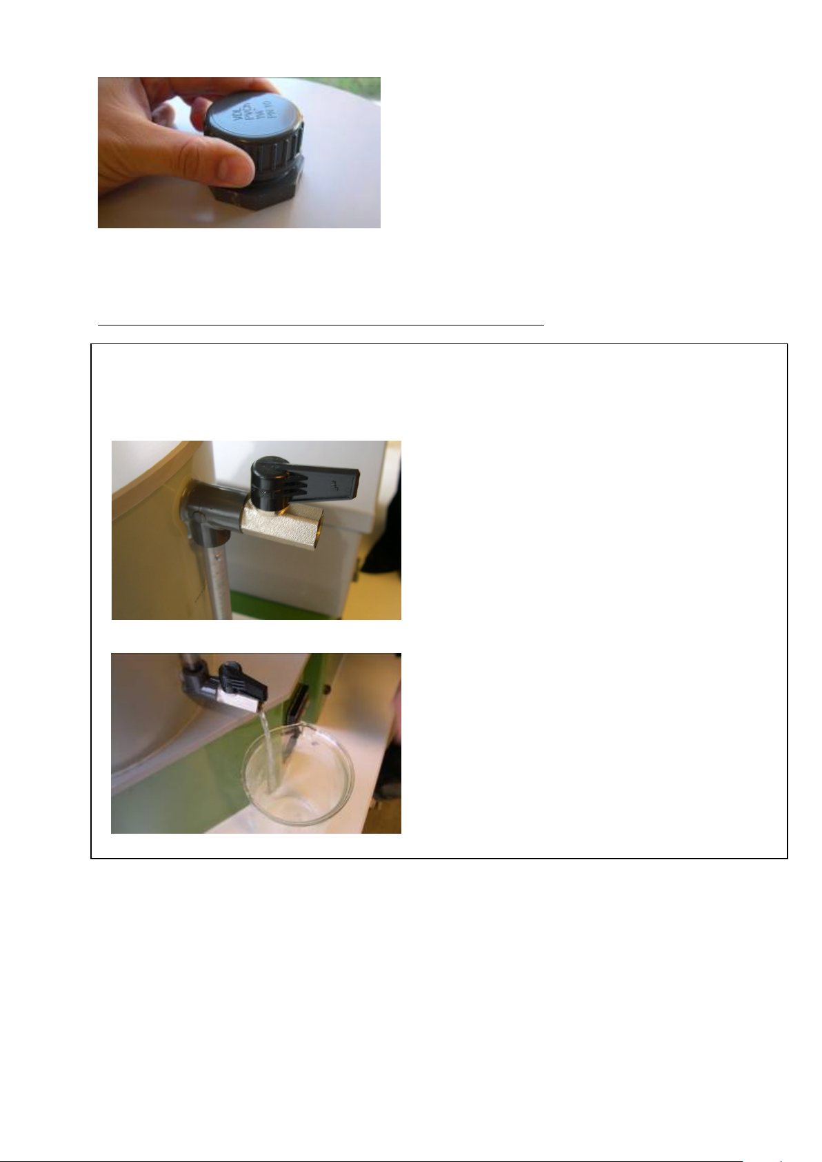
4.4.7. When there are no air bubbles in the tube
between the Drainage Pipe (4) and Tap D then
close Tap D.
4.4.8. Tightly close the lid of the Vacuum Vessel (5).
(fig 11)
When using the pump there are some important considerations (See Caption 1).
Caption 1: Controlling the water level in the Vacuum Vessel.
The water level in the Vacuum Vessel (5) must be constantly monitored. This level
should never exceed the ‘max’ on the clear tube between Tap B and Tap C.
When the water level in the Vacuum Vessel becomes too high, then follow these steps:
a. Turn Tap A to the
“Closed”
position and switch
off the Pump (12).
b. Gently open the pressure release valve (Tap
B), to allow the air-pressure to equilibrate
with the atmosphere.(fig12)
c. Place a beaker under Tap C, and open it to
allow the excess water to drain out of the
Vacuum Vessel.(fig 13)
d. Close Tap C when the water level in the
Vacuum Vessel (see glass tube) has drained to
about 4cm below the rim of the box (1). Close
Tap B.
e. Turn the pump back on and wait for the
pressure in the Vacuum Vessel to return to the
relevant value before returning Tap A to
“Discharge”.
Suction must be created in the Vacuum Vessel (5) to remove air bubbles from the
discharge tube between it and the Box (1).
Figure 11: Tightly close the lid
Figure 12: Open the pressure release valve
Figure 13: Water drain out with open the Tap
11
4.4.9. Check that the Pump is switched off (12: see
fig.1 on page 4) and the tap A, B, C and D are
closed, then turn the Power on (11: see fig.1
on page 4). Fig.14 pump is off now.
4.4.10.The red L.E.D flashes to indicate that you are
in the First Menu.
4.4.11. The First Menu has the three Parameters
listed in Table 1. The ‘default value’ displayed
is the current pressure in the Vacuum Vessel
(PrOC).
4.4.12.Press the “scroll key” twice (make contact
three distinct times less than 1.5 seconds
apart) until the ‘AL‘ Parameter is displayed.
4.4.13.Adjust the Set-point for the ‘AL‘ Parameter to
-100 hPa by pressing the “Down-key” or the
“Up-key”. (fig 15)
4.4.14.Press the “scroll key” twice so that the ‘PrOC’
name is displayed again.
4.4.15.Switch on the pump.
4.4.16.Switch Tap A to the position “Discharge”.
4.4.17. Some water will now be sucked into the
Vacuum Vessel (5). When there are no
bubbles between the Box (1) and the Vacuum
Vessel then turn the pump off.
Figure 15: Steps 4.411-4.413
Figure 14: Pump is off now

12
4.5 Laying the suction material
4.5.1 Saturate some synthetic sand with running
demineralised water and stir firmly to
remove air (Fig. 16).
There should be a high ratio of water to sand
so that it can be easily poured into the
box.(fig17) For the textural composition of the
sand see Table 3.
Table 3: Textural Composition of Sand
Particle size
diameter (mm)
Percentage
106
0
75
6.3
63
61.4
53
22.1
45
4.4
<45
5.8
Be careful to avoid damaging the drain system while stirring.
4.5.2 Slowly add the water-saturated sand to the
water in the sandbox (1) with a ladle while
stirring constantly to expel any entrapped
air.(fig 18)
The sand should be pressed against the side
walls of the sandbox, and into the corners, to
make sure that the sand does not contain air
pockets and a good seal between sand and
box is established.
4.5.3 When the water level in the Box (1) becomes
too high, then open Tap D – releasing the
excess water into a beaker.(fig 19)
Always retain a level of water in the box above the sand and the drainage system.
Figure 16: Saturate sand with water
Figure 17: A high ratio of water to sand
Figure 18: adding the water-saturate sand
Figure 19: Tap D open into bucket
13
4.5.4 Stop adding the saturated sand when the
sand level is 8 cm below the rim of the Box
(1).
Always ensure the water level in the Vacuum Vessel (12) is higher than the water
level in the Box (1).
4.5.5 Turn Tap A to the
‘Supply’
position, and open
Tap B. Water from the Vacuum Vessel (5) will
now flow through the drain into the sand and
remove final air residues.
The Vacuum Vessel Cap (13) must be open.
Keep 0.5cm of water above the surface level
of the sand.
4.5.6 Excess water (extra to the 0.5cm minimum
depth) can now be drained by opening Tap D.
(20)
These steps (4.5.5-4.5.6) must be done carefully: Any entrapped air cannot be
removed by this method after the Kaolin layer has been laid over the sand, because
the Kaolin and sand layers may become disengaged. The sand level must always
remain 0.5cm under water; otherwise air will be sucked into it.
4.5.7 Smoothen the surface of the sand with a
clean ruler, and leave it to settle for 1hr.(fig
21)
4.5.8 The Kaolin layer will now be added. Begin by
half-filling a large beaker with demineralised
water.
Be careful not to disturb the sand, or to mix the sand and kaolin layers.
4.5.9 Slowly add the kaolin powder to this beaker
while stirring the water.
4.5.10 Once the clay is completely saturated, spoon
it onto the surface of the sand using a large
ladle. Alternatively, pour it gently onto the
surface with the aid of a ruler. (fig 22)
4.5.11 The final Kaolin layer must be at least 1.5 cm
deep.
4.5.12 Allow the Kaolin to settle overnight – so that
there is a transparent layer of water above
the deposited clay.
Figure 21: Smooth sand with a clean ruler
Figure 22: Water-saturated Kaolin
clay
Saturated-sand
Flow
Flow
Flow
Figure 20 Water flow from vessel to box
14
When using the pump, the water level in the Vacuum Vessel must be checked
constantly (See Caption 1).
The pressure set-point for the Vacuum Vessel can now be set for flushing the sand /
kaolin suction medium.
4.5.13 Check that the pump is switched off (12), and
the taps A, B, C and D are closed.
4.5.14 Ensure that the lid of the Vacuum Vessel (5) is
tightly closed and the adaptor (230volt) is
connected to the power supply before
turning the Power On (11).
4.5.15The red L.E.D flashes to indicate that you are
in the First Menu.
4.5.16The First Menu has the three Parameters
listed in Table 1. The ‘default value’
displayed is the current pressure in the
Vacuum Vessel (PrOC).
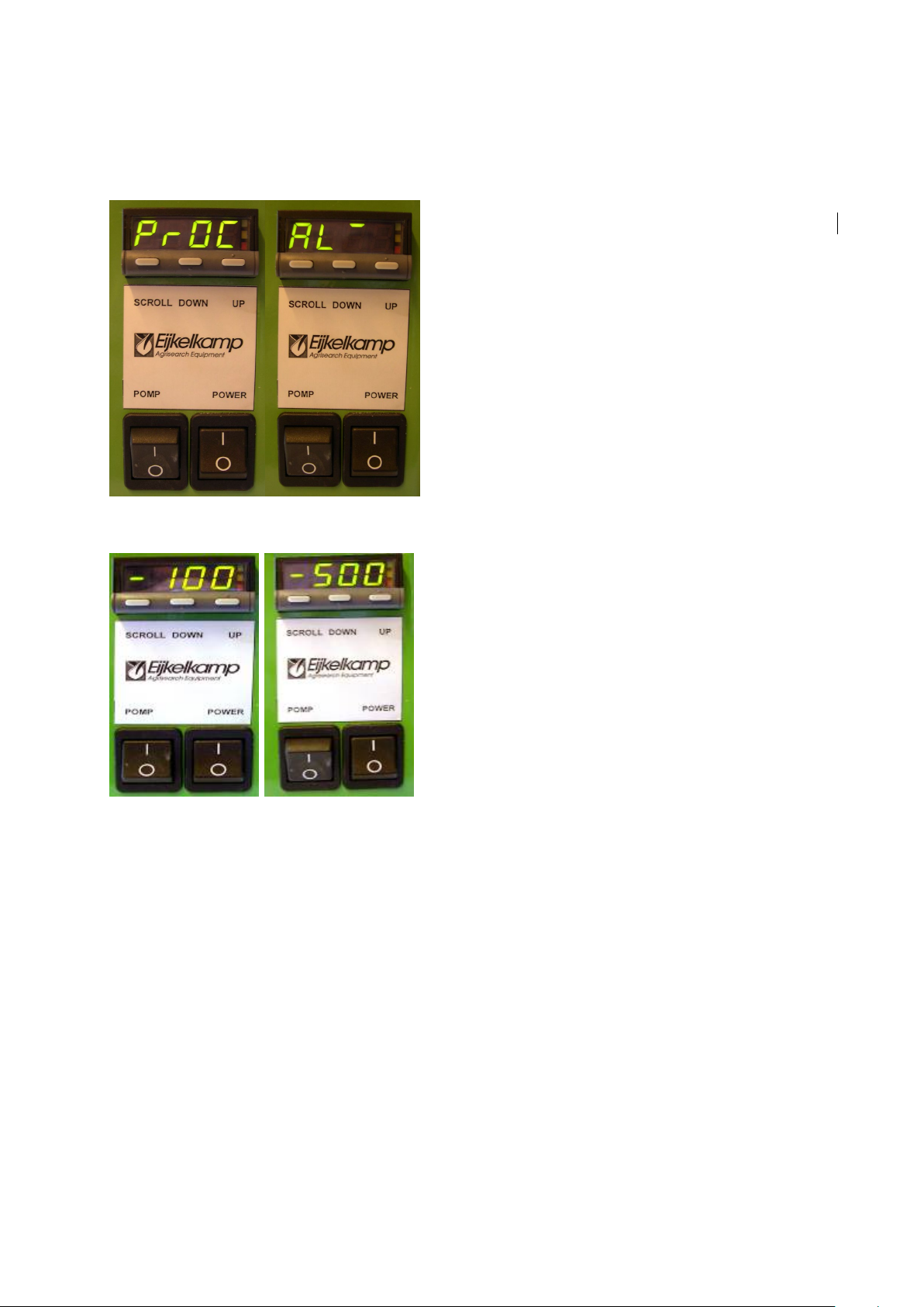
4.5.17 Press the “Scroll Key” thrice (make contact
three distinct times less than 1.5 seconds
apart) until the ‘AL‘ Menu is displayed.(fig 23)
4.5.18 Adjust the Set-point within the ‘AL‘ Menu to
–500 hPa by pressing the “Up-key” or “Down-
key”.(fig 24)
4.5.19 Press the “scroll key” twice so that the ‘PrOC’
name is briefly displayed.
A 1 cm deep stratum of water must always remain above the kaolin layer.
Figure 23: Display from (PrOC).to ‘AL‘
Figure24: ‘AL‘ change to-500

15
The sand/kaolin suction medium will now be flushed for a few hours to remove the final
air-residues, and bond the sand and clay layers.
4.5.20 Press the kaolin clay firmly against the walls
of the box, especially in the corners, to
prevent air-leakage.(fig25)
4.5.21 Smooth the surface of the kaolin layer level
with a clean ruler.
4.5.22 Gently pour boiled, demineralised water on-
top of the kaolin layer with the aid of a ruler.
Fill the rest of the box (1) with this
water.(fig26)
4.5.23 Turn on the Pump (12) and set Tap A to
“Discharge”.
4.5.24 Let the water be sucked through the kaolin
and sand into the Vacuum Vessel for a 2
hours – always gently topping-up the water-
level in the box when it becomes less than
1cm deep.
Constantly monitor the water level in the Vacuum Vessel (on the clear tube
between Tap B and Tap C). This level should never exceed the ‘max’ line
(See Caption 1).
4.5.25 After there are no bubbles appearing in the
pipe between the Drainage Pipe (4) and the
Vacuum Vessel (5) then the suction medium is
air-free.
4.5.26 Continue flushing the air-free sand/kaolin
with the remaining water until there is a 1cm
deep layer of water above the kaolin
layer.(fig 27)
4.5.27 Set Tap A to the
“Closed”
position and turn
off the Pump (12). (About 2hrs are spent
flushing the suction medium).
Although not strictly necessary, it is recommended to cover the kaolin with one layer of
filter cloth to prevent it from becoming too dirty.
Figure 26: Gently add demineralised water
Figure 25 : Press the kaolin against the walls
Figure 27: Remaining water a 1 cm deep

16
4.5.28 Cut the filter cloth to the correct size by
tracing around the lid of the box (1).
4.5.29 Saturate the filter cloth with water in a
beaker, before placing it onto the surface of
the kaolin layer. (fig 28)
4.5.30 Remove any air bubbles between the filter
cloth and the kaolin by gently smoothing it
from the centre outwards.
The sand/kaolin box is ready to use. There must be no air-bubbles in the system
from this point onwards. Vibration may cause a leak between the sidewalls of the
sandbox and the suction medium.
Figure 28: cover the filter cloth on the top of the sand

17
5 Using the sand/kaolin box
The environment around the sand/kaolin box should be kept at a constant
temperature between measurements, since temperature changes affect water
viscosity and therefore water retention values.
5.1 Prepare the Samples
5.1.1. Uncap the core sample ring. If the sampled
soil volume is larger than the volume of the
core ring, carefully remove excess soil by
‘chipping’ it off with a sharp edged tool.
Prevent smearing the sample surface so as
not to affect the physical properties of the
soil. (fig29)
5.1.2. Fix a piece of nylon cloth to the bottom side (sharp
edged side) of the sample with an elastic-band, or an
O-ring.
If the soil volume is less than the volume of the ring, or if the sample has been
damaged during transport, the sample should not be used for analysis. Samples
with large projecting stones may also have to be discarded.
5.1.3. Ensure that a 1cm layer of water is covering
the surface of the kaolin in the box (1).
Never turn Tap A to the “Supply” position or the bond between the sand and kaolin
layers will be broken. If water needs to be added to the box, then do so with
demineralised water, and pour it gently onto the kaolin surface with the aid of a
ruler. 5.1.4. Mark the rings, and draw a diagram of the box,
so that the rings can be replaced in exactly
the sample place after removal. (fig30)
The samples now need to be saturated. Steps 5.1.5 to 5.1.8 can be followed, or
alternatively an excicator may be used.
5.1.5. Place the soil sample with the bottom side
down in the sand/kaolin box. Let the sample
adapt for 1 hour.(fig 31)
1.
2.
3.
4.
Figure 30: Mark samples
Figure 31: Allow samples to adapt for 1hr.
Figure 29: Chip off excess soil – don’t smear!

18
5.1.6. Gently pour demineralised water onto the
kaolin surface with the aid of a ruler.
Raising the water level to quickly may entrap air in the samples or damage the
soil structure.
5.1.7. Stop adding water when the water level is 1cm
below the top of the sample ring.(fig 32)
5.1.8. Place a lid on the basin (to prevent
evaporation) and allow the sample to
saturate for 2 or 3 days (sandy soils) or up to
1 or 2 weeks (clayey soils).
Take care not to leave sandy soils wetting for too long since slaking may occur.
5.1.9. Take the ring carefully out of the water
/excicator and wipe off any water drops
hanging underneath the sample before
weighing it. (accuracy of balance 0.01 g). This
weight (including ring, cloth and elastic) is
used to calculate water content at saturation,
pF 0.(fig 33)
5.1.10. Record this weight as ‘Weight A’ in ‘Chapter 6:
Table 9’ for Processing the Results.(fig 34)
Note any irregularities that occurred during saturation (e.g. swelling of clayey
soils, changes in soil structure, accidental loss of soil material).
If an excicator was used in place of Steps 5.1.6 to 5.1.9 then ensure that a 1cm layer of
water remains above the surface of the kaolin in the box (1).
Water content measurements at pF 0 are relatively inaccurate:
•It is difficult to transfer the saturated sample to a balance without changing water content,
especially with sandy samples.
•The middle of the soil sample is used as the reference level for zero pressure, but the free
water level (h = 0) is in fact 1 cm below the top of the sample ring. The moisture tension
thus ranges from +1 cm at the bottom of the sample, to -4 cm at the top of the sample.
Note that at decreasing pressures this difference due to sample size becomes less
important.
Figure 32: Stop adding the water now
Figure 34: Weigh the Samples
Figure 33 : Take the ring out of the water

19
5.1.11.Place each sample ring at its designated
position on the kaolin surface. Press the ring
slightly, to improve soil - kaolin contact.(fig
35)
5.1.12. Ensure that the Pump is switched off.
5.1.13. Check that the electrical supply is plugged in
and the power (11) is turned on.
5.1.14. Make sure that the cap of the Vacuum Vessel
is closed tightly (6).
5.1.15. Turn Tap A to the
“Closed”
position.
5.1.16. Ensure Tap B is open and check that the
display shows ‘0’. If this is not the case, then
follow the correction steps under the heading
‘5.2
Set Offset Value’.
Figure 35: Place the sample at the exact the
Figure 36: Ensure Tap B is open
20
5.2 Set Offset Value
This section details how the neutral point for the electronic vacuum regulator is corrected
during use. If you are in the First Menu with Tap B open, and the PrOC parameter value is
not zero, then the atmospheric pressure has changed.
To correct this, execute the following steps:
5.2.1. The red L.E.D flashes to indicate that you are
in the First Menu (See Table 4).
5.2.2. The First Menu has the three Parameters
listed in Table 4. The ‘default value’ displayed
is the current pressure in the Vacuum Vessel
(PrOC).
5.2.3. Hold the “Up-key” and “Down-key” down
simultaneously (for about 3 seconds) until
“FiLt” appears on the display. The yellow L.E.D
will be lighted to indicate that you are in the
Second Menu (See Table 5).
5.2.4. The first number displayed is the FiLt Setup
Value. Press the “Scroll Key” twice until the
‘OFFS’ Setup Name is displayed.
5.2.5. If the PrOC parameter value (Current pressure
in the Vacuum Vessel) was +5 hPa when Tap B
was open then the Setup Value for the “OFFS”
Setup Name must be set to “-5” to
compensate for this.
5.2.6. Use the “Up-key” and “Down-key” to alter the
Setup Value for the “OFFS” Setup Name to
correct for the change in atmospheric
pressure. (See Table 5)
5.2.7.Use the “Scroll Key” to return to the
‘FiLt’
Setup Name.
5.2.8.Push the “Up-key” and “Down-key”
simultaneously (for about 3 seconds) to exit
the second menu. The yellow L.E.D will
automatically turn off.
5.2.9. The display must now show “0” for the PrOC
parameter value.
Setup Name Setup Value Function
Input filter
time
constant
value
-5 Input offset
value
Enable
access to
alarm value
Do Not Change Alarm value 1
Table 5: Reset Offset Value
Parameter Meaning
Current
Pressure in
the Vacuum
Vessel (12)
Alarm 1. Do
not change
this setting.
Pressure Set-
point
Table 4: First Menu
Table of contents
Other EIJKELKAMP Laboratory Equipment manuals


