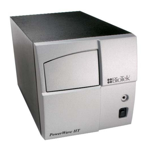
Bio-Tek PowerWave User manual

PowerWaveTM
Microplate Scanning Spectrophotometer
Operator’s Manual

.

PowerWave Manual Upate
Rev. C1, P/N 7261000
The following information pertains to revised instructions for unpacking and repackaging the
reader as shown in Figure 2-1, Chapter 2, page 2-2.
Figure 2-1 illustrates how to unpack the reader.
Figure 2-1: Unpacking and repackaging the reader
• Carefully open the top of the box, and remove the dust cover. The box will include a
power cord, an Operator’s Manual, and optionally, a Service Manual.
• Remove the end cap from the top of the reader.
• Lift the reader out of the box, and place it on a level surface. Remove the reader from
the plastic bag.
• Place all shipping material back into the shipping box for reuse if the instrument
needs to be shipped again.


Operator’s Manual
MANUAL PART #7261000
REV. C
COPYRIGHT1997
BIO-TEK INSTRUMENTS,INC.
For Research & Development Use Only
TM
ÿþýüûúùø÷ö ôýøóóþó
ò
ôúöý÷üûúñû÷ûðö÷öü

ii

iii
Notices ______________________________________________________
BIO-TEKINSTRUMENTS, INC.
Highland Park, Box 998
Winooski, Vermont
05404-0998
802-655-4040
800-451-5172
800-24-BIOTK (Service)
FAX: 802-655-7941 (Sales)
802-655-3399 (Service)
INTERNET: http://www.biotek.com
Lionheart Technologies Europe N.V.
Sneeuwbeslaan 33
B-2610
Wilrijk, Belgium
(32) 3-8290455
FAX: (32) 3-8254749
Copyright
© Copyright 1997, Bio-Tek Instruments, Incorporated. No part of this
publication may be reproduced, transmitted, transcribed, stored in a
retrieval system, or translated into any language without the written
permission of Bio-Tek Instruments, Incorporated.
Trademarks
Bio-Tek is a registered trademark, and PowerWave 200, PowerWave 340,
Extensions, RoboReader, KCJr, KCII, KC3, KC4, ELx 800 and ELx 808 are
trademarks of Bio-Tek Instruments, Inc.
Windowsis a trademark of Microsoft, Inc.
Restrictions and Liabilities
Information in this document is subject to change, and does not represent
a commitment by Bio-Tek Instruments, Inc. Changes made to the
information in this document will be incorporated in new editions of the
publication. No responsibility is assumed by Bio-Tek for the use or
reliability of software or equipment that is not supplied by Bio-Tek, or its
affiliated dealers.

iv
Revision Appendix
Revision Date Chapter Change
A 4/97 First Release
B 4/97 Front Pg Changed Enzyme Immunoassay
Analyzer to Microplate
Spectrophotometer.
Changed ELISA-based data to
microplate-based data.
Changed all references to
monochronometer to
monochromator.
B1 8/97 Inserted a Manual Update
correcting the calibration plate Part
Number.
C 8/97 Corrected Cal Plate PN in Chapters
1 and 4 to 7260522. Corrected Error
Codes in Appendix C. Added
accuracy and repeatability data to
Optical Specifications section. Added
Computer Control commands to
Appendix B.
Printed in the United States of America
Bio-Tek Printed Material Part No. 7261000

v
Warnings and Precautions
The PowerWave should be operated on a flat surface away from direct
sunlight or strong incandescent light. Excessive humidity should be
avoided.
Hazard Warnings
Warning! Power Rating. PowerWave’s must be connected to a power
receptacle that provides voltage and current within the specified rating
for the system. Use of an incompatible power receptacle may produce
electrical shock and fire hazards.
Warning! Internal Voltage. Always turn off the power switch and
unplug the power cord before cleaning the instrument’s outer surface.
Warning! Liquids. Avoid spilling liquids on the reader; fluid seepage into
internal components creates a potential shock hazard. Do not operate the
instrument if internal components are exposed to fluid.
Warning! Software. The microplate reader operator must follow the
manufacturer’s assay package insert when modifying software
parameters and establishing result calculation methods, using the reader’s
on-board software.
Warning! Data Reduction Protocol. The reader’s software will flag
properly defined controls when they are out of range. It will present all
the data with the appropriate error flags in order for the user to determine
their validity. Because there have been no limits applied to the raw
absorbance data, all information exported via computer control must be
analyzed completely.

vi
Precautions
The following precautions are provided to help you avoid damaging the
system:
Caution: Service. The system should be serviced by authorized service
personnel. Only qualified technical personnel should perform
troubleshooting and service procedures on internal components.
Caution: Environmental Conditions. Do not expose the system to
temperature extremes. Ambient temperatures should remain between 15-
40°C. System performance may be adversely affected if temperatures
fluctuate above or below this range.
Caution: Sodium Hypochlorite. Do not expose any part of the instrument
to Sodium Hypochlorite solution (bleach) for more than 30 minutes.
Prolonged contact may damage the instrument surfaces. Be certain to
rinse and thoroughly wipe all surfaces.
Caution: Power Supply. Only use the correct line voltage when operating
the Automated Microplate Reader. A four-position line voltage select
switch is used to adjust for different line voltages. This switch is located
on the power input module. See the section Adjusting line voltage input
range in this manual for more details.

vii
Electromagnetic Interference and Susceptibility
USA FCC CLASS A
Warning: Changes or modifications to this unit not expressly approved by
the manufacturer could void the user's authority to operate the
equipment.
This equipment has been tested and found to comply with the limits for a
Class A digital device, pursuant to Part 15 of the FCC Rules.
These limits are designed to provide reasonable protection against
harmful interference when the equipment is operated in a commercial
environment. Like all similar equipment, this equipment generates, uses,
and can radiate radio frequency energy and, if not installed and used in
accordance with the instruction manual, may cause harmful interference
to radio communications. Operation of this equipment in a residential
area is likely to cause interference, in which case the user will be required
to correct the interference at his own expense.
Canadian Department of Communications Class A
This digital apparatus does not exceed Class A limits for radio emissions
from digital apparatus set out in the Radio Interference Regulations of the
Canadian Department of Communications.
Le present appareil numerique n'met pas du bruits radioelectriques
depassant les limites applicables aux appareils numerique de la Class A
prescrites dans le Reglement sur le brouillage radioelectrique edicte par le
ministere des Communications du Canada.

viii
Based on the testing below, PowerWave bears the CE mark.
EC DIRECTIVE 89/336/EEC
EN 50081-1, CLASS A-Emissions
The system has been type tested by an independent testing laboratory and
found to meet the requirements of EC Directive 89/336/EEC for Radiated
Emissions and Line Conducted Emissions. Verification was to the limits
and methods of EN 55022. The device is classified as EN 55022, Class A.
EN 50082-1 Immunity
The system was also tested and found to meet requirements for
Electrostatic Discharge Susceptibility, Radiated Susceptibility, and
Electrical Fast Transient/Burst Susceptibility. Verification of compliance
was conducted to the limits and methods of EN 50082-1:1992; IEC 1000-4-
2:1995; IEC 1000-4-3:1995; and IEC 1000-4-4:1995.
Safety
This device has been type tested by an independent laboratory and found
to meet the requirements of:
North America
■Canadian Standards Association CAN/CSA C22.2 No. 1010.1-1992
Safety Requirements for Electrical Equipment for Measurement,
Control and Laboratory Use, Part 1: General Requirements
International
■IEC 1010-1 (1990) "Safety requirement for electrical equipment for
measurement, control and laboratory use. Part 1, General
requirements."
EC Directive 73/23/EEC Low Voltage Directive
■EN 61010-1 (1990) "Safety requirement for electrical equipment for
measurement, control and laboratory use. Part 1, General
requirements."

ix
Safety Symbols
The following warning and informational symbols may be found in
various locations on the PowerWave. Only qualified personnel who
recognize shock hazards and are familiar with the safety precautions
should use this instrument. Read the manual carefully before operating
this instrument.
Alternating current
Courant alternatif
Dreiphasen-Wechselstrom
Corriente Atterna
Corrente alternata
Earth ground terminal
Borne de terre
Erde (Bettriebserde)
Borne de Tierra
Terra (di funzionamento)
Protective conductor terminal
Borne de terre de protection
Schutzleiteranscluss
Borne de Tierra de Protección
Terra di protezione
On (Supply)
Marche (alimentation)
Ein (Verbindung mit dem Netz)
Connectado
Chiuso

x
Off (Supply)
Arrest (alimentation)
Aus (Trennung vom Netz)
Desconectado
Aperto (sconnessione dalla rete di alimentazione)
Caution (refer to accompanying documents)
Attention (voir documents d'accompanement)
Achtung siehe Begleitpapiere
Atención (vease los documentos incluidos)
Attenzione, consultare la doc annessa
Caution, risk of electric shock
Attention, risque de choc electrique
Gefährliche elektrische Spannung
Atención, riesgo de sacudida eléctrica
Alta tensione (in questo documento Alta tensione non
significa “tensione pericolosa” come definito in IEC 417)

xi
Intended Use Statement
The PowerWave is an eight-channel, automated, benchtop, general purpose,
Microplate Spectrophotometer which performs analyses of a variety of samples.
The Performance Characteristics of the data reduction software have not been
established with any laboratory diagnostic assay. The user must evaluate this
software in conjunction with the specific laboratory diagnostic assay. This re-
evaluation must include the establishment of new performance characteristics
for the specific assay.
This system is designed for use with a variety of microplate-based assays. Assay
protocol variations are addressed by the developer of the ELISA test kit, in
accordance with the test kit's procedure. A versatile curve fitting and statistical
software program is preloaded on every PowerWave. Plate templates and
formulas are automatically combined with the protocol assay setup. Data results
may be printed out, or sent to a computer running a Bio-Tek software package,
such as KC Jr. or KC4 for Windows. The software provides:
■ An easy-to-use, menu-driven interface;
■ Endpoint curvilinear regressional and statistical calculations;
■ Curve fitting, with 4-parameter, cubic, quadratic, linear, cubic-
spline, point-to-point and 2-P (Logit) methods;
■ Formula calculations for more complex mathematical operations;
■ Ability to define controls and positive and negative cutoffs;
■ Kinetic, with maximum slope, R-squared at maximum slope and
Onset OD Time analysis;
■ Scanning read mode to provide area under the curve calculations.
Specimen Preparation
Samples should be obtained, treated and stored following instructions and
recommendations contained in the package kit.

xii
About This Manual
The intent of this Operator’s Manual is to quickly instruct the new user
how to set up and operate Bio-Tek’s PowerWave. To help you read and
understand this manual, certain document conventions have been used.
iii Important information will be flagged in this manner, with the
information icon that appears at the beginning of this paragraph.
Major topic headings start a new page (such as About This Manual,
above) to give you a visual and style clue that a new major subject is being
introduced. One or more subheadings may appear below each major
heading.
Registration Card
Once the Microplate Reader has been set up, and is running successfully,
please take a moment to fill out and mail the postage-paid Warranty
Registration card. By sending in the registration card, you’ll be assured of
receiving prompt information on product enhancements.

xiii
Warranty
This Warranty is limited and applies only to new products, except for
computer-based software which is covered under a separate Warranty
Policy, manufactured by Bio-Tek Instruments, Inc. (“Bio-Tek”). Bio-Tek
makes no warranty whatsoever regarding the condition of used products.
Bio-Tek warrants the instrument (hereinafter collectively referred to as
“Products” or “Product”) for a period of one (1) year from the original
purchase date against defective materials or workmanship. This Warranty
is limited to the original purchaser (the “Purchaser”) and cannot be
assigned or transferred. All claims under this Limited Warranty must be
made in writing to Bio-Tek, Attention: Service Department. Purchaser
must ship the Product to Bio-Tek, postage pre-paid. Bio-Tek shall either
repair or replace, at its option and without cost to the Purchaser, any
Product which in Bio-Tek’s sole judgment is defective by reason of defects
in the materials or workmanship.
This Warranty is VOID if the Product has been damaged by accident or
misuse, or has been damaged by abuse or negligence in the operation or
maintenance of the Product, including without limitation unsafe
operation, operation by untrained personnel, and failure to perform
routine maintenance. This Warranty is VOID if the Product has been
repaired or altered by persons not authorized by Bio-Tek, or if the
Product has had the serial number altered, effaced, or removed. This
Warranty is VOID if any of the Products has not been connected, installed
or adjusted strictly in accordance with written directions furnished by
Bio-Tek. Batteries and fuses used in any of the Products are not covered
by this Warranty. Software utilized in conjunction with any of the
Products is not covered by the terms of this Warranty but may be covered
under a separate, Bio-Tek software warranty.

xiv

xv
Table of Contents
Notices............................................................................................. iii
Warnings and Precautions.............................................................. v
Intended Use Statement ................................................................. xi
Chapter 1 Introduction..................................................................1-1
Introducing the PowerWave ............................................................... 1-1
Quality Control....................................................................................1-2
Hardware Features.............................................................................1-3
Software Features...............................................................................1-3
Package Contents............................................................................... 1-4
Optional Accessories ..........................................................................1-4
Specifications...................................................................................... 1-5
Technical Support...............................................................................1-8
Chapter 2: Installation...................................................................2-1
The Operating Environment...........................................................................2-1
Unpacking and Repackaging the Instrument ............................................... 2-1
After Unpacking, Verify Performance............................................................2-3
Before Repackaging the Instrument..............................................................2-3
Adjusting the Reader’s Wavelength Table Setting.......................................2-4
Printing and Data Communications ..............................................................2-6
Installing a Printer...............................................................................2-6
Parallel Port Pin Definition..................................................................2-7
Setting Up the Serial Port Communications with Other Devices ........2-8
Attaching the Serial Cable ..................................................................2-8
Serial Port Pinout Description.............................................................2-9
Setting Up Communications Parameters............................................2-9
Changing the Baud Rate on the Reader...........................................2-10
Lamp Replacement ....................................................................................... 2-12
Bulb Removal....................................................................................2-13
Adjusting the Line Voltage Input Range .....................................................2-14

xvi
Adjusting the Fuse Configuration or Fuse Replacement.......................... 2-15
Other Utility Options.....................................................................................2-17
Setup Options...................................................................................2-17
Output Options..................................................................................2-19
Read Options....................................................................................2-20
Chapter 3: Operation.....................................................................3-1
Introduction...................................................................................3-1
The Keyboard .....................................................................................3-1
The Cooling Fan .................................................................................3-2
The Startup Screen .........................................................................................3-2
The Main Menu Screen ...................................................................................3-3
Define ...............................................................................................................3-4
Select Assay ....................................................................................... 3-4
Assay Name........................................................................................3-5
Define (Method, Map, Formula and Curve) ................................................... 3-6
Method..............................................................................................................3-6
Read Type.....................................................................................3-6
Delay in First Read........................................................................3-7
Incubation Temperature ...............................................................3-8
Single or Dual Wavelength............................................................3-9
Wavelength Selection..................................................................3-10
Number of Kinetic Reads/Kinetic Duration..................................3-10
Kinetic Interval ............................................................................3-11
Kinetic Number of Reads ............................................................3-12
Kinetic Duration........................................................................... 3-12
Shake Mode Selection ................................................................3-12
Shake Time.................................................................................3-13
Shake Speed...............................................................................3-13
Kinetic Data Analysis Selection...................................................3-14
Other manuals for PowerWave
1
Table of contents
Other Bio-Tek Measuring Instrument manuals
Popular Measuring Instrument manuals by other brands

Analytical Technology
Analytical Technology Q45C2 manual
Dahua Technology
Dahua Technology DH-TPC-BF5421-T Installation and configuration guide

Medem
Medem SafeAir CM installation instructions
THORLABS
THORLABS BP209-VIS operating manual
Extech Instruments
Extech Instruments LT45 user manual

Fuji Electric
Fuji Electric FE ZSS instruction manual
