BIOLAN GREYWATER FILTER 70 Parts list manual

70573300
BIOLAN GREYWATER FILTER 70
Instructions for installation, use and maintenance EN
11/2012
Serial No.
Assembler Date of manufacture
Seller's stamp, signature and date of purchase

2

EN-1
EN
Contents
Component list EN-2
Component drawing EN-2
1. Overview EN-3
2. Planning and selecting the location EN-3
2.1Technicalspecications EN-3
2.2 To be located above the ground EN-3
2.3 Location inside a residential building EN-3
2.4Conductingwastewatertothelter EN-4
2.5 Discharge point for the wastewater EN-4
3. Installation EN-4
3.1 Connecting the inlet and outlet sewer pipes EN-4
3.2Puttingtheltermaterialinplace EN-4
3.3 Opening the air valves EN-4
4. Use and maintenance EN-4
4.1 Follow-up of the operation EN-5
4.2Changingtheltermaterial EN-5
4.3Storingthelteroverwinter EN-5
5. Possible malfunctions EN-5
6. Disposal of the product EN-5
Biolan accessories EN-6
About the guarantee EN-6
BIOLAN GREYWATER FILTER 70
Instructions for installation, use and maintenance
The Biolan Greywater Filter 70 is a purifying unit for washing waters of one family,
especially designed for weekend residences. Into the lter may be conducted wash-
ing waters and waters from sauna as well as dishwashing and laundry waters. The
Biolan Greywater Filter 70 shall be installed above the ground. The wastewater is
conducted directly into the lter either by gravity or by pumping. The lter's treat-
ment capacity is 500 litres per day, which in practice is sufcient for 1–5 persons.

EN-2
EN
Part name Number Material
1 body 17733010 PE + urethane insulation
2 service door 17733020 PE + urethane insulation
3lterbox 17715060 ABS plastic
4 disk valve body 18733080 PP
5 disk valve 18715060 PP
6connectingpipe250x75mm 28733110 PP
7 branch sleeve 75 / 75 mm 28733120 PP
8 inlet pipe end 18715250 PP
9connectingange 18715110 PP
10 lip seal 19733130 EPDM
11 plug 75 mm 18715130 PP
12 rubber pad 19733060 EPDM
In addition to the components illustrated in the component drawing, the Greywater Filter 70 also in-
cludes:
attachment screw for rubber pad 20010016 RST
door latch 20080008 RST
attachmentscrewforange 20010011 RST
doorseal15x10mm 19733160 EPDM cell rubber
llingplugforurethane,grey 18715240 PE
user manual Finnish/Swedish 27733280 Paper
usermanualin10languages(exportproductsonly) Paper
ltermaterial 70574100 Package PE
Spare parts sales: dealers and the Biolan online shop at www.biolan.
Component list
3
6
5
2
10
4
7
8
9
1
12
11
Component drawing
EN-3
EN
1. Overview
ThepuriermeetstherequirementsoftheStateCouncil'sde-
cree (209/2011) on treatment of domestic wastewater outside
the sewer systems of the waterworks.
Wastewater from a WC or dry toilet in the property must be con-
ducted into a closed tank or treated otherwise in a due manner.
Rain- or stormwater or drainage water from foundations must
notbe conductedinto thelter.If installedin accordancewith
theinstructions,thetreatmentcapacityofthelterisabout500
litres per day, which in practice meets the need of washing water
for1–5people.The treatment capacityofthe lter materialis
good for about 100 days, after which it needs to be replaced in
accordance with the maintenance instructions.
Theoperationofthelterisbasedonmechanicalandbiologi-
calltrationofwastewater.Thedirtinthewastewatersticksto
theorganicltermaterialinthelter.Themicro-organismsliving
onthe surface ofthe lter materialuse the impuritiesas their
nutrition.
TheGreywaterFilter70comprisestwopurierunits,a.k.a.mod-
ules. The incoming wastewater is divided into the modules by
meansofthebranchsleeve(part7)locatedbetweenthemod-
ules.Bothmodulescontainvelterboxesplacedoneontop
of the other. The wastewater is conducted into the uppermost
lterboxes.Insidethelter,thewastewaterowsbygravitation
fromonelterlayertotheotherthroughtheopeningsintheend
ofthebox.
In Finland, building a wastewater system or chang-
ingitalwaysrequiresabuildingoractionpermission
from the municipal building authority or a submission
of notication of action. The building permission is
applied by submitting a relevant plan.
2. Planning and selecting the
location
2.1Technicalspecications
• dimensions of one module: (width x height x depth) 600 x
700x1010mm
• two modules side by side: width about 135 cm
• pipe connectors for Ø 75 mm sewer pipes
• heightdifferenceofinletandoutletconnectors(heightoffall):
530 mm
• capacity: about 500 litres a day
• weightwithoutltermaterial:2xabout38kg
2.2 To be located above the ground
The Biolan Greywater Filter 70 shall be installed above the
ground.Placethelterinalocationwherewaterwillnotgather,
evenwhenthere is ooding.Theltercan be installedout of
doors without a cover. The unit is thermally insulated, which
means it tolerates slight frost. If the lter is used in winter, it
must, however, be equipped with the Biolan Heating Cable,
whichisavailableasanoption,ortheltermustbeplacedin
a space, where the temperature stays above zero at all times.
The space required for use and maintenance must be taken
into account when selecting the location. A free space, at least
one metre deep, must be provided in front of the unit for chang-
ingtheltermaterial.Asufcientspacemustalsobeprovided
at the sides and the rear of the unit to enable maintenance of
the outlet connector for the sewer and the adjustment of the air
valvesintherearwall.Toensurethesupplyof oxygentothe
micro-organisms,theairexchangevalvesmustnotbecovered
ortheairexchangemustbearrangedinsomeotherway.
2.3 Location inside a residential
building
Biolan Greywater Filters are primarily intended for installation
outofdoors.Ifyouareplanningtoinstallthelterindoorsorin
closeproximitytoaresidentialbuilding(forexample,underthe
terrace),thensomemaintenancespacewithitsownentrance
should be provided. This space must also be provided with a
oorwelloranearthenoorforpossiblemalfunctions.
Thereplacement airforthe lteris takenfrom theend ofthe
discharge pipe and the outlet air is conducted as sewer ventila-
tion to the roof of the building. To avoid odour problems, the air
valves of the unit must be kept closed. The outlet air can also
be conducted through the upper air valve in the rear wall of the
lterintoaseparateoutletairchannel.Iftheunitisinstalledin-
doors,theoutletairchannelshallbettedwithanaspiratorthat
maintainsaslightnegativepressureinsidethelter.
Whenever the Greywater Filter is located in a warm
spaceinaresidentialbuilding,orincloseproximity
to a residential building, the correct installation must
alwaysbeveriedwiththeexpertinchargeofplan-
ningtheHVACsystemforthebuilding.

EN-4
EN
2.4 Conducting wastewater to the
lter
Thewastewaterisconducteddirectlytothelteralternativelyby
gravity,byowdrainageorbyapumpwell.Toensureaneven
distribution, the inlet pipe should be provided with a straight
80cm-longpartbeforethebranchsleeve(part7),thatreduces
turbulenceoftheincomingwaterow.
If you intend to utilise existing septic tanks during pumping,
these should be in good condition and hermetically sealed. The
operationofthepumpmustbesequencedusingatimersothat
duringonesequencethepumpwillfeedatmaximum20litres
ofwastewatertothelter.Theintervalbetweenthesequences
must be at least 10 minutes. The Biolan Timer, the Submersible
Pump and the Pump Well are available as an option.
2.5 Discharge point for the
wastewater
Conduct the treated wastewater to a suitable discharge point,
forexample astone pocketor anopen ditch.When planning,
bear in mind that the discharge of wastewater should be unob-
structed even when the level of the surface water or groundwa-
ter is high. If you route the water to an open ditch, provide the
endofthepipewithaaporanettopreventrodentsorother
small animals from gaining access.
Toxic
Hazardousto
the environ-
ment
Corrosive
Inammable
Oxidizing
3. Installation
Placethelteronarmandevensurfacethatisnotsusceptible
tofrost,suchas,forexample,abedofgravelorcrushedstone
oracastconcreteslab.Theltermustbeinahorizontalposi-
tionbothlengthwiseandlaterallytoallowthewastewatertoow
smoothlyovertheentirecleaningareaoftheltermaterial.
3.1 Connecting the inlet and outlet
sewer pipes
Whileinstallinggravityowsewers, asufcient gradient(ofat
least1-1,5%)needstobeprovidedtoallowthewastewaterto
owwithoutobstructionfromthe seweroutletofthe houseall
the way to the discharge point. There are inlet and outlet con-
nectors for 75 mm sewer pipes on both sides of the modules.
The inlet connectors are located at the upper edge and the out-
let connectors at the lower edge. Join the inlet connectors of the
modules together using the connecting pipes (part 6) and the
branchsleeve(part7).Connectthesewerpipecomingfromthe
building to the branch sleeve that joins the modules together.
Thebranchsleevedividestheincomingwastewateroweven-
ly into both modules. To ensure an even distribution, the inlet
pipe can be provided with a straight 80cm-long part before the
branch sleeve, that reduces turbulence of the incoming water
ow.Theoutletconnectorsfortreatedwaterarelocatedatthe
loweredgeofthelter,oneithersideofthemodules.
The treated wastewater can be conducted to the discharge point
either separately from each module or by joining together the
outlet connectors of the modules using an intermediate pipe,
and conducting the water out through the outlet connector of
one of the modules. The outlet connectors of the modules can
also be joined together using a similar branch sleeve that was
used in the inlet pipe. The discharge point for treated wasterwa-
ter can then be located between the modules. The unused inlet
andoutletconnectorsshallbeclosedusingtheplugs(part11)
includedinthedelivery.Ifthelterwillbeusedinwinter,theinlet
sewer must be insulated. Whether also the outlet sewer needs
to be insulated, shall be considered case by case.
4. Use and maintenance
The unit must be used and maintained in accordance with the in-
structions, and its operation must be monitored regularly. Main-
tenance of the wastewater system also involves maintenance of
the pump well and the septic tanks, if provided.
Intotheltercanbeconductedwashingwatersandwatersfrom
saunaaswellasdishwashingandlaundrywaters.Theltertol-
erates a small amount of anti-bacterial or chlorine-based agents
that are commonly used for cleaning. Follow the dosing instruc-
tions issued by the manufacturer of the detergent.
Wastewater from a WC or a dry toilet, rain water or stormwater,
or drain water from foundations must not be conducted into the
lter. Toxic chemicals or substances that contain such chemi-
cals, which can kill the micro-organisms that clean the waste-
water, such as drain openers, paints, oils or solvents, must not
beconductedintothelter.Harmfulchemicalscanbeidentied
from the markings on their packaging:
3.2Puttingtheltermaterialinplace
The lter material is packed in plastic bags for transportation.
Remove the plastic bags. Rip the lter material loose and
spreaditevenlyacrosstheboxbytappingitgently.Finally,draw
theltermaterialabout5cmtotherearfromtheV-openingsin
thedischargeendofthebox.
Theltermaterialboxesareidentical,buttheirdirectionshould
be observed – in the uppermost box water ows towards the
rearwall,inthenextboxitowstowardstheservicedooretc.In
thelowermostboxwaterowstowardstherearwall,fromwhere
it falls along the shaped bottom into the discharge sewer.
3.3 Opening the air valves
Theoperation ofthelter isbased onactivityof themicro-or-
ganisms.Thesemicro-organismsneedoxygentosurvive,and
therefore, it is vital to provide the lter with sufcient air ex-
change.Therearetwoadjustablediskvalvesforairexchangein
the rear wall of the modules. Set both disk valves of the module
about 10–20 mm ajar for the summer. In winter keep the valves
onlyslightlyajar(about5–10mm).Ifyouhaverealisedtheair
exchange by means of sewer ventilation, keep the air valves
completelyclosedtoavoidodourproblems(seepoint2.3).

EN-5
EN
4.1 Follow-up of the operation
Checktheoperationofthelteratleasttwiceduringeveryoper-
atingseason.Awell-functioninglterdoesnotgiveoffastrong
smell,theltermaterialinitremainsmoistandtheexitingwater
isclearandodourlessanddoesnotcontainasignicantamount
of solid matter.
Check that
1. wastewaterisowingsmoothlyinbothmodulesthroughall
theopeningsofthebox
2. theltermaterialhasbeendrawntoadistanceofabout5
cmfromtheopeningsinthedischargeendofthebox
3. theairexchangevalvesareinthecorrectpositionandthe
airisowingwithoutobstruction
4. the visible connections of the sewers are in order
5. thepuriedwastewaterisowingfreelyoutofthelter
4.2Changingtheltermaterial
Normally,theltermaterialoftheltermustbereplacedevery
100 days of operation. Only material, specially intended for use
inthe Biolanlters, shallbe usedasltermaterial.Biolan Oy
does not guarantee the purication capacity of the unit if any
otherltermaterialisused.
1. Changetheltermaterialofallboxesatthesametime.
2. Open the service door of the lter and draw out the lter
materialboxeskeepingtheminalevelposition.
3. Emptytheltermaterialintothecompostoruseitascover
soil for ornamental plants.
4. Relltheboxeswithnewltermaterial.Riptheltermate-
riallooseandspreaditevenlyacrosstheboxbytappingit
gently.Finally,drawtheltermaterialabout5cmtotherear
fromtheV-openings.
5. Check the inlet and outlet connectors for wastewater and
clean them.
6. Returnthe boxeslledwith ltermaterialtothelter unit.
The lter material boxes are identical, but their direction
should be observed – in the uppermost box water ows
towardstherear wall,inthenextboxitows towardsthe
servicedooretc.Inthelowermostboxwaterowstowards
the rear wall, and from there it falls along the shaped bottom
into the discharge sewer.
7. Make sure that the unit is on a level both lengthwise and
laterally so that wastewater will be evenly divided into both
modulesandowssmoothlyfromonelterboxtotheother.
8. Closetheservicedoorsoftheltercarefully.
9. Write down the service measures that were taken.
4.3Storingthelteroverwinter
Leavetheltermaterialboxesinsidethelter.Freezingofthe
ltermaterialdoesnotdamagetheunit.Iftheltermaterialis
still frozen when the operation starts in spring, thaw it by pouring
warm,clearwaterthroughthelter.
5. Possible malfunctions
Theltermaterialboxremainslledwithwater
Theltermaterialboxshalldrainoffbetweenthetimesofop-
eration.Ifthisisnotthecase,theltermaterialmaybeclogged.
1. Makesurethattheltermaterialhasbeendrawntoadis-
tance of about 5 cm from the openings in the discharge end
ofthebox.Asnecessary,pushtheltermaterialslightlyto
the rear.
2. Checktheageoftheltermaterial.Inheavyandcontinu-
oususe,theltermaterialmaygetcloggedalreadyduring
therst100daysofoperation.Replacetheltermaterial,
if necessary.
Fliesinthelter
TheairopeningsoftheGreywaterFilterarettedwithynets
ofsmallmeshsize.Despitethenets,smalliesorgnatsmay
sometimesestablishthemselvesinthelter.Ifiesareinterfer-
ingwiththelter,youcandoawaywiththemusingapyrethrin-
based insecticide. Consult your local garden centre to select a
suitable product.
6. Disposal of the product
The raw materials used are presented in the component list (see
page4).Disposeofeachpartasprescribed.Alwaysfollowthe
regionalandcollecting-point-specicinstructions.
PE = polyethylene
to collection of energy waste or recycling of plastic
PP = polypropylene
to collection of energy waste or recycling of plastic
RST = stainless steel
to recycling of metal
Paper
to recycling of paper
EN-6
EN
Biolan Oy
P.O.Box2,FI-27501KAUTTUA
Tel. +358 2 5491 600
www.biolan.
Biolan accessories
Availability varies from country to country. Consult your local dealer for details.
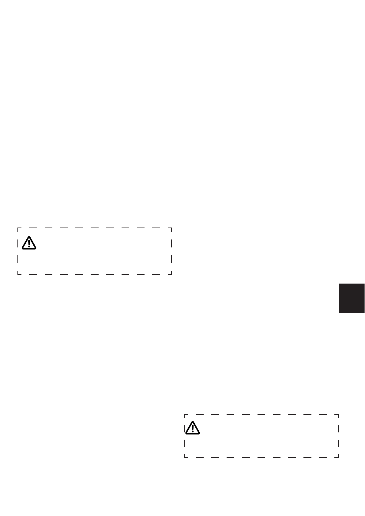
Biolan Filter Material
TheltermaterialfortheGreywaterFilter
ismadeofWarnstoraorCalliergonmoss
collected in connection with restoration of
lakes. The moss, which has grown under
conditions rich in nutrients, makes an ef-
cientandnaturalmaterialforpurication
of waste water.
Product no. 70574100,
HVACnumber3623604
Biolan Sampling Well
The Biolan Sampling Well is an accessory that
makes it easier to supervise the operation of the
wastewater treatment system, and enables reli-
able sampling of the wastewater. It is also suitable
for an underdrain well or a pump well.
Product no. 5713,
HVACcode3623605Biolan
Pumping Package
The Biolan Pumping Package is an acces-
soryforplaceswheregravityowdrainage
ofthewastewatertothelterisnotpossi-
ble. By means of the Timer the wastewa-
terisfedfromthePumpWelltothelter
in suitable doses. The Pumping Package
comprises three parts: Timer,
Submersible Pump and Pump
Well. The parts are also avail-
able separately.
Product no. 70577300,
HVACcode3623606
Comprises:
Timer 70577000,
HVACnumber3623608
Submersible pump 70577100,
HVACnumber3623609
Pump Well 70577200,
HVACnumber3623607
About the guarantee
TheBiolanGreywaterFilter70isguaranteedforveyears
1. The guarantee is valid from the date of purchase and cov-
ers possible defects in material and workmanship. The
guarantee does not cover any indirect damage.
2. Biolan Oy retains the right to decide about repairing or re-
placing damaged parts at its discretion.
3. Any damage resulting from careless or forcible handling of
the device, from failure to observe the operating instruc-
tions, or from normal wear, will not be covered by this guar-
antee.
4. Thebuyermustpresentadulylledoutguaranteecerti-
cate or a detailed purchase receipt when submitting claims
under the guarantee.
For matters related to the guarantee, please consult Biolan Oy
directly.


Table of contents
Other BIOLAN Water Filtration System manuals


Popular Water Filtration System manuals by other brands


Interpet
Interpet CF mini Instruction manual and set up guide

Nordson
Nordson 104 477A Technical publication

Red Sea
Red Sea Ocean Clear 317 Installation & operation manual

filtreau
filtreau UVC manual

Monarch Water
Monarch Water SCALEOUT ADVANCE SA-15 install guide

YAMIT
YAMIT F-700TS HYDROCYCLON Installation & operation manual


