Red Sea Ocean Clear 317 User manual

1
OCEAN CLEAR FILTERS
INSTALLATION AND OPERATION MANUAL
*Read instructions carefully before installing filter
1. Introduction to mechanical, biological, chemical and UV filtration.
In an aquatic environment organic particles (left over food, excrement, dead
algae etc.) are always produced, which if not removed will result in a high bio-
load that encourages the development of harmful bacteria. Also as fish digest
their food and as bacteria break down fish food and other organic matter,
ammonia, (which is toxic to fish) is set free into the water. The following types
of filtration methods are employed to remove these effects and maintain a
suitable environment.
Mechanical Filtration -is the physical removal of particulate matter from the
water.This is achieved by introducing a mechanical barrier in the water flow
that traps particles of a certain size according to the filter material used. A
mechanical filter is only effective when it is cleaned regularly, otherwise bacteria
will settle in and start breaking down the collected dirt, thus setting minerals
free into the water as well as becoming a bio-filter resulting in increased nitrate
levels.
Biological Filtration -is the process by which aerobic (nitrifying) bacteria of
the genus Nitrosomonas and Nitrobacter oxidize the toxic ammonia through
nitrite, (which is only slightly less toxic than ammonia) to the relatively harmless
nitrate. This process is known as nitrification, and in nature takes place in aquatic
habitats and soils where ammonia and sufficient oxygen are present.
The nitrifying bacteria develop naturally in an aquatic environment and will
colonize any suitable filter media such as the Polystrand filter pads supplied in
the Ocean Clear Filters. Once a biological filter media has been established it
should be disturbed as little as possible since the bacteria colony maintains its
level of activity according to the bio-load present in the system.
Chemical Filtration - in particular Active Carbon is used to absorb organic
material such as oxidation products of proteins, remains of fish medications
and organic toxicants. It is also effective in removing oxidation products that
are formed by ozonating seawater (slight amounts of chlorine and bromine).
Active carbon should be replaced regularly, since it gets saturated and as
bacteria settle on it, it will eventually work like an ordinary biological filter.
UV Filtration - Ultraviolet Filtration (sterilization) is a scientifically proven, reliable
and effective method for controlling and eradicating algae spores, bacteria and
protozoa present in the water source. Ultraviolet lights alter the DNA and RNA
of target organisms. UV Filtration is adversely affected by the clarity of the water
(particulate matter in the water reduces the kill rate). Therefore, mechanical
filtration that clarifies the water before the sterilization process, provides the
ultimate solution for aquarium and pond maintenance.
2. Description of Ocean Clear Filter models
The Ocean Clear Filters consist of a robustly designed canister intendend to
work under pressure and house various combinations of Mechanical, Biological,
Installation & Operation
Manual
For
Red Sea’s
Ocean Clear Filters
Red Sea

3. Components
The Ocean Clear Filter unit includes the following components:
Filter Body, Lid, and gray Thread Ring.
Filter media according to model (see above)
Parts pack - Drain Valve with garden hose thread outlet, 3/4" and 1" Straight
and Elbow Hose Adapters, 5" piece of 3/4" ID. Vinyl Tubing, 2 Speedy Clamps,
Vent Plug for Lid, 1/4' pipe Plug,
Pressure gauge (for models 317, 325, 340 and 375)
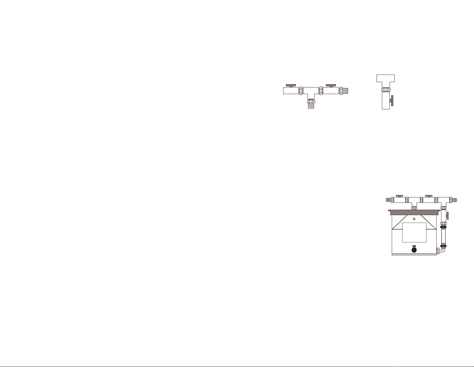
Model 354 - Valve system in two sections.
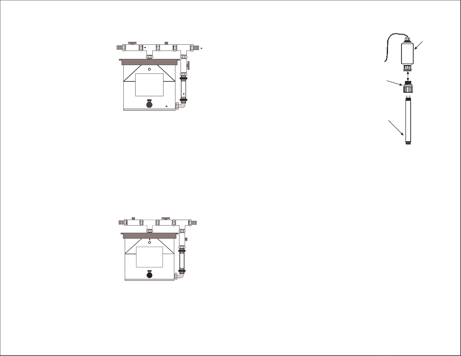
Model 375 & 380 UV Kit - Base Plate, Middle Pipe, Quartz sleeve, Transformer
& UV Lamp.
Instruction Manual & Product Registration Card.
The following additional equipment is required to operate and install the Ocean
Clear Filter: Roll of Teflon Tape; Flexible tubing; Water Pump.
4. Safety
IMPORTANT SAFETY INSTRUCTIONS (for Model 375 & 380)
WARNING - To guard against injury, observe the following safety precautions.
WARNING - UV radiation is harmful to the eyes and can be irritating to the skin.
Do not test the UV lamp outside of the filter body.
Note: UV radiation is not transmitted through the PVC lid and therefore viewing
the UV lamp through the lid is not harmful.
READ AND FOLLOW ALL SAFETY INSTRUCTIONS.
DANGER - To avoid possible electric shock, special care should be taken since
water is employed in the use of aquarium equipment. For each of the following
situations, do not attempt repairs yourself; return the appliance to an authorized
service facility for service or discard the appliance. If the appliance falls into
water, DON'T reach for it! First unplug it and then retrieve it. If any electrical
components get wet, unplug the appliance immediately.
a. Do not operate any appliance if it has a damaged cord or plug, or if it is
malfunctioning or if it is dropped or damaged in any manner.
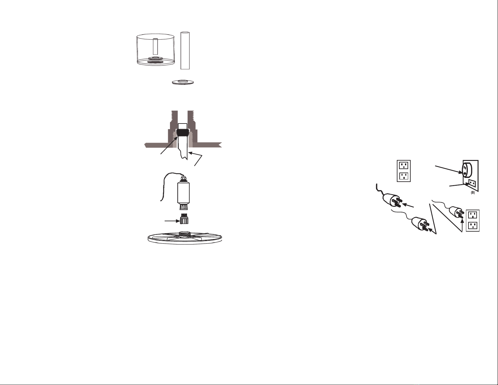
b. To avoid the possibility of the appliance plug or receptacle getting wet,
position aquarium stand and tank to one side of a wall mounted receptacle
to prevent water from dripping onto the receptacle or plug. A "drip loop"
shown in the figure, should be arranged by the user for each cord connecting
an aquarium appliance to a receptacle. The "drip loop" is that part of the
cord below the level of the receptacle, or the connector. Use an
extension cord if necessary,
to prevent water traveling
along the cord and coming
into contact with the receptacle.
If the plug or receptacle does get
wet, DON'T unplug the cord.
Disconnect the fuse or circuit
breaker that supplies
power to the appliance.
Then unplug the device and
examine for presence of water in the receptacle.
3
Aquarium
Drip Loop
Chemical and UV filtration media. Each filter configuration includes internal
channeling devices to ensure even flow throughout the filter bed. Based on
the size and bio-load of the system, optimal filtration may be achieved by
combining 2 or more Ocean Clear Filters connected in series. The Following is
a brief description of the various configurations currently available.
Model 317 Mechanical filter with triple density Polystrand Pads
Consists of 177 Sq. Ft of Polystrand Filter Pads in three gauges ranging from 100
micron at the water inlet, down to 50 micron before the outlet. The full flow
grid, set into the filter base ensures continued flow throughout the entire cross-
section of the filter material. This model includes a 30psi pressure gauge.
Model 318 Biofilter with Polystrand Filter Pads
Consists of 205 Sq. Ft of Polystrand Bio-media that has a continuously available
wetted surface area for nitrifying bacteria to colonize. It is advisable to install a
mechanical filter such as the Ocean Clear 317, 325 or 340 in front of the biofilter.
Model 319 Mechanical, Biological & Carbon Filter
Consists of 154 Sq. Ft of Polystrand Dual Function Filter Pads. The upper 100
micron Polystrand pads provide Mechanical filtration at the water inlet. The 50
micron Polystrand Bio-media around an Ocean Clear Carbon core provides
respectively biological and chemical filtration.
Model 320 Carbon Bio-Filter
Contains 7 lb. of Ocean Clear Carbon.
Model 325 Mechanical Filter with pleated Micron Cartridge and Carbon
Consists of a 25 micron spinbonded polyester filter cartridge to provide fine
mechanical filtration with a core of Ocean Clear Carbon. The 325 includes a
30psi pressure gauge. This filter must be used in combination with a Biofilter
such as the Ocean Clear 318.
Model 340 High Capacity Mechanical & Biological Filter
Consists of 40 Sq. Ft of 25 micron spinbonded polyester filter cartridge to
provide fine mechanical filtration with a core of 50 sq. Ft of Polystrand Bio-
media. The 340 includes a 30psi pressure gauge.
Model 354 Polybead Mechanical & Biological Filter
Contains 7lb. Of high density polyethylene spherical beads that provide superb
mechanical particulate filtration and supports the growth of nitrifying bacteria
for biological filtration.
Model 375 UV Sterilizer & Pleated Cartridge Filter
Consists of a 25 micron spinbonded polyester filter cartridge to provide polished
filtered water and an 18 watt UV sterilizer to kill harmful free floating bacteria
and algae.
Model 380 UV Sterilizer & Polystrand Filter
Consists of 154 Sq. Ft of Polystrand Dual Function Filter Pads providing Mechanical
filtration at the water inlet and an 18 watt UV Sterilizer to kill harmful free floating
bacteria and algae.
2

For models 317, 325, 340 and 375 thread the pressure gauge into the1/4" hole
located on the front of the Filter Body (do not over tighten). A 1/4" Plug is pre-
installed on models not requiring the Gauge.
Assembly of Model 354
Use Teflon tape and insert the 3/4” Hose Elbow into the 3/4“ threaded hole
located on the side of the base of the filter body, so that the Hose Adapter is
pointing upwards.
The Valve system is pre-assembled without Teflon tape in two sections:
a. The Top assembly (2 Valves, T & 3 Threaded Connectors ) with the “OUT”
Label.
b. The Side assembly (Valve, T, Threaded Connector & Hose adapter with
the “IN” Label.
Disassemble and thereafter reassemble each connection using Teflon tape, also
apply tape to the exposed threaded connectors. Using Teflon Tape,
select either the 1" or 3/4" Hose Elbow and screw into the valve labeled OUT
located on the Top Assembly. Select either the 1" or 3/4" straight Hose Adapter
and screw into the T labeled IN, located on the Side Assembly.
Screw the Top assembly into the threaded
hole inthe center of the filter Lid. Do not
over tighten.The inlet side of the Top
Assembly should now be positioned above
the Hose Elbow inserted into the side of the
base of the filter body. If this is not the case
release the gray Thread Ring
by turning it counter-clockwise.
Screw the Side assembly into the Top assembly
that is now attached to the Lid and tighten so that
the Hose Adapter screws into the valve of the
Side Assembly that is directly above the Hose Elbow located in the base of the
filter body. Connect the 2 Hose Adapters with the clear tubing provided and
secure in place with the Speedy clamps and tighten with pliers.
5
OUT
TOP ASSEMBLY
IN
SIDEASSEMBLY
OUT IN
OCEAN
CLEAR
FILTERS
c. Close supervision is necessary when any appliance is used by or near
children.
d. To avoid injury, do not contact moving parts or hot parts such as heaters,
reflectors, lamp bulbs, and the like.
e. Always unplug an appliance from an outlet when not in use, before putting
on or taking off parts, and before cleaning. Never yank the cord to remove
the plug from the outlet. Grasp the plug and pull to disconnect.
f. Do not use an appliance for other than intended use.The use of
attachments not recommended or sold by the appliance manufacturer may
cause an unsafe condition
g. Do not install or store the appliance where it will be exposed to the weather
or to temperatures below freezing.
h. Make sure an appliance mounted on a tank is securely installed before
operating it.
i. Read and observe all the important notices on the appliance.
j. If an extension cord is necessary, a cord with a proper rating should be used.
A cord rated for less amperes or watts than the appliance rating may overheat.
Care should be taken to arrange the cord so that it will not be tripped over
or pulled.
Save these instructions
5. Assembly
A number of external fittings (provided with the unit) must be attached to the
Filter before use. In addition, it is advisable to wash the filter media in running
water before installing the filter on your system.
To open the Filter, first remove the gray Thread Ring by turning it counter-
clockwise.
Remove Filter Lid. The Filter Body and Lid are sealed with an O-ring located at
the top of the Filter Body. Ensure that the O-ring does not get damaged (i.e.
by trying to remove it with a sharp instrument) as this will effect the sealing
of the unit. Remove filter media by lifting it out of the filter body.
For units that include Ocean Clear Carbon (models 319, 320 & 325) carefully
remove the Carbon Bag from its plastic wrapper. Rinse the Carbon Bag in water
to flush out any fines.
To reassemble the unit, return the filter media to the Filter Body making sure
that it is seated correctly. Centre the clear Lid on the body and replace the gray
Thread Ring, take care not to over tighten.Install the external fittings provided
in the parts bag as follows:
Insert the white Air Vent Plug into the 1/4" threaded hole in the Lid.
Insert the Drain Valve into the 3/4" hole located on the front of the base of the
filter body. Ensure that the valve is in the closed position and that the Safety
Cap of the valve outlet is securely closed.
Choose either the 3/4" or 1", straight or elbowed inlet and outlet Hose Adapters
according to the pump,and position the filter in relation to your system. If you
are planning to use 2 Ocean Clear Filters in line, use the 3/4" elbows on the
outlet of the first filter and inlet of the second. Using Teflon tape, thread the
inlet Hose Adapter into the 3/4" threaded hole located at the top of the Filter
Body. Insert the outlet Hose Adapter into the 3/4" threaded hole located on
the side of the base of the filter body. Do not over tighten the Hose Adapters.
4

Assembly of UV Kit - Model 375 & 380
Ensure that the white Base Plate is securely
in position in the bottom of the body.
Insert the gray Middle Pipe into the
center of the Base Plate ensuring that it is
standing vertically.
Insert the filter cartridge into the
body ensuring that it is firmly seated
in position. Center the clear Lid on to
the Body and replace the gray Thread Ring.
Quartz Sleeve
a. Check that the top of the Rubber Seal is
located approx. 3/8” from the top
of the Quartz Sleeve.
b. Carefully insert the Quartz Sleeve into
the hole in the center of the Connector
located in the center of the lid ensuring
that the sleeve is vertical and that
the Rubber Seal is seated firmly in the
Connector.
c. Place the Quartz Cap over the top of
the Quartz Sleeve that is protruding above
the Connector and screw tightly.
The Quartz Cap compresses the Rubber Seal
making the unit watertight.
d. Connect the assembled filter (without the
UV lamp module attached) to your pump as
described in the Installation instructions
below and check that the o-ring and
Rubber Seal have been installed correctly.
It is advisable to ensure that the water
pressure does not exceed 15 psi.
If any leaks occur repeat the above assembly instructions making sure that
the seals are clean and that the Quartz Sleeve is positioned correctly.
UV Lamp Module
a. Ensure that the Transformer is not connected to the power outlet, then
connect the lamp to the 4 pin lamp holder located at the bottom of the
Transformer.
b. Carefully insert the lamp (attached to the transformer) into the Quartz Sleeve
through the top of the Quartz Cap and screw the Transformer into position.
Do not over tighten the Transformer as this may create difficulty when it is
necessary to replace the lamp.
c. Do not plug the transformer into the power outlet until the complete unit
has been installed and water is flowing through the unit. A constant flow of
water is necessary to keep the Lamp operating within the desired temperature
range.
6
Quartz
Cap
Water tight seal
Rubber Seal
Quartz Sleeve
Base Plate
Base plate and Middle pipe
Middle
Pipe
6. Installation
Connect the Filter to your pump by using 3/4" or 1" flexible pipe according to
the Hose Adapters you have selected and use the Speedy Clamp (tightened
with pliers) to secure the flexible pipe to the Hose Adapter.
Attach a flexible pipe to the outlet Hose adapter to return the filtered water
to your system.
To connect 2 or more Ocean Clear Filters in series, position the filters side by
side so that the outlet of the first filter (with the 3/4" elbow Hose Adapter
pointing down) is above the inlet of the second filter (with the 3/4" elbow Hose
Adapter pointing up). Connect the 2 Hose Adapters together using the flexible
pipe provided and securing the pipe to the Hose Adapters with the speedy
clamps.
Grounding Instructions (for Model 375 & 380)
The OCF -UV 375 and 380 should be grounded to minimize the possibility of
electric shock. The OCF -UV 375 and 380 are equipped with an electric cord
having an equipment grounding conductor and a grounding type plug. This
plug must be plugged into an outlet that is installed and grounded in accordance
with all appropriate codes and ordinances.
The OCF -UV 375 and 380 are intended for use on a nominal 120 Volt circuit,
and has a grounding plug like
the plug illustrated in (A) below.
A temporary adapter illustrated
in (B) and (C) below may be used
to connect this plug to a two-pole
receptacle as shown in (B)
if a grounded outlet is not available.
The temporary adapter should be used
only until a grounded outlet can be
installed by a qualified electrician.
The green-colored ridge dear (lug, and the like)
extending from the adapter must be fastened
to a permanent ground such as a grounded outlet box.
7. Start-up
Loosen the white Air Vent Plug located on the Filter Lid, in order to prevent air
from being trapped in the filter after it has been filled with water.
Start the water Pump to circulate water through the filter system and tighten
the white Air Vent Plug in the Lid(s) after trapped air has been released.
Models 317, 325, 340 and 375 are supplied with pressure gauges to indicate
when the filter requires cleaning. To determine the regular operating pressure,
after start-up, momentarily stop the flow out of the filter to determine the
Maximum Pressure your particular water pump will produce as indicated on the
pressure gauge. Thereafter note the Starting Pressure reading when the filter
is clean and running normally.
7
Grounding
Pin
Adapter
(D)
Metal screw
Coverofoutlet
boxgrounded
(A)
(C)

QuartzCap
Transformer
UVLamp
9
Model 375 & 380
The UV Lamp should have an effective life span of about 14 months after which
time it should be replaced.
To replace the UV Lamp:
Unplug the UV Lamp Transformer and shut off the
water flow to the Filter. Unscrew the UV Lamp
Transformer from the Quartz Cap and carefully
lift the Lamp straight up out of the Quartz Sleeve.
Replace the Lamp, reassemble and
restart the filter as described above.
Note: The UV radiation may cause
discoloration to some of the plastic parts.
This is normal and will not effect the
performance of the filter.
9. To clean and/or replace filter media
Shut off the water flow to the Filter.
Lower the water level inside the filter by removing the safety cap and opening
the Drain Valve located at the base of the Filter Body.
A garden hose with a 3/4"connector can be attached to the outlet of the Drain
Valve.
Open the Filter by removing the gray Thread Ring and Filter Lid and remove
the filter material to be cleaned and/or replaced and treat the filter media as
instructed below.
Reassemble the filter making sure to wipe the O-ring with a clean cloth before
replacing the Filter Lid and restart as described above.
Model 375 & 380: unplug the UV Lamp Transformer and shut off the water
flow to the filter.
Open the Filter by removing the gray Thread Ring and Filter Lid (with UV module
attached taking care to lift the lid straight up so as not to damage the Quartz
Sleeve.
Clean the Mechanical Filter Media as described below.
Rinse using a garden hose with a nozzle. To get the best results direct the strong
stream of water between cartridge pleats.
A build up of some organic matter on the outside of the Quartz Sleeve, Middle
Pipe and Base Plate may occur. When cleaning or replacing the filter cartridge
wipe these items with a damp cloth to remove the organic matter.
Reassemble the filter making sure to wipe the O-ring with a clean cloth before
replacing the Filter Lid and restart as described above.
Start-up settings - Model 354
For normal operation the valves should be set as follows:
Drain Valve - Closed
Outlet Valve - Open
Side Valve - Open
Top Valve - Closed
8. Maintenance
All Chemical or Mechanical canister filters will clog over time due to the
unavoidable build-up of particulate matter, therefore regular maintenance is
required. The filters should undergo regular maintenance when either the
pressure reading (models 317, 325, 340 and 375) increases to halfway between
the Starting Pressure and the Maximum Pressure, or when the flow rate drops
to approximately half of that when the filter was clean.
Model 354
Can be cleared of particulate matter periodically by back-washing the system.
This can be achieved without disassembling the filter.
Switch off the pump supplying water to the filter and connect a garden hose
to the gray Drain Valve. Reset the valves as follows:
Drain Valve - Open
Outlet Valve - Closed
Side Valve - Closed
Top Valve - Open
Switch on the pump, water will now
flow down through the Polybeads
and wash particulate to the drain.
When Back-Wash is complete,
return all of the valves to the normal
operation settings.
The rate of water flow should increase
after each Back-Washing. The frequency
of Back-Washing required will depend on
the system bio-load.
OUT
OPEN CLOSED
CLOSED
IN
NORMALOPERATION
OCEAN
CLEAR
FILTERS
OPEN
OPEN
OPEN
CLOSED
CLOSED
OUT IN
BACKFLUSH
OCEAN
CLEAR
FILTERS
8

10
Polystrand Mechanical filter pads - models 317, 318, 319 & 380
The tough Polystrand Filter Pads can be cleaned and reused many times and
will maintain a higher filtration efficiency if they are not allowed to get too
dirty! To clean, rinse each pad in a strong stream of water.
To clean imbedded organics, soak the Filter Pads in a 2 gallon bucket of water
with 2 cups of liquid bleach for 6 to 8 hours before rinsing. It is important
to flush all of the bleach out of the Polystrand filter pads before returning
them to the filter.
Polystrand Bio-filter - models 318 & 340
When conducting regular maintenance on a filter containing a Polystrand Bio-
filter place the Bio-filter in a container of tank water to maintain biological
activity. Due to the build up of organics, over time the Polystrand Bio-filter
material may clog. There are a number of layers of Polystrand filter pads
throughout the filter. To improve flow through the filter without destroying
the biological activity clean the filter media in sections, a few layers at a time.
Allow for at least a week between each section, thereby permitting biological
activity to re-establish in the cleaned sections.
Ocean Clear Carbon - models 319, 320 & 325
Should the Ocean Clear Carbon become clogged with particulate matter it may
be washed during regular maintenance to restore better water flow. It is
preferable to use water taken from the aquarium so as to preserve any biological
activity that may be present. The effective life of active carbon varies according
to the conditions of each individual system. As a guide the 20 oz Ocean Clear
Carbon for models 319 and 325 should be replaced approximately every 2 - 3
months. The 7 lb Ocean Clear Carbon for the model 320 should be replaced
approximately every 6 - 9 months.
25 Micron Ocean Clear Pleated Cartridge - models 325, 340 & 375
The 25 Micron Cartridge can be cleaned and reused several times. Before
cleaning, remove any additional filter material present in the center of the
Cartridge.
Clean the dirty Cartridge by soaking it in a 2 gallon bucket with 2 cups of liquid
household bleach for about 8 hours.
Rinse using a garden hose with a nozzle. To get the best results direct the strong
stream of water between cartridge pleats.
9. Warranty
Red Sea Fish Pharm Aquarium Products Limited Warranty
The limited warranty sets forth all Red Sea Fish Pharm LTD (Red Sea) responsibilities
regarding your product. There are no other express or implied warranties from Red
Sea.
Red Sea warrants your product against defects in materials and workmanship for
a period of 12 months from the date of original purchase and will repair this product
free of charge (not including shipping costs) with new/rebuilt parts. In the event
that a problem develops with this product during or after the warranty period
contact your dealer or Red Sea (at the company address indicated) for details of
your nearest authorized service center.
This warranty is extended only to the original purchaser. Proof of date of purchase
will be required before warranty performance is rendered.
This warranty only covers failures due to defects in materials or workmanship which
occur during normal use. It does not cover damage which occurs in shipment or
failures which result from misuse, abuse, neglect, improper installation, operation,
mishandling, misapplication, alteration, modification or service by anyone other
than an authorized Red Sea service center.
Red Sea shall not be liable for incidental or consequential damages resulting from
the use of this product, or arising out of any breach of this warranty. All express
and implied warranties, including the warranties of saleability and fitness for a
particular purpose, are limited to the applicable warranty period set forth above.
These statements do not affect the statutory rights of a consumer.
USA
Some states do not allow the exclusion or limitation of incidental or consequential
damages, or limitations on how long an implied warranty lasts, so the above exclusions
or limitations may not apply to you.
Red Sea
Visit our Website at:
www.redseafish.com
International Office:
Free Trade Industrial Zone
P.O. Box 4050 Eilat 88000, Israel
Tel: 972 (9) 9567107
Fax: 972 (9) 9567110
E-Mail:[email protected]
USA Office:
18109 Ammi Trail Houston,
Texas 77060
Tel: 281 447 0205
Fax: 281 447 1153
E-Mail:[email protected]
European Office:
Z.A. de la Saint-Denis,
F-27130 Verneuil s/Avre, France
Tel: (33) 2 - 32377137
Fax: (33) 2 - 32377136
E-Mail:[email protected]
This manual suits for next models
8
Table of contents
Other Red Sea Water Filtration System manuals