Blagdon Inpond 5 in 1 2000 User manual

www.blagdonwatergardening.co.uk
Search Blagdon Water Gardening for support videos
inpond 5 in 1
2000
Instant solution for a
clear and beautiful pond

inpond
2000
Congratulations on buying an inpond 5 in1
Manufactured with advanced technology to
create a clean and healthy pond for your fish.
IMPORTANT
Please attach proof of purchase to this manual
and file in a safe place.

CONTENTS
Getting to know your Inpond 2000
Parts Descriptions / spares codes - with exploded diagram
Pump performance / flow chart
Specification chart
Installation
Electrical Installation
Installing UVC
UVC Electrical Installation
Installing Inpond
Maintenance and cleaning
Cleaning
Step by Step guides
Routine Maintenance
Annual Maintenance
Winter storage
Troubleshooting
Troubleshooting and maximise performance
Faults - problem procedure
Consumer advice contact details
Guarantee
2
2,3
4
4
5
6
6
6
10
13
13
14
14
17
17
18
18
20
21
21

GETTING TO KNOW YOUR INPOND 2000
1
2
3
4
5
22 23 24 25 26 27 28
14 15 16 17 18 19 20
40 41 42
36
35
34
33
32
31
30
39
38
37
2
13
12 6
7
8
9
10
11
29
43

3
GETTING TO KNOW YOUR INPOND 2000
No. Part Description Spare Code
1. Filter Lid N/A
2. Green Foam 1054690
3. Polymer Wool Cartridge N/A
4. Polymer Wool Pad 1054690
5. UVC Viewing Window N/A
6. UVC Contact Chamber Screws N/A
7. UVC Contact Chamber N/A
8. Lid Locks N/A
9. UVC Magnet N/A
10. Ceramic Media 1051187
11 . Filter body N/A
12 . IP68 Starter UVC N/A
13 . UVC Mains Cable N/A
14 . UVC Electronics & Cap N/A
15 . UVC Body N/A
16. UVC Quartz Sleeve Yellow Lock Cap N/A
17. UVC O ring N/A
18 . UVC Quartz Sleeve Holder N/A
19 . Pl 5W UVC Lamp 10 410 41
20. 5W Quartz Sleeve N/A
21. Outlet Locking Nut N/A
22. Double Threaded Attachment N/A
23. Connecting Pipe N/A
24. Pump Locking Nut N/A
25. Impellor Cover N/A
26. Impellor cover O ring N/A
2 7. Impellor Complete 1040556
28. Pump Motor unit N/A
29. Pump Cable N/A
30. LED Spot Light Body N/A
31. Thread N/A
32. LED Spot Light O Ring 1055840
33. LED Body N/A
34. LED Lamp 1w 1055840
35. LED Lamp Cover Clear N/A
36. LED Lamp Screw Cap N/A
37. Pump Outlet N/A
38. Ball Joint Socket 1017 76 3
39. Black Extension pipe 1017 76 3
40. Water Bell Large 1017 76 3
41. Super Daisy 1017 76 3
42. Daisy 1017 76 3
43. Flow control valve 1017 76 3

GETTING TO KNOW YOUR INPOND
Pump performance / flow chart
4
FEATURES
• Everything needed for a clear and healthy pond, combined efficient pump and
filtration package
• Low voltage pump/filter includes:
- 3 attractive fountain features
- mechanical & biological filter
- polymer wool cartridge
- UV clarifier
• Includes automatic night time LED spot light with pivoting feature
TECHNICAL DATA - PUMP
• 230 Volt • 50 Hz • 10 Watts
• 650 ltrlhr (143 gallhr) max flow
• Max pumping height: 1.25m (4’1”)
• 10 metre cable
• IP68 • Approved
TECHNICAL DATA - UVC
• 230 Volt • 50 Hz
• 5 Watt UVC lamp
• 10 metre cable
• IP68 • Approved
TECHNICAL DATA - LED
• 1 Watt
THIS 5 IN 1 WILL MAINTAIN THE FOLLOWING POND SIZES:
THIS MODEL
1.5m 79 ltrlhr 200 ltrlhr 835 ltrlhr
1.0m 185 ltrlhr 300 ltrlhr 870 ltrlhr 1626 ltrlhr
0.5m 300 ltrlhr 520 ltrlhr 1250 ltrlhr 2371 ltrlhr
0m 650 ltrlhr 700 ltrlhr 1500 ltrlhr 3000 ltrlhr
MODEL 2000 3000 6000 9000
Model &
Pond Size
Category
Deep
without fish
Deep
with fish
Shallow
with fish
Deep with fish
in full sun
Shallow
with fish in
full sun
Shallow
with Koi in
full sun
Filter &
Waterfall
Fountain,
Filter &
Waterfall
2000
SMALL
POND
2000 ltrs
440 gals
1334 ltrs
293 gals
1000 ltrs
220 gals
1000 ltrs
220 gals
750 ltrs
165 gals
375 ltrs
82 gals
N
/
A N
/
A

5
THIS 5 IN 1 WILL MAINTAIN THE FOLLOWING POND SIZES:
“The power supply must meet the specification of the product.
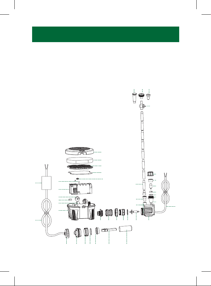
Inpond Pump
The cores in the supply cable are coloured in accordance with the following code:
Brown = Live, Blue = Neutral.
The electric cable is permanently connected and sealed in the motor body.
If the supply cable is damaged the pump must not be used.
Do not use the supply cable to lift the pump as this may cause damage.
For permanent installations to the mains supply, it is necessary to conform to the
regulations of the local electricity authority and this would include the use of a metal or
plastic conduit to protect the cable.
Attention has been drawn to the fact that special rules may exist concerning the installation
of your pond pump (i.e. local building regulations).
These pumps must not be used in swimming pools, or areas where people are in contact
with the water.
Always disconnect the mains electricity supply whilst the equipment is being installed,
repaired, maintained or handled. Consult a qualified electrician if in any doubt about
wiring this product to the main supply.
INSTALLATION
WARNING - All Inpond models must be used with an RCD
A Residual Current Device (RCD), also know as the Residual Current Circuit
Breaker (RCCB), with a tripping current not exceeding 30mA must be nstalled
in the supply circuit.
A means of disconnection from the supply having a contact separationof at least 3mm in
all poles must be incorporated in the fixed wiring.
Warning - The Inpond pump is provided with a thermal cut out that
temporarily switches off the pump in case of overheating and the pump may
automatically restart.

6
UVC INSTALLATION
UVC Lamps & quartz sleeve maintenance
The UVC lamp must be replaced every six months / once a season. It is recommended that
the lamp is replaced in the spring.
The Quartz sleeve can become coated in lime scale build up in hard water areas. This
should be carefully removed from the quartz sleeve and cleaned with a soft cloth.
A wet test must be carried out after maintenance to ensure there are no leaks before the
UVC is reconnected. pond/water feature.
Wet testing the UVC
Testing/replacing the UVC lamp
See Page 7 for illustration
1. Unlock the green UVC electronics cap.
2. Inspect the UVC cap and Quartz sleeve for water leaks.
3. Then unlock the yellow quartz sleeve end cap and unplug the lamp to replace if
desired
Warning - 1) Always turn off the power before any maintenance to the UVC
section 2) Always view the UVC lamp through the viewing window on the UVC
Chamber 3) Direct exposure to UVC light can damage your eyes and skin.
Caution - Inpond UVC has been fitted with a magnetic safety switch. 1) Do not
remove unit with power turned on 2) Do not place near strong magnetic fields.
IMPORTANT - A wet test of the UVC under operating conditions must be carried
out before the UVC or electrical supply is installed. Connect the UVC to the Inpond
following all installation instructions. After running for 24 hours check for leaks.
IMPORTANT - Ensure that the mains supply is switched off and the power is isolated
before removing the UVC cover.

7
UVC INSTALLATION
4. If there are no signs of leakage reverse the procedure ensuring that the quartz sleeve
O-ring is in place. See alignment diagram.
5. Ensure the yellow quartz sleeve cap and the green UVC electronics cap are firmly ser
cured by making sure the two looked positions are in direct line of each other. See
diagram on page 8, section 5.
6. The unit is protected by a magnetic safety switch that prevents the UVC light from
illuminating when the cover is removed even if the power is on.
7. In order to check that the UVC lamp is operating see page 6 on how to view your
UVC lamp.
If there has been any damage to the unit please return to the point of purchase for inspection.
1
2
4
32

8
UVC ELECTRICAL INSTALLATION
Warning - Direct exposure to UVC light can damage your eyes and skin.
Electrical installation - UVC
Inpond UVC
The cores in the supply cable are coloured in accordance with the following
code: Brown = Live, Blue = Neutral. Green / Yellow = Earth
In accordance with EN60335-2-109:2010
Warning - A Residual Current Device (RCD), also known as the Residual
Current Circuit Breaker (RCCB), with a tripping current not exceeding 30mA
must be installed in the supply circuit. A means of disconnection from the supply
having a contact separation of at least 3mm in all poles must be incorporated
in the wiring
Important: Please note all electrical work on garden lighting and power installations must
comply with part P of the building regulations. Failure to comply is a criminal offence. If the
installation of this product is not carried out by a competent electrician who is registered
under the Part P self-certification scheme then you must notify the local building control
department before work begins. For further information and guidance on this matter and
other electrical installations in your home that might be covered by the relevant legislation,
contact your local authorities building control department.
ALIGN ARROWS
5

9
UVC ELECTRICAL INSTALLATION
For permanent installations to the mains supply, it is necessary to conform to the regulations
of the local electricity authority and this would include the use of a metal or plastic conduit to
protect the cable.
Attention has been drawn to the fact that special rules may exist concerning the installation of
your pond UVC (i.e. local building regulations).
This UVC must not be used in swimming pools, or areas where people are in contact with the
water.
Always disconnect the mains electricity supply whilst the equipment is being installed, repaired,
maintained or handled. Consult a qualified electrician if in any doubt about wiring this product
to the mains supply.
WARNING: Electrical Safety
UVC warning: Dangerous Ultra Violet Radiation. The rays from the UVC lamp
are harmful to eyes and skin.
Always turn off UVC electrical supply before any maintenance.
To protect the UVC starter; never immerse in water. Locate the UVC starter
(Inpond 2000 part 12 ) 1 metre minimum from pond edge.

10
INSTALLATION
Locating your Inpond 5 in 1
The Inpond pump and filter should be located on a firm and level base in the pond/water
feature in a depth of at least 10cm, but no more than 150cm for the 2000 model.
Fountain
Make sure there is ample cable. Place product in desired location.
Using the pipe adjust so the fountain head is above the surface of the pond.
Fountain height can now be adjusted, see ‘Adjusting flow control’ diagram below. See
‘’Getting to know your Inpond’’ for parts and descriptions.
Tip: Ensure that any fountain or feature fitted does not empty water out of pond/water feature.
Adjusting Flow Control
Turn clockwise to increase anti-
clockwise to reduce flow.
The flow control
valve is fitted with
a diverter to ensure
there is always
pond circulation.
Inpond 2000
Adjust bell by moving head higher
for small bell and lower for a
wider bell shape.
600/900 series
Bell Fountain
Select your preferred fountain
jet form three options supplied.
Fountain height can be adjusted
with flow control valve.
Push fit together the required
number of fountain extension pipes.
The fountain jet should just break
the surface of the water when the
inpond is at the bottom of the pond.
The fountain jet can be adjusted
to a vertical position when the
inpond is in location using the
ball joint provided.

INSTALLATION
Convenient Installation
11
Inpond 2000
INPOND 5 IN 1 RUNS A FOUNTAIN OR FEATURE AND LED SPOTLIGHT
Fully adjustable fountain or feature control.
Adjusts fountain height and width.
5w UVC lamp
20° +/- ball joint adjustment to
compensate for uneven pond floor
Up to 38cm fountain
extension pipes
LED spotlight
Inpond 2000
WATER FEATURE
FOUNTAIN OPTION FEATURE OPTION
OR
FOUNTAIN
WATER FEATURE
HOSE
FOUNTAIN OPTION
INPOND INPOND
FEATURE OPTION

12
INSTALLATION
Waterfall Installation
Important
The outlet hose should be smooth bore (not corrugated) pipe installed over as short a
distance as possible with no kinks or bends.
Connecting a feature
hose
The recommended hose size is 1/2”
for your Inpond. It is not essential but
if the fit is not tight a 1/2” jubilee
clip can be used to secure the hose.
Warming the hose in a bucket of
boiling water can aid fitting.
Use the shortest possible hose lengths
to minimise flow restrictions.
Avoid folds and kinks in the hose,
as this will restrict the pipe, reducing
pump flow and filter performance.
Water feature hose
1/2” connection

MAINTENANCE & CLEANING
IMPORTANT - Failure to carry out routine maintenance leaving the pump
under reduced or no flow conditions for long periods will result in a shorter
pump life and will invalidate the guarantee.
Routine Maintenance
Reduced fountain or feature flow indicates that the filter is blocked and needs cleaning.
The filter foam may be cleaned vigorously in a bucket of water as required. The polymer
wool pad should be replaced if blocked.
13
Polymer wool cartridge
Replacement packs of polymer wool are available from your retailer and are quick and easy
to replace.
Active hinge
Polymer wool pad
Polymer wool cartridge
The ceramic bio media only needs occasional rinsing in a bucket of pond water.
Note: Using pond water protects the beneficial bacteria within the filter from chemicals in tap
water. Friendly bacteria within the filter are essential to create and maintain a healthy pond.

14
1 watt LED
Spotlight
Enjoy your pond
day and night
Pump
Durable sealed motor
design
Ceramic Biomedia
Supports large populations
of friendly bacteria, creating
a clear and healthy pond
Green Water UV Clarifier
Built in light guarantees
algae free clear water
Foam
Open cell foam catches dirt
and waste giving a crystal
clear pond
Polymer Wool
Pad Cartridge
Polishes the water
quickly removing
particles that
create cloudiness
Inlet Grills
High surface area, ideal
for general pond use
How it works - Flow detail
The water flows through the top of the filter cage down through the
filter foam and ceramic media then through the UV chamber ready
to exit via the pump.
MAINTENANCE & CLEANING
Routine Maintenance
1. Switch off electricity
2. Remove Inpond from pond (do not use the cables to lift the Inpond)
3. Remove the filter lid
Rotate the two lid locks 180 degrees anti-clockwise

MAINTENANCE & CLEANING
15
Lift the lid from the main filter body
After cleaning the filter media replace the filter lid rotating the lid locks in a clockwise direc-
tion to secure.

16
Removing led Lamp
Replacing or removing the lamp
can be easily done by unscrewing
the lamp screw cap, then the clear
cover can come apart. Allowing the
LED lamp to be disconnected. See
getting to know your Inpond for part
descriptions.
IMPORTANT - Ensure that the mains supply is switched off and the power isolated
before removing the lamp cover.
Pump
MAINTENANCE & CLEANING
Cleaning the impellor
The Pennington Inpond 5 in 1 is centrifugal with a magnetic impellor movement driven by a
watertight synchronous motor. They require minimum cleaning, only periodic cleaning of the
impellor is necessary.
Remove the impellor cover and impellor and wash both parts thoroughly.
1. Disconnect the pump from
the filter by unscrewing the
connecting pipe locking nut
counter clockwise
2. Unscrew the
impellor cover
locking nut counter
clockwise
3. Pull the impellor
cover from the pump 4. Remove the ompellor
from the pump motor

MAINTENANCE & CLEANING
Annual maintenance of the filter
Check for wear. Once a year you should dismantle your Inpond. Dismantle the filter examin-
ing all the parts for wear or damage, replacing any parts showing obvious signs of wear
and/or damage (see getting to know your filter for replacement codes and parts descrip-
tions on pages 3 and 4)
Annual maintenance of the pump
Check for wear. Once a year you should service your pump. Dismantle pump and examine
all parts for wear or damage, replacing any parts that show obvious wear and/or damage
(see getting to know your Inpond for parts/description and replacement codes). Particular
care should be taken to examine the cable entry points.
Annual maintenance of the UVC
Check for wear. Once a year you should dismantle your Inpond UVC - see page 8. Ensure
you have disconnected the mains supply before carrying out any maintenance or cleaning.
Dismantle the UVC examine all the parts for wear and damage, replacing any parts that
show obvious signs of wear and damage (see getting to know your Inpond for parts/
description and replacement codes). The UVC lamps require replacing annually, ideally in
the spring.
Winter Storage
The Inpond can be run in the pond during the winter but care should be taken to ensure that
it is fully immersed and cannot freeze solid. If the Inpond is not used during the winter follow
the annual maintenance procedure and store frost-free in the house or garage until spring.
17

18
TROUBLESHOOTING
Inpond Filter
Cloudy/brown water
• Check that you have correctly calculated the pond volume, pond depth and if the
ponds level of direct sunlight. See page 4 for inpond sizing table.
You may require a larger inpond model in the range. Adding shade to the pond by
introducing lilies and floating plants to the water surface will reduce pond sludge.
Planting the pond with marginal plants will also help create a balance. New ponds
may require some time to establish and create a healthy balance.
• The filter is not being supplied with water 24 hours a day. Do not turn off your Inpond.
Continuous running is needed to maintain a clean and healthy pond.
• The filter foam pads are insufficiently blocked to trap the fine waste. Do not clean the
foams or replace the polymer wool pad until they partially block.
• The water is extremely dirty, remove pond waste and leaves - carry out a partial water
change.
• Filter is incorrectly sized - refer to filter performance and specification chart - see page 4.
• The filter foams have not been positioned or replaced correctly, ensure that the foams fit
tightly within the filter chamber.
UVC leaks
• Check that the UVC O-ring has been correctly assembled.
• Check that the UVC cap is correctly locked with the yellow quartz sleeve section.
Arrows on both caps should be correctly aligned when fitted. See page 8 on how to
correctly install and remove UVC section.
Inpond Pump
Problem
Low flow from pump
1. Follow routine cleaning procedure if no improvement.
2. Follow monthly cleaning procedure.
3. Ensure pipe work is not blocked, leaking or is laid so that it gets crushed or kinked.
4. Keep the height that water is to be pumped from the water surface (called Head) to a
minimum. The higher the head the lower the flow rate and the more wear on the pump.
Table of contents
Other Blagdon Water Filtration System manuals