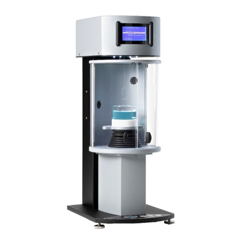
Biolin Scientific Theta User manual

Theta
Installation manual –OneAttension
Optical Tensiometer
Revision 1.7

[ Attension | KSV NIMA |Q-Sense |Sophion ]
2
Table of Contents
1. Introduction .............................................................................. 3
1.1 Features of the Theta ..................................................................... 3
1.2 Equipment overview....................................................................... 4
2. Mechanical installation .............................................................. 5
2.1 Unpacking ..................................................................................... 5
2.2 Positioning of the instrument and components ............................. 5
2.3 Connecting cables .........................................................................6
2.4 Firewire connectivity information.................................................. 6
3. OneAttension software installation ............................................ 8
3.1 Computer requirements ................................................................. 8
3.2 Software Installation with Gigabit Ethernet cameras ..................... 8
3.3 Software Installation with FireWire cameras ............................... 12
4. Contact information ................................................................. 17

[ Attension | KSV NIMA |Q-Sense |Sophion ]
3
1. Introduction
This installation manual describes the detailed hardware and software installation procedure for the Theta instrument.
The modular design of the Theta enables many equipment combinations, allowing the user to configure the instrument in a way
that meets their requirements. Optional hardware modules can be purchased and easily installed at a later date.
As this manual only contains information concerned with the installation procedure, please see the Operation Manual for
information on calibration, taking measurements and data analysis.
1.1 Features of the Theta
Once installed on your computer the Theta with OneAttension software will offer the following:
Sessile drop contact angle measurements
Dynamic contact angle measurements
Surface free energy calculations
Surface and interfacial tension measurements by pendant drop analysis
Pulsating-drop measurements for dilatational interfacial rheology studies *
Ultra-fast imaging (up to 2315 fps) e.g. of rapid droplet spreading and absorption into samples*
Picoliter sized droplet dispensing and high-zoom optics for characterization of extremely small or irregularly shaped
samples*.
Automated multi-liquid dispensing, droplet placement, sample -stage movement, instrument tilting (for advancing and
receding contact angles) and image capture & analysis for fully automated experiment control*.
Topography measurements for enhanced contact angle measurement results for rough surfaces*.
*Requires additional optional hardware module.
The latest range of additional modules can be viewed in www.biolinscientific.com/attension

[ Attension | KSV NIMA |Q-Sense |Sophion ]
4
1.2 Equipment overview
The basic setup of the operational Theta is shown below.
Figure 1.1. Physical features of a basic Theta.
1) Stage level adjustment
10) Manual dispenser adjustment
2) Stage height adjustment
11) Syringe clamp
3) Stage height lock
12) LED light source
4) Stage linear adjustment
13) Sample stage
5) Stage rail lock
14) Camera lens focus adjustment
6) Stage lateral adjustment
15) Camera lens zoom adjustment
7) Syringe lateral adjustment
16) Level adjustment feet
8) Liquid dispense holder
17) Camera rail lock
9) Syringe height adjustment

[ Attension | KSV NIMA |Q-Sense |Sophion ]
5
2. Mechanical installation
2.1 Unpacking
The Theta is delivered in one crate. The crate should be opened carefully and checked to see that it contains:
Theta instrument consisting of base with four adjustable feet, interface unit (which houses the one-touch dispenser
and LED light source) and camera stage.
Sample stage mounting with thumb screw
Power cable
Necessary communication cables
Manual dispensing syringe
Calibration ball and magnet
Bubble leveling disk.
DVD with software, license file (.xml) and manuals
As well as any optional items, which may include for example:
Automatic single/multi liquid dispenser
Motorized dispenser movement module
Motorized x/y-stage
Tilting cradle
Interconnect cables for additional modules
Sample chambers/cuvettes
2.2 Positioning of the instrument and components
The instrument should be placed on a vibration free table in an area where local air currents are at a minimum. Unwrap all
plastic wrapping carefully, taking care not to scratch the components if you cut through the wrapping with a knife. Place the
bubble leveling disk on the instrument base and adjust the leveling feet until the bubble sits in the central marked circle.
You are then required to align all components in the optical path and to give the sample stage large freedom of movement from
its mounted position by following the instructions below.
Place the sample stage mounting mechanism on the central rail of the instrument base. Use the x and y-position adjustment
screws (#4 and #6 in Figure 1.1) to adjust the sample stage x and y positions so that the sample stage is positioned in the
centre of the available travel range in both directions. With the manual syringe dispenser in place, adjust the horizontal position
of the one-touch dispenser so that the syringe tip appears near to the centre of the LED light source (when viewed from the
camera end of the instrument). Adjust the vertical position of the syringe tip either by loosening the syringe clamp, coarsely
adjusting position then retightening the syringe clamp or make fine adjustments using the syringe height adjustment screw (#9 in
Figure 1.1). Position the whole of the sample stage mounting mechanism under the syringe tip so that the centre of the square
sample stage is positioned centrally beneath the syringe tip. Do this by sliding the sample stage mounting mechanism along the
rail while the stage rail lock screw (#5 in Figure 1.1) is loose. Once in position, firmly tighten the stage rail lock screw.
Exact positioning of the camera stage along the rail is user-application specific and depends on the required zoom and focus
settings of the camera. This part of the setup is only possible once the software has been installed and is explained in the user
manual.
All the additional modules operate with simple plug and play installation, therefore the plug in instructions are included in the
user manual together with the operating instructions.

[ Attension | KSV NIMA |Q-Sense |Sophion ]
6
2.3 Connecting cables
Theta requires a computer with one free USB port, and either a Gigabit Ethernet port or a FireWire port depending on your
camera type. If the computer does not have a FireWire port available then the FireWire PCI card supplied should be installed
Connect the Theta's USB1 port to the computer USB port using the supplied USB cable. Connect the Theta’s Ethernet port to
your computer’s Gigabit Ethernet port or the Theta’s FW1 port to your computer FireWire port using the supplied cables.
Connect the power cable to the three-pin IEC connector beneath the power switch and plug in to the mains power supply.
2.4 Firewire connectivity information
On-board Firewire ports such as those connected to the front-panel of a desktop PC or built-in mini 4-pin ports in laptops are
often problematic and may not work correctly with the Theta camera. If during the software installation or initial software loading
phase the camera is not detected, even though the cables are connected and the instrument is turned on, then there may be a
problem with the type of Firewire port that you are trying to use.
If you are using a desktop computer it is strongly recommended that you install the supplied Firewire PCI card into an available
PCI slot on your computer motherboard. As this requires the computer housing to be opened up, it is advisable to contact your
I.T. department for this part of the installation unless you are a competent/qualified computer system builder.
If your laptop computer is not equipped with any type of Firewire port, or if the built-in port just doesn’t work, it is recommended
that you obtain and insert a suitable Firewire expansion card (PC Card or ExpressCard, depending on the laptop). The crucial
factor is the controller chip that the Firewire port is built around. Unfortunately, Firewire card manufacturers often don’t specify
what controller chips their cards use. It can be manually checked from the Device Manager, from "IEEE Bus Host Controllers".
The device name is usually in the form "[Chipset name] 1394 OHCI Compliant Host Controller". Texas Instruments and VIA
chips are known to work well.
It is also known that a laptop computer running in a lower power state, such as when unplugged from the mains and running
from batteries, may not allow successful Firewire communication with the Theta camera. Keeping the laptop computer
connected to the mains power supply may solve this class of communication problems.
When experiencing more or less random camera detection problems with Windows 7 + ImagingSource (60 FPS) camera,
switching to the legacy 1394 bus driver as follows may help (this is not needed with the high-speed (420 FPS) Basler camera,
as a special bus driver will automatically be installed for it):
1. In the Device Manager, select ‘Properties’ for the 1394 controller.
2. Select the 'Driver' page and 'Update Driver' button.
3. Select 'Browse my computer for driver software.'
4. Select 'Let me pick from a list of device drivers on my computer.'
5. Within the list of devices, you will see a device with '(Legacy).' This is the 1394 bus driver that previously shipped in
Windows. Select this device and select 'Next.'
This will install the legacy 1394 bus driver on Windows 7.
It is possible to ascertain if the camera is successfully identified by your computer by checking the Windows Control Panel/
System/ Device Manager. When connecting the Firewire cable with the instrument power turned on, an extra item should
appear in the hardware list. When the camera drivers are installed later on, the camera will be labeled correctly but for now it
may simply be labeled as a ‘generic 1394 camera’. If after software installation the camera is still only labeled as a ‘generic 1394
camera’, instead of being correctly identified as an ‘Imaging Source’ or ‘Basler’ (high-speed) camera, then there may have been
a problem with driver installation. Even if everything seems to be all right in the Device Manager, it’s possible that OneAttension
can’t properly communicate with the camera. It could behave as the camera didn’t exist at all, or a message ”Camera found, but
initialization failed” may pop up. If the usual restart / reboot / reinstall attempts or the “Windows 7 + ImagingSource” bus driver

[ Attension | KSV NIMA |Q-Sense |Sophion ]
7
trick above don’t help, then the problem is almost certainly caused by a defunct Firewire controller. A Firewire adapter should be
installed then, as described above.

[ Attension | KSV NIMA |Q-Sense |Sophion ]
8
3. OneAttension software installation
3.1 Computer requirements
The computer attached to the Theta is required to have
Windows Vista (32 bit), Windows 7 (32 or 64 bit), Windows 8 (32 or 64 bit) or Windows 10 (32 or 64 bit, only available
for the Basic Ethernet camera and Basic FireWire camera).
During installation the user must have administrative privileges to the computer.
One free USB port.
One free Gigabit Ethernet port or an IEEE 1394 FireWire port (if unavailable use the supplied PCI adapter)
depending on the camera you have in your Theta.
3.2 Software Installation with Gigabit Ethernet cameras
First, turn Theta power off. Connect the USB and Ethernet cables between Theta and the computer. Do not turn Theta power
on yet.
Insert the OneAttension installation DVD into the optical disk drive. Access the disk (typically drive D:\) and double-click on
OAsetup.exe. In case the OAsetup.exe is copied from the DVD e.g. in the computer’s desktop before installation, please note
that you need to copy also a license.xml file in the computer. The license.xml file is a unique file for each licensed
OneAttension copy.
The installation will now begin. Follow the instructions on screen.
During the installation it is extremely important to choose the correct drivers from the list of drivers:
Choose either “Theta Basic Ethernet” in case you have the basic camera that goes up to 344 fps or “Theta High Speed
Ethernet” in case you have the high speed camera that goes up to 2315 fps. If you have the 3D Topography module, choose
also the “Topography support”.
If for some reason the Windows cannot verify the publisher of the driver software, choose “Install this driver software anyway”.

[ Attension | KSV NIMA |Q-Sense |Sophion ]
9
The installer may also ask you to turn your instrument on during installation. This also applies to the optional 3D Topography
module.
Some of the drivers open a separate driver installation wizard in order to install the drivers. In this case, choose next and wait
until the drivers have been installed.
If the installer asks you to connect your video capture device, the camera cannot be detected. In this case, please check that the
instrument is on and all cables are connected.

[ Attension | KSV NIMA |Q-Sense |Sophion ]
10
Finally, choose “Finish” in order to finish the OneAttension installation.
Possible issues
In most cases, OneAttension installation goes very easily and all software components are installed automatically. However,
occasionally the drivers won’t install properly.
Basic Gigabit Ethernet camera
In some cases, the IP address for the camera has to be set manually. If you installed OneAttension with the “Theta Basic
Ethernet” drivers and OneAttension cannot locate the camera, please try the following actions:
Open “pylon IP Configurator” program in your computer. The program should locate your camera. Choose your camera and
write the following IP addresses to the Static IP cells:
IP Address: 169.254.1.0

[ Attension | KSV NIMA |Q-Sense |Sophion ]
11
Subnet Mask: 255.255.0.0
Gateway: 0.0.0.0
Click the Refresh. The IP addresses have now been updated and the camera should be located by OneAttension.
High speed Gigabit Ethernet camera
High speed Gigabit Ethernet camera drivers cannot be installed, if they already exist in the computer. However, there might
sometimes be a need to install the drivers again. In this case, the old drivers need to be removed first.
Go to Start Control Panel Programs Programs and Features. You will see a list of all installed software. Go to JAI SDK
and uninstall it. Windows will ask you to restart your computer, but do not do this yet.
Then go to the folder where you have installed your OneAttension. By default the path is
C:\Attension\OneAttension\bin\windows\cameras. There you will find a folder called JAI which you need to delete. After deleting,
restart your computer so that the changes will be taken into effect.
After the computer has been restarted, you can install the high speed camera drivers again normally.

[ Attension | KSV NIMA |Q-Sense |Sophion ]
12
3.3 Software Installation with FireWire cameras
First, turn Theta power off. Connect the USB and FireWire cables between Theta and the computer. Do not turn Theta power
on yet.
If you have the high-speed (420fps) Basler camera option and a laptop with a FireWire extension card, the FireWire extension
card must be connected to the laptop during OneAttension installation, because a special bus driver will be installed for it.
Insert the OneAttension installation DVD into the optical disk drive. Access the disk (typically drive D:\) and double-click on
OAsetup.exe. In case the OAsetup.exe is copied from the DVD e.g. in the computer’s desktop before installation, please note
that you need to copy also a license.xml file in the computer. The license.xml file is a unique file for each licensed
OneAttension copy.
The installation will now begin and the following series of pop-ups will appear on screen.
Click Next to continue
Click I Agree to accept the terms of the license agreement

[ Attension | KSV NIMA |Q-Sense |Sophion ]
13
Select the appropriate camera drivers to install. If you have the standard-speed (60fps) ImagingSource camera check the
ImagingSource camera box. If you have the high-speed (420fps) Basler camera option check the Basler camera box.
An installation directory needs to be chosen. It is strongly recommended that you proceed with the default installation directory
as shown above. Do not install to your Program Files folder as this may cause problems when running the OneAttension
program.

[ Attension | KSV NIMA |Q-Sense |Sophion ]
14
The installation progress can be monitored with the progress bar. Please allow several minutes for this stage of the installation
to complete.
If Windows informs you that it can’t verify the publisher of the driver software, select Install this driver software anyway.
When the ImagingSource camera driver is being installed you will be asked to turn on your Theta instrument. Ensure that the
USB and FireWire cables are connected to the computer first and that the power supply is plugged in. Switch the 0/1 power
switch to the 1 position on the Theta interface panel then click OK.

[ Attension | KSV NIMA |Q-Sense |Sophion ]
15
If there is a problem detecting the camera you will see the Device Detection error message above. Please check all FireWire
cable connections and click Retry. If the software does not proceed beyond this screen click Cancel and refer to Section 2.4
FireWire connectivity information for further support.
If you are installing the Basler camera driver the installation will automatically proceed through to completion without any further
action required.
If the ImagingSource camera driver was selected a Driver Installation Wizard will start up. All the connected & detected
ImagingSource cameras will be listed. Usually only the Theta ImagingSource camera will be listed (but named as shown above).
Ensure that the tickbox is checked and click Next.
The progress of the ImagingSource driver installation will be indicated by the progress bar.

[ Attension | KSV NIMA |Q-Sense |Sophion ]
16
When the ImagingSource camera driver installation is completed you will see the above screen. Click Finish.
Following camera driver installation you will be informed that OneAttension has been installed on your computer. Click Finish to
complete the software installation.

[ Attension | KSV NIMA |Q-Sense |Sophion ]
17
4. Contact information
If any problems arise please feel free to contact a local distributor or Attension directly.
Attension can be contacted from this address:
Attension, Biolin Scientific
Tietäjäntie 2
FI-02130 Espoo
Finland
Tel. +358-(0)9-5497 3300
Fax +358-(0)9-5497 3333
info@biolinscientific.com for sales requests
support@attension.com for service or technical support and maintenance
http://www.biolinscientific.com/attension
Local distributors are listed at our website, http://www.biolinscientific.com/attension
Table of contents
Other Biolin Scientific Laboratory Equipment manuals
Popular Laboratory Equipment manuals by other brands

Belden
Belden HIRSCHMANN RPI-P1-4PoE installation manual

Koehler
Koehler K1223 Series Operation and instruction manual

Globe Scientific
Globe Scientific GCM-12 quick start guide

Getinge
Getinge 86 SERIES Technical manual

CORNING
CORNING Everon 6000 user manual

Biocomp
Biocomp GRADIENT MASTER 108 operating manual