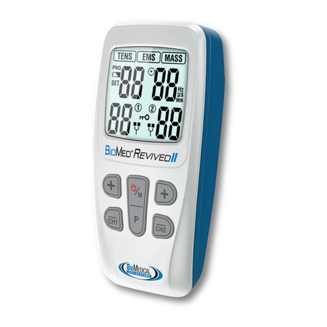
BioMedical Life Systems, Inc. BioStim NMS2 User manual

0
NOTES
_______________________
_______________________
_______________________
_______________________
_______________________
_______________________
_______________________
_______________________
_______________________
_______________________
_______________________
_______________________
_______________________
_______________________
_______________________
_______________________
Copyright © 2006 BioMedical Life Systems, Inc.
All rights reserved
Instructions
Neuromuscular Stimulator
BioStim®NMS2
BioMedical Life Systems,Inc.
Bio Stim
®
NMS
2
Manufactured and Distributed by :

1
Contents
1. Introduction to the BioStim® NMS²…………………………………....…4
1.1 Device Overview
1.2 Indications for Use
2. Patient Safety Information.......................................................5
2.1 Precautions
2.2 Caution
2.3 Adverse Reactions
2.4 Contraindications
3. Technical Data........................................................................7
4. Modes Explained (Factory Settings) …..……………………..……..……9
4.1 Programmable Mode Starting Parameters
4.2 Pre-Set Therapy Mode Parameters
5. Batteries…………………………………………………………………….………11
6. Electrodes and Lead Wires……………………………………………….....12
6.1 Connect Electrodes and Leadwires
7. Graphic Symbol Definitions……………………………………………..…..13
7.1 BioStim® NMS² Button Descriptions
8. Programming Instructions……………………………………………………14
8.1 Toggling through Modes
8.2 Defining Timing Options; Ramp Time, On Time, Off
Time & Delay.
8.3 Changing Timing Options; Ramp Time, On Time, Off
Time & Delay.
8.4 Changing PR(Hz), PW (US) and Waveform Values
8.5 Patient Timer
8.6 Patient Lock
8.7 Patient Compliance Meter
8.8 Restoring Factory Settings

2
Contents
9. Programmable Modes Explained…………………………………………22
9.1 Constant Stimulation (CONST)
9.2 Setting the CONST mode
9.3 Cycled Stimulation
9.4 Setting the Cycled Mode
9.5 Reciprocal Stimulation (RECIPR)
9.6 Setting the Reciprocal (RECIPR) Mode
10. Using Therapy Modes 1-8…………………………….……………………27
11. Malfunctions........................................................................28
12. Safety and Technical Checks…………………………………..………….29
13. Maintenance and Care..........................................................29
14. Warranty.............................................................................29
BIOSTIM NMS2 INSTRUCTION MANUAL
Please consult your physician or prescribing practitioner for specific
instructions regarding the settings of your device. Please read and
understand this manual before beginning to use the BioStim® NMS².

3

4
1. Introduction BioStim® NMS2
1.1 Device Overview
The BioStim NMS2 is a portable electrotherapy device which sends
a gentle electrical current to underlying nerves and muscles via
electrodes applied to the skin. The device is a NeuroMuscular
Stimulator (NMS) used to stimulate muscles for an array of
conditions.
1.2 Indications for Use
NeuroMuscular Stimulation (NMS), also commonly referred to as
Electrical Muscle Stimulation (EMS) is the use of electrical
stimulation on muscle groups to contract and re-educate muscles.
Some of the uses of NMS are as follows:
1) The Prevention or Retardation of Muscle Disuse Atrophy: Muscle
disuse atrophy is a reduction in muscle tone and size due to
prolonged impairment or joint immobility from surgery or injury. The
use of NMS to contract the muscles assists in prevention of disuse
atrophy.
2) Relaxation of Muscle Spasms: Muscle spasms often occur in areas
of localized pain and tenderness. Stimulation is used to fatigue the
spasmodic muscle.
3) Maintaining and Increasing Range of Motion
4) Muscle Reeducation
5) Increasing Local Blood Circulation: Rhythmic muscle contraction
helps improve local blood circulation.
6) Immediate Postsurgical Stimulation of Calf Muscles to Prevent
Venous Thrombosis. The use of NMS or EMS to increase local blood
circulation assists in the prevention of venous thrombosis.

5
2. Introduction BioStim® NMS2
2.1 Precautions should be taken when stimulation is used;
• After recent surgical procedure where muscle contraction may
disrupt the healing process.
• After an acute trauma or fracture where there is a tendency to
hemorrhage.
• Over the menstruating uterus.
• Where the sensory nerve damage has caused the loss of normal
skin sensation.
EQUIPMENT not suitable for use in the presence of a FLAMMABLE
ANESTHETIC MIXTURE WITH AIR or WITH OXYGEN OR NITROUS
OXIDE.
2.2 Caution:
NMS or EMS Devices should only be used under medical supervision
for adjunctive therapy in the treatment of medical diseases and
conditions. Dependent upon government regulation, this device
may or may not require a medical prescription. Federal law (USA)
restricts the sale by, or on the order of, a physician so licensed by
the State. Keep out of reach of children.
2.3 Adverse Reactions:
Some patients may experience skin irritation or hypersensitivity due
to electrical stimulation or electrically conductive medium. The
irritation can usually be reduced by using an alternative conductive
medium, or alternate electrode placement. Improper use of
stimulation may result in skin irritation and burns beneath the
electrodes. Electrode placement and stimulation settings should be
based on the guidance of the prescribing practitioner.
2.5 Contraindications:
1) Powered muscle stimulators should not be used on patients with
cardiac demand pacemakers.
2) NMS or EMS devices should not be applied over, or in proximity
to, cancerous lesions.

6
3) NMS devices should not be used while driving, operating
machinery or during any other activity in which involuntary muscle
contraction may put the user at undue risk of injury.
4)Stimulation should not be applied over the carotid sinus. Severe
spasm of the laryngeal and/or pharyngeal muscles may occur when
electrodes are placed over the neck or mouth. (These contractions
may be strong enough to close the airway or cause difficulty in
breathing.)
5)Stimulation should not be applied transcerebrally (through the
head).
6) Adequate precaution should be taken when treating patients with
suspected heart problems or epilepsy. Caution should be exercised
in the transthoracic application of EMS devices so that the
introduction of electrical current into the heart does not cause
arrhythmias. Stimulation should not be applied over swollen,
infected, or inflamed areas or skin eruptions, e.g., phlebitis,
thrombophlebitis, varicose veins, etc. Persistent use of stimulation
in the presence of skin irritation may be injurious.
7)The safety of electrical stimulation for use during pregnancy has
not been established.
8)The long-term effects of chronic electrical stimulation are
unknown.
9) EMS devices should be kept out of the reach of children.
10) Simultaneous connection to RF surgery equipment can cause a
burn.
11) Operation near (e.g. 1m) short wave or micro wave therapy
equipment can change the output values of the stimulator.
12) This equipment may be affected by electromagnetic
interference. Also, other electrical equipment in close vicinity may
be affected by the BioStim NMS. If such effects are suspected either
switch off the offending equipment or increase the distance
between the affected equipment and that suspected of causing the
interference or shorten connecting leads.

7
3. Technical Data
Accessoires
2 Leadwires (4 pins)
4 electrodes (pads)
1 Instruction Booklet
4 AA Batteries
1 Carry Pouch
Only use accessories, electrodes, leadwires and batteries
approved by BioMedical Life Systems, Inc.
Size
3.9"x2.6"x1.3" (99mmx65mmx33mm)
Weight
8 oz (226g)
Power supply
4 AA Batteries, type LR6
Channels
Dual
Waveform
Symmetrical, biphasic square (SYM) and
Asymmetrical, biphasic square (ASYM)
Pulse Rate
Adjustable 1 - 120 Hz (Hertz), pulses/sec
Pulse Width
Adjustable 50 - 400 μS (microseconds)
Ramp On
0-99 seconds
Ramp Off
0-99 seconds
On Time
0-99 seconds
Off Time
0-99 seconds
Delay
0-99 seconds
Patient Timer
0-99 minutes
Modes
1.Constant 2. Cycled 3. Reciprocal
(adjustable)
Therapies
8 Preprogrammed (fixed)
Intensity/Output
Voltage
Continuously adjustable from 0-120mA peak
(0-60V) +/- 10%
Tolerance
All parameters +/- 2% unless otherwise noted
Data recorded across a 500 OHM load resistance

8
Guidance and Manufacturer’s declaration-
electromagnetic emissions
This device is intended for use in the electromagnetic
environment specified below. The customer or the user
should assure that it is used in such an environment.
Emissions Test
Compliance
Electromagnetic
environment-
guidance
RF emissions
CISPR11
Group 1
This device uses RF
energy only for its
internal function.
Therefore, its RF
emissions are very low
and are not likely to
cause any interference
in nearby electronic
equipment.
RF Emission
CISPR 11
Class B
This device is suitable
for use in all
establishments,
including domestic
establishments
and those directly
connected to the public
low-voltage power
supply network that
supplies buildings for
domestic purposes.
Harmonic
emissions IEC
61000-3-2
Not
applicable
Voltage
fluctuations
Flicker emissions
IEC 61000-3-3
Complies
This device was not tested for IMMUNITY to ELECTROMAGNETIC
DISTURBANCES.

9
4. Modes Explained
4.1 Programmable Mode Starting Parameters:
There are 3 Programmable Modes on the BioStim® NMS
1. Constant; 2 Cycled; 3 Reciprocal
• Each of the three programmable modes has starting parameters,
however the parameters may be adjusted by the user.
• Programmable settings may be customized and saved.
(All times measured in seconds unless otherwise specified.)
Mode
Waveform Parameters
(PR= Pulse Rate; PW=Pulse
Width)
Timing Options
1. Constant
(CONST)
Asymmetrical Biphasic
Square
N/A
PR
120Hz
PW
50μS
Use of the Constant Mode or a Pulse Rate greater than 60Hz with a
symmetrical biphasic square waveform should be used for the
relaxation of muscle spasms only. Use of constant stimulation
and/or rates above the normal physiological range (e.g., greater
than 60Hz) could lead to rapid onset of muscle fatigue, making the
device less effective in producing repeated forceful muscle
contractions.
2. Cycled
Symmetrical Biphasic Wave
Ramp
On/Off
2/2
PR
35Hz
PW
300μS
On Time
10
Off Time
20
In the CYCLED mode; both Channel 1 and Channel 2 cycle
simultaneously.
3. Reciprocal
(RECIPR)
Symmetrical Biphasic Wave
Ramp
On/Off
2/2
PR
35Hz
PW
300μS
On Time
10
Off Time
20
In the RECIPR mode, Channel 1 and Channel 2 alternate; (Channel
1 is on while Channel 2 is off).

10
4.2 Pre-Set Therapy Mode Parameters:
There are 8 Pre-Set Therapies in the BioStim® NMS².
Note: Settings in the following THERAPY modes are FIXED and
cannot be changed. If custom settings are needed, please see
Programmable Modes Explained; (Section 9)
Therapy
Stimulation Pattern;
(Const, Cycled or Reciprocal)
Timing Options
(In Seconds)
Therapy
1
Cycled
Ramp On/Off
2/2
Symmetrical Biphasic Wave
On Time
10
PR
35Hz
PW
300μS
Off Time
20
Therapy
2
Cycled
Ramp On/Off
2/2
Asymmetrical Biphasic Wave
On Time
10
PR
35Hz
PW
400μS
Off Time
20
Therapy
3
Cycled
Ramp On/Off
2/2
Symmetrical Biphasic Wave
On Time
10
PR
50Hz
PW
180μS
Off Time
20
Therapy
4
Cycled
Ramp On/Off
2/2
Symmetrical Biphasic Wave
On Time
5
PR
20Hz
PW
250μS
Off Time
10
Therapy
5
Constant
Ramp On/Off
0
Symmetrical Biphasic Wave
On Time
0
PR
10Hz
PW
50μS
Off Time
0

11
Therapy
6
Constant
Ramp On/Off
0
Asymmetrical Biphasic Wave
On Time
0
PR
10Hz
PW
200μS
Off Time
0
Therapy
7
Cycled
Ramp On/Off
1/0
Symmetrical Biphasic Wave
On Time
5
PR
35Hz
PW
400μS
Off Time
5
Therapy
Cycled
Ramp On/Off
2/2
Symmetrical Biphasic Wave
On Time
10
PR
35Hz
PW
50μS
Off Time
20
5. Batteries
5.1 Batteries
In order to maintain the functional operation of the BioStim NMS²,
the batteries will have to be changed periodically. The device is
supplied with 4 AA Alkaline batteries. When batteries are running
low, a battery image will appear and flash on the bottom right
hand corner of the LCD display screen. When this image appears,
the batteries should be changed to ensure maximum performance.
If you have saved programs into the device, they will remain
stored even when the batteries are changed.
To insert batteries:
• Before opening the battery compartment, check sure that the
device is switched off.
• Flip open the battery compartment cover.
• Remove the batteries from the compartment. Gently insert the
new batteries by matching the +/- end of each battery with the +/-
symbol found inside the battery compartment.
• Flip the battery cover to the closed position.
• Remove the batteries if you do not plan to use the device for long
periods of time, otherwise leakage and damage to the device may
occur.
• Dispose of batteries in a proper manner.

12
6. Electrodes and Leadwires
• The "leadwires" are the 48" wires provided with your device.
• The "electrodes" are the four adhesive pads provided with your
device.
• The leadwires and electrodes should be replaced periodically.
They are consumable supplies and are not covered under the
device warranty.
• Only use accessories approved by BioMedical Life Systems, Inc.
Use of non-approved accessories may affect the performance of
the device, cause injury and void the device warranty.
• The electrodes are disposable and should be replaced routinely
when they start to lose their adhesive properties.
• Replacement electrodes and leadwires should be reordered
through the dealer who supplied the device.
6.1 Connect electrodes and lead wires
1) Make sure the device is turned off, if the device is on, press the
button labeled "On/Off" one time until the LCD display is blank.
2) Insert the leadwires into the sockets in the top of the BioStim
NMS2 device marked "Ch1 and/or Ch2". If only two electrodes are
needed, you may insert the wire into only one Ch.
3) Attach the electrodes to the leadwires following the instructions
on the electrode packaging. At least 2 electrodes from the same
channel must be placed on the body for stimulation to begin.
4) Check to ensure that no metal is exposed from the pin of the
leadwire where it connects to the electrode.
5) Attach the electrodes to the body per your physicians
instructions.

13
7. Graphic Symbol Definitions
0086
7.1 BioStim® NMS² Button Descriptions
Button Symbol
Button Function
1
ON/OFF
2/3
AMPLITUDE
CONTROL
4/9
INCREASE VALUE/
DECREASE VALUE
5
MODE SELECT
6
ENTER
7
SETTING
INFORMATION KEY
8
PULSE
RATE/PULSE
WIDTH &
WAVEFORM
SELECT
10
TIMER KEY
Refer to
operating
instructions
An IEC 601-1 safety
standard (type BF)
We herewith declare that the above-
mentioned product meets the
provisions of the Medical Device .

Basic Button Functions:
Button 1 "On/Off" Key: This button is used to turn the device
on or off.
Button 2 & 3 "Amplitude Control" Keys: These buttons are
used to begin or adjust the intensity flow of energy through the
lead wires to the electrodes. Button (2) controls Channel 1
amplitude and button (3) controls Channel 2 amplitude. Each
Channel's intensity is controlled independently. You may use only
one channel at a time or both simultaneously.
Button 4 & 9 "Increase Value/Decrease Value" Keys: These keys
are used to increase or decrease numeric values of the parameters
such as pulse rate, pulse width, waveform and timing options
(RAMP TIME, ON TIME, OFF TIME & DELAY).
Button 5 "Mode Select" Key: This key is used to change the mode
on the device.
Button 6 "Enter": This key is used to accept a value.
Button 7 "Setting Information Key": This key is used to view the
timing options (RAMP TIME, ON TIME, OFF TIME & DELAY) of a
Mode or Therapy without changing the values.
Button 8 "Pulse Rate/Pulse Width & Waveform Select" Key: This
key is used to select the Pulse Rate, Pulse Width, or Waveform in
order to change the values.
Button 10 "Timer" Key: This key is used to select the Patient
Timer in order to set the value.
8. Programming Instructions
The BioStim NMS2 features three adjustable Modes; (CONSTANT,
CYCLED and RECIPROCAL (RECIPR) and eight preset fixed
therapies (THERAPY 1-8) comprised of commonly used Constant,
Cycled or Reciprocal settings. If none of the eight preset therapies
meet the user's needs, the three programmable modes may be
used to create and store custom programs. The BioStim® NMS2
has a timer, Patient Lock and Patient Compliance Monitoring
functions.
14

15
8.1 Toggling through the Modes:
1) Turn the device on or (1) "On/Off" Key
2) Choose a Mode by pressing the "Mode" Key (5)
repeatedly until the mode or therapy you wish to use is displayed
on the screen.
The following diagram demonstrates the order in which pressing
the "Mode" Key (5) scrolls through the device modes.
(5)
Once the desired mode is displayed on the screen you may begin
stimulation by pressing the (2) or (3) keys. The (2)
key controls the amplitude of Channel 1 and the (3) key
controls the amplitude of Channel 2.
In CONST, CYCLED and RECIPR modes you may adjust the
settings before beginning stimulation.
8.2 Defining Timing Options; RAMP TIME, ON TIME OF
TIME & DELAY
The timing options include the Ramp On, Ramp Off, On Time, Off
Time & Delay and can be modified in the Cycled or RECIPR modes
(only). The device will hold the custom settings until changed or
until the device is reset to factory settings.
Cycled
Therapy
1
Recipr
Therapy
2
Therapy
7
Therapy
8
Therapy
6
Therapy
5
Therapy
4
Therapy
3
CONST

16
RAMP ON: Is the amount of time in seconds the device itensity
ramps up from the OFF Time to the maximum intensity of the ON
Time in each cycle.
RAMP OFF: Is the amount of time in seconds the device intensity
ramps down from the ON Time to the OFF Time in each cycle.
Special Notes Regarding RAMP ON/OFF Times
•In the BioStim® NMS2the RAMP ON can be different from the
RAMP OFF value in the cycle.
•The RAMP ON and RAMP OFF values set to both Channel 1
and Channel 2. ON TIME: The total amount of time seconds in
each cycle that the device intensity is on, including the ramp
times.
Special Notes Regarding ON TIME:
•Once the RAMP ON and RAMP OFF values have been set, the
device will not allow the user to set a ON TIME value lesser than
the sum of the RAMP ON and RAMP OFF values, as the ON
TIME is the total time the device intensity is on in the cycle,
including the ramp times.
•Note: The ON TIME value is set independently for Channel 1
and Channel 2 and may be a different value for Channel 1 than
Channel 2.
•If different ON TIME values are set for Channel 1 and Channel 2
in a CYCLED program, the difference between the Channel 1
and Channel 2 ON TIME will be automatically added or
subtracted from the Channel 2 OFF TIME as the total cycle
times for Channel 1 and Channel 2 need to be the same in the
CYCLED mode. In the RECIPR mode, the total cycle time does
not need to be the same, therefore, the user may set different
ON TIME values for Channel 1 and Channel 2 without the
device deducting the difference from the OFF TIME of Channel
2.
OFF TIME: The amount of time in seconds that the device
intensity is off in each cycle.

17
DELAY: The amount of time in seconds between the begininning
of Channel 1 cycle and beginning 2 cycle. (DELAY is available in
the CYCLED mode only). The DELAY can be adjusted from 1-99
seconds.
Note: If a "DELAY" value is set in the CYCLED mode, the number
of seconds set for the DELAY will be automatically deducted from
the OFF TIME of Channel 2, as both Channel 1 and Channel 2 total
cycle times must be the same. The following is an example of a
Cycled Program with a DELAY time of 5 seconds.
Channel 1
Channel 2
Ramp on
2.0 sec.
2.0 sec.
Ramp off
2.0 sec.
2.0 sec.
On time
20 sec.
10 sec.
Off time
10 sec.
15 sec.
Delay
N/A
5 sec.
TOTAL
35 sec.
35 sec.
8.3: Changing Timing Options; RAMP TIME, ON TIME OFF
TIME & DELAY
Step 1: Turn the device OFF and then back ON by pressing the
"ON/OFF" Key (1)
Step 2: Press the "Mode Key" (5) repeatedly until either
"Cycled or "RECIPR" appear on the screen.
CH 1
CH 2
DELAY
ON TIME
ON TIME
OFF TIME
OFF TIME

18
Step 3: Press the +(4) key until the numeric value for
RAMP ON flashes on the screen.
Step 4: Increase or decrease the value of the flashing number by
pressing the +(4) and/or -(9) keys.
Step 5: Press the "Enter" (6) key to accept the set value.
Device then moves to the next adjustable timing option
displayed in the diagram (below), beginning with RAMP ON.
Step 6: Continue moving through each value, changing the value
by pressing the +(4) Aand -(9) keys and/or
accepting the value by pressing the "Enter" Key (6) until
there are no blinking values.
Step 7: (Optional) To review the timing option settings without
changing them, use the "Info" Key (7) to scroll through the
settings.
Step 8: You may begin stimulation by pressing the (2) and/or (3)
keys.
Note: The stimulation cannot begin if any value on the LCD screen
is blinking. If a value is blinking on the screen, press the "Enter"
Key (6) until there are no blinking values.
(6)
8.4 Changing PR (Hz), PW (µS) and Waveform Values
To change the "PR" (Pulse Rate Value, measured in Hz), PW
(Pulse Width (measured in µS) or Waveform (SYM = Symmetri cal
Biphasic or ASYM = Asymmetrical Biphasic Waveform)
RAMP
ON
RAMP
OFF
CH 1
OFF
Delay
CH 2
OFF
CH 2
ON

19
Step 1: Turn the device OFF and then back ON by pressing the
"ON/OFF Key" (1)
Step 2: Press the "PR/PW" (8) key repeatedly until the
parameter you desire to change is flashing
Step 3: Use the +(4) and -(9) keys to
increase/de crease or change the value.
Step 4: You must press the "Enter" key (6) to accept the
value. To change another parameter, repeat steps 2-4.
Note: The stimulation cannot begin if any value on the LCD
screen is blinking. If a value is blinking on the screen, press the
"Enter" Key (6) until there are no blinking values.
(8) (8)
E(6) (4/9)
8.5 Patient Timer
The BioStim NMS2device has a patient Timer feature. When the
timer is enabled, the device counts down in minutes. The device
shuts off when the time runs out. If the timer is not set, the device
will continue to run until the "ON/OFF" key (1) is pressed, or if
the device is idol (with no intensity settings) for 7 consecutive
minutes.
Step 1: If any values are blinking on the screen press the "Enter
Key" (6) until all values are accepted and nothing is blinking
or turn the device OFF and back ON by pressing the "ON/OFF" Key
(1)
PW (μS)
PR (Hz)
Table of contents
Other BioMedical Life Systems, Inc. Medical Equipment manuals
