DentalEZ NuSimplicity User manual
NuSimplicityTM Chair
User Manual

i
www.DentalEZ.com 866-DTE-INFO
i
DentalEZ®Equipment
PN: 2717-256E
Table of Contents
Section I Introduction
Product Overview ............................................... 1
Chair Features ....................................................2
Dimensions ........................................................ 3
Range of Motion ................................................ 4
Specications .................................................... 5
Classications ................................................... 6
Explanation of Symbols & Signs ...................... 6
Safety Precautions.............................................7
Section II Preinstallation
Packaging .......................................................... 9
Chair Placement ............................................... 10
Section III Installation
Left and Right Spring Covers............................11
Delivery Units.................................................... 12
Wired Touchpad Control .................................. 12
Wired Foot Control............................................ 13
Wireless Controls.............................................. 13
Air Glide (Optional)............................................ 15
Upholstery......................................................... 16
Installation Checklist........................................18
Section IV Operation
Base Lowering Safety Switch.......................... 19
Chair Rotation................................................... 19
Armrests .......................................................... 20
Standard Fixed Headrest................................ 20
Double Articulating Headrest (Optional) ........ 21
Air Glide (Optional)............................................ 21
Manual Chair Positioning ................................ 22
Automatic Chair Positioning........................... 23
Programming Chair Travel Limits .................. 24
Control Valve Speed Adjustment ................... 25
Section V Care
Cleaning ............................................................27
Disinfecting...................................................... 29
Section VI User Service Information
Service Instruction ........................................... 31
Disposal of Equipment..................................... 31
Section VII Parts Lists/Diagrams
Hydraulic .......................................................... 33
Electrical .......................................................... 33
Mechanical....................................................... 33
Controls............................................................ 33
Exterior Components...................................... 33
Upholstery........................................................ 33
EMC Information.............................................. 35
Limited Warranty............................................. 37

www.DentalEZ.com 866-DTE-INFO
ii
NuSimplicityTM Chair
PN: 2717-256E

1
www.DentalEZ.com 866-DTE-INFO
1
DentalEZ®Equipment
PN: 2717-256E
Section I Introduction
Before starting installation procedures, review
the illustration to become familiar with the
components of the NuSimplicity Chair (Figure 1).
After the NuSimplicity Chair is installed, review
the features, operation procedures, and care
guidelines with the doctor’s sta.
Leave this manual in the doctor’s oice.
Product Overview
• Installation by an authorized DentalEZ
dealer service technician is recommended.
• For any questions about an order, please
contact a DentalEZ Equipment customer
service representative at 866-DTE-INFO.
NOTICE
Figure 1. Main components of the NuSimplicity dental chair
Headrest
Back
Seat
Armrest
Brake
Base (Cantilever Section)
Base (Pump) Cover
Armrest
Base Plate
Touchpad
Foot Control
(Wired or Wireless)
This manual contains the installation, operation
and care instructions and user service information
for the DentalEZ® NuSimplicity™ Chair.
The NuSimplicity Chair is intended to be used by
trained professional dental care personnel only.
The dental chair supports a patient in a reclined,
seated position. Operators will be positioned
around the patient’s head as required for
optimum access for the specic procedure being
performed.
The NuSimplicity Chair is designed to provide
trouble-free service when installed, operated and
cared for according to the procedures set forth in
this manual.
To ensure proper installation, carefully read
all the instructions contained in this manual,
paying close attention to all warnings,
cautions and notes.

www.DentalEZ.com 866-DTE-INFO
2
NuSimplicityTM Chair
PN: 2717-256E
Chair Features
The NuSimplicity Chair oers simple design, coupled with superior height adjustment range and lift
capacity. Superior ergonomic design minimizes twisting and reaching. In order to achieve the most
eicient use in the operatory and understand what the NuSimplicity Chair oers, here is a compilation
of some of those features and benets.
Standard Features
• A 60-degree rotation allows optimal positioning for every procedure.
• Adjustable height range suitable for stand-up and sit-down dentistry.
• Thin tapered back for better access to the oral cavity.
• Slim 12¾" width at top of chair back.
• Easily visible illuminated ON indicator.
• Slim, wider cantilever for ease of internal umbilical.
• Integrated touchpad controls located on both sides of upper backrest provide easy and rapid patient
positioning.
• Simple chair controls include auto return, last position, three presets and manual settings.
• Seamless or seamed upholstery.
• Fixed headrest.
• Base safety switch feature ensures nothing gets caught underneath the base as it lowers.
Optional Features
• Multiple headrest options available.
• Wired or wireless foot control for
patient positioning.
• Wireless remote touchpad control
eliminates clutter from touchpad and
foot controls.
• Exclusive air glide for ease of
movement and repositioning of the
chair in the operatory.
• IV arm board, IV bag stand and body
straps for oral surgery.
• USB port for today’s technology needs.
Section I Introduction
3
www.DentalEZ.com 866-DTE-INFO
3
DentalEZ®Equipment
PN: 2717-256E
Section I Introduction
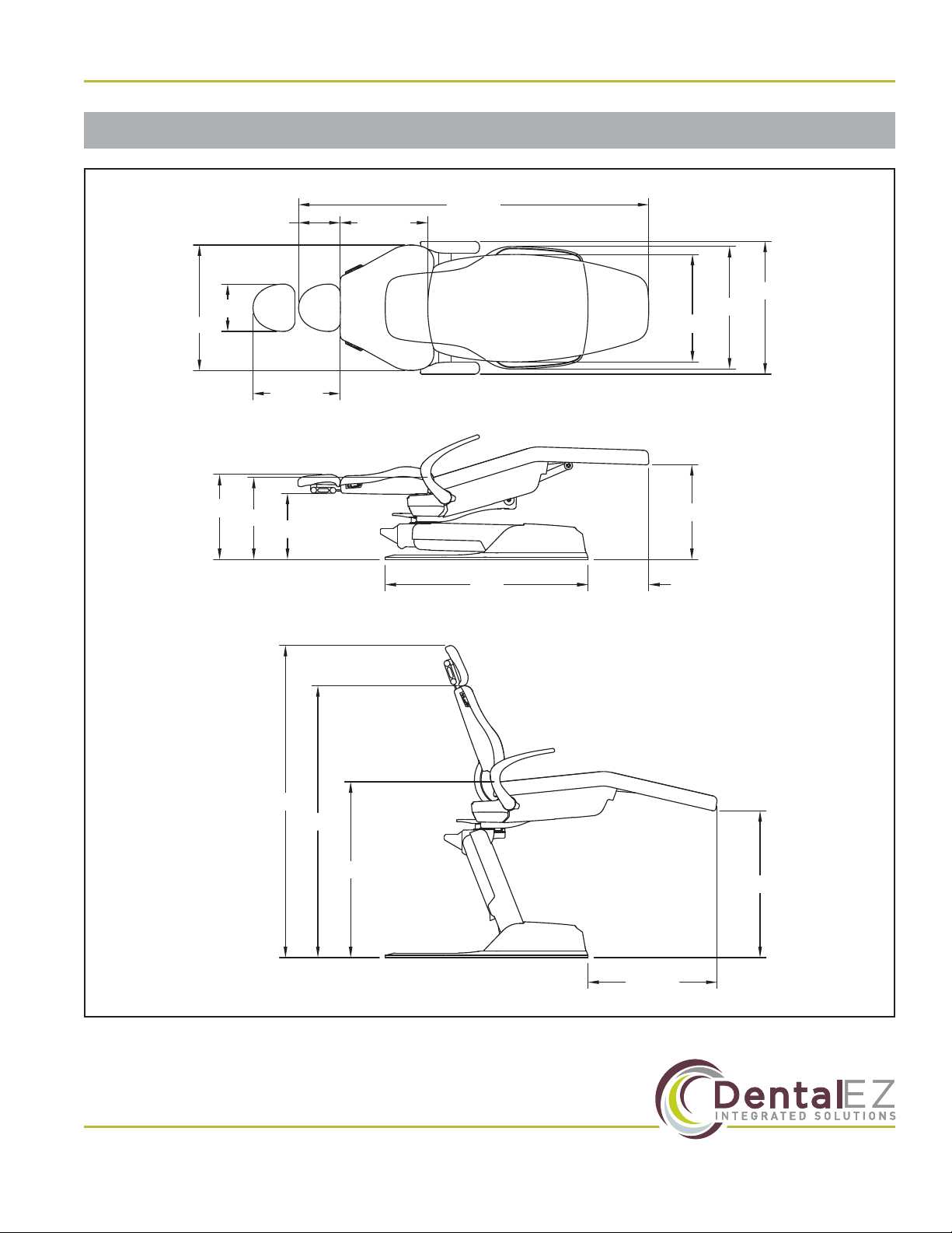
Dimensions
Figure 2. Top view, side reclining and side upright dimensions for the NuSimplicity dental chair
26¾"
30½"
36½"
56¼"
64¾"
42"
13¾"
17"
17½" 19½"
12½"
72½"
18⅛"
8⅝"
26"
9⅞"
18⅛"
22¼"
25¼"
27½"
www.DentalEZ.com 866-DTE-INFO
4
NuSimplicityTM Chair
PN: 2717-256E
Section I Introduction
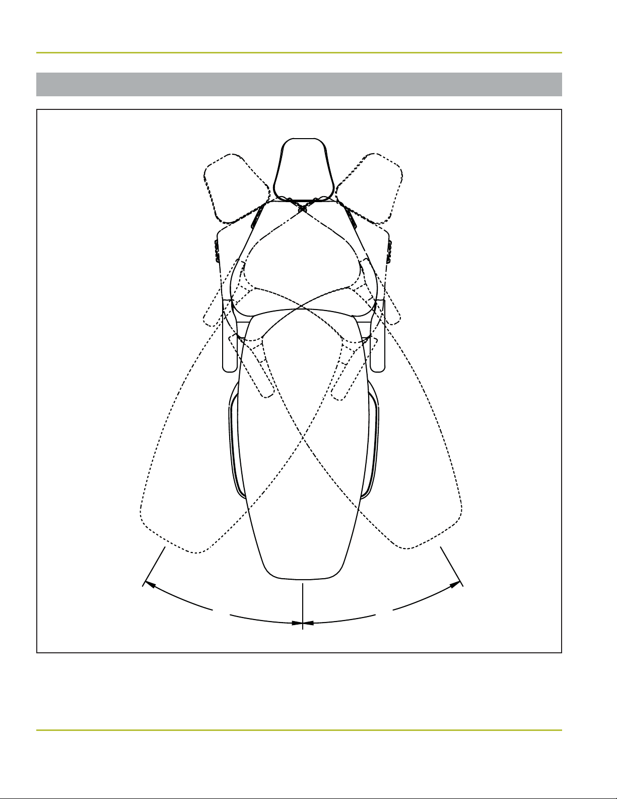
Range of Motion
Figure 3. Range of motion for the NuSimplicity dental chair
30°
30°

5
www.DentalEZ.com 866-DTE-INFO
5
DentalEZ®Equipment
PN: 2717-256E
Power Supply
• 115V AC, 60 Hz, as applicable
• 220V AC, 50/60 Hz, as applicable
• 15-Amp fused branch circuit
Fuse
• F1/F4 - 8A @ 250V
• F2 - 1A @ 250V
Shipping (Package) Weight
• Chair: 425 lb. (193 kg)
• Chair/Delivery Unit/Light (typical assembly):
570 lb. (258 kg)
Empty Weight
• 300 lb. (136 kg)
Delivery System Capacity
• 125 lb. (56.6 kg)
Total Lift Capacity
• 600 lb. (272 kg)
Maximum Patient Weight
• Factory tested to lift a load of 300 lb. (136 kg)
Shipping (Package) Dimensions
• 58.5"L ×34"H ×32.5"W
Specications
Minimum Installation Space
• 10' ×10' (3 m ×3 m)
Base Plate Footprint
• 42" ×25¼" (106 cm ×64 cm)
Recommended Environmental Conditions
Transportation and Storage
• Temperature range: -20°F to 165°F
(-29°C to 74°C)
• Relative humidity range: 0% to 95%
Operation
• Temperature range: 41°F to 104°F (5°C to 40°C)
• Relative humidity range: 0% to 95%
• Atmospheric Pressure Range: 50 to 106 kPa
Indoor Use
• Altitude up to 9,842 ft (3,000 m)
• Installation Category: II
• Pollution Degree: 2
Section I Introduction
www.DentalEZ.com 866-DTE-INFO
6
NuSimplicityTM Chair
PN: 2717-256E
Section I Introduction
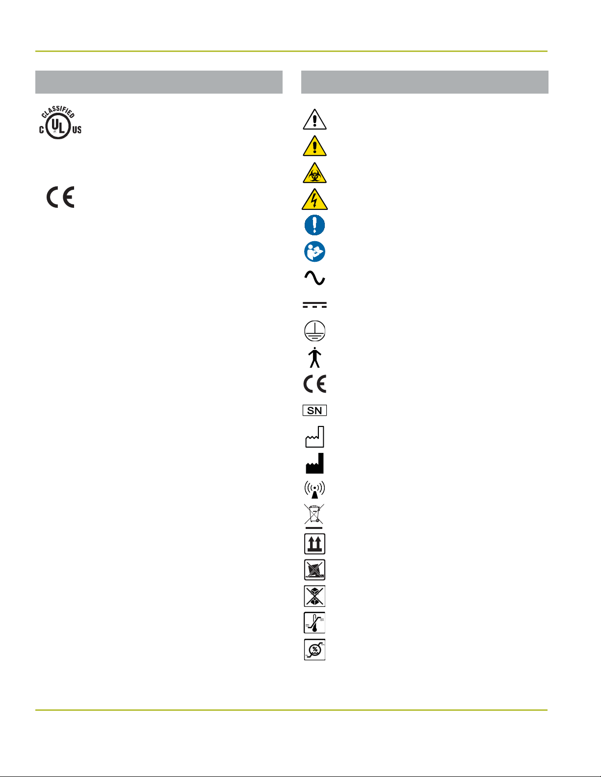
Explanation of Symbols & Signs
Classications
• Type of Protection Against Electric Shock:
Class 1 Equipment.
• Degree of Protection Against Electric Shock:
Type B Applied Parts. The upholstery is
considered an applied part.
• Flammable Gases: Equipment not suitable for
use in the presence of a ammable anesthetic
mixture with air, oxygen or nitrous oxide.
• Mode of Operation: Duty cycle – 1 minute ON,
6 minutes OFF.
Medical-General Medical Equipment
Certied as to electrical shock, re
and mechanical hazards only in
accordance with:
UL 60601-1
CAN/CSA C22.2 NO. 601.1
CAN/CSA C22.2 NO. 60601-1-08
ANSI/AAMI ES60601-1:2005
53HN
RISK
CLASS
2G
The authorized European representative is:
Dental Hygienics & Decontamination (DHD)
41 Blackwell Drive, Braintree Business Park
Braintree Essex, CM7 2PU, UK
Phone: +44 01787 877877 (ext. 200)
= Caution
= Warning
= Biohazard
= Warning - Dangerous Voltage
= General Mandatory Action
= Refer to Manual (Follow Instructions)
= Alternating Current
= Direct Current
= Protective Earth (Ground)
= Type B Applied Part
= European Certication
= Serial Number
= Manufacture Date
= Manufacturer
= Electromagnetic Radiation
= Do Not Trash
= Box Must Remain Upright
= Do Not Place Box on Unlevel Surface
= Do Not Stack Box
= Box Contents Safe Temperature Range
= Box Contents Safe Humidity Range
7
www.DentalEZ.com 866-DTE-INFO
7
DentalEZ®Equipment
PN: 2717-256E
Section I Introduction
Safety Precautions
• Before attempting to move the chair, it
must be lowered to its lowest position and
locked in place at zero degrees rotation. It
is strongly recommended that accessories,
such as lights and units, be removed before
moving.
• Rating of main circuit breakers should be
20 Amps maximum.
• To satisfy FCC RF exposure requirements
for mobile and base station transmission
devices, a separation distance of 20 cm or
more should be maintained between the
antenna of this device and persons during
the operation. To ensure compliance,
operation at closer that this distance is not
recommended. The antenna(s) used for
this transmitter must not be co-located
or operating in conjunction with any other
antenna or transmitter.
CAUTION
• Wiring schematics are provided with this
manual.
• Isolating the unit from the supply mains is
accomplished by unplugging the unit from
the power receptacle.
NOTICE
Before proceeding with electrical
installation, all wiring must be in
accordance with NEC and local electrical
codes.
To avoid the risk of electrical shock, this
equipment must only be connected to a
supply mains with protective earth.
• Do not modify the NuSimplicity Chair
without permission from DentalEZ.
• The use of ACCESSORY equipment not
complying with the equivalent safety
requirements of this equipment may lead
to a reduced level of safety of the resulting
system. Consideration relating to the
choice shall include:
• Use of the accessory in the PATIENT
VICINITY
• Evidence that the safety certication
of the ACCESSORY has been
performed in accordance to the
appropriate IEC 60601-1 harmonized
standard.
• The plug cannot be located in a position
that requires tools to access.
• To prevent injury from falling or crush
hazards, patients should be seated upright
in the chair facing forward. Their head
should be on the headrest with their feet
at the toe of the chair. Their arms should
be on the armrests or folded across their
midsection.
• Headrest options that contain magnets can
interfere with the function of some medical
devices, including pacemakers.
WARNING

www.DentalEZ.com 866-DTE-INFO
8
NuSimplicityTM Chair
PN: 2717-256E
Section I Introduction
Safety Precautions (Continued)
• Medical electrical equipment needs special
precautions regarding electromagnetic
(EMC) compatibility and needs to be
installed according to EMC information.
(See EMC Information provided in this
manual.)
• In accordance with Part 15 of FCC rules,
this equipment was tested and complies
with Class A digital device limits. These
limits are designed to give equipment
reasonable protection against detrimental
interference when operated in a
commercial environment.
• Mobile radio frequency (RF)
communications equipment can aect
medical electrical equipment.
NOTICE
This equipment has been tested and found
to comply with the limits for a Class B
digital device, pursuant to Part 15 of the FCC
Rules. These limits are designed to provide
reasonable protection against harmful
interference in a residential installation.
This equipment generates, uses and can
radiate radio frequency energy, and if not
installed and used in accordance with the
instructions, may cause harmful interference
to radio communications; however, there
is no guarantee that interference will not
occur in a particular installation. If this
equipment does cause harmful interference
to radio or television reception (which can
be determined by turning the equipment
oand on) the user is encouraged to try to
correct the interference by one or more of
the following measures:
• Reorient or relocate the receiving
antenna.
• Increase the separation between the
equipment and receiver.
• Connect the equipment to an outlet on
a circuit dierent from that to which the
receiver is connected.
• Consult the dealer or an experienced
radio/TV technician for help.
NOTICE

9
www.DentalEZ.com 866-DTE-INFO
9
DentalEZ®Equipment
PN: 2717-256E
Section II Preinstallation
Packaging
Tools Required
• Pliers
• 1/2" Socket & Ratchet
Unpacking Chair Carton
1. Using pliers, remove the staples that secure the
shipping carton to the wooden pallet.
2. Remove the carton and packing inserts from
the pallet by lifting up.
3. Using a 1/2" socket and ratchet, remove the two
bolts that secure the chair base to the shipping
pallet.
4. Grasp the chair mount casting and slide the
chair oof the pallet. (If air glide equipped,
do
not slide
.)
5. Remove and set aside the following items from
the chair carton for installation:
• Upholstered seat
• Headrest
• Chair controls
• Any ordered options
• Hardware package
• During transportation, the chair must be
at its lowest height and all attachments
must be secured in their lowest and
most central positions possible. Failure
to comply may result in injury and/or
damage to equipment.
• The NuSimplicity Chair is shipped with
a retaining strap to secure the base
mechanism. DO NOT REMOVE this strap
until the chair is out of the carton and in
its position on the oor.
• The chair is heavy and weighs in excess
of 300 lbs. (depending on options). Use
assistance to remove the chair from
the pallet. Failure to do so may result in
serious back injury.
• DO NOT CONNECT the chair POWER cord
until all shipping hardware is removed.
WARNING
• To avoid damage to the carton contents,
do not use a knife or sharp object to open
the packaging.
• If the chair is equipped with an air glide
option, be careful not to damage the air
bladder when lifting (do not slide) the
chair oof the delivery pallet and during
placement of the chair.
CAUTION

www.DentalEZ.com 866-DTE-INFO
10
NuSimplicityTM Chair
PN: 2717-256E
Section II Preinstallation
Chair Placement
1. Taking into consideration the NuSimplicity
Chair’s dimensions, range of motion, and
specications (see Section I Introduction),
position the chair in its permanent location on a
smooth, hard and level oor.
NOTE: Make sure the chair is placed where
nothing will interfere with its movement.
2. Remove the retaining strap that secured the
base mechanism during shipment.
Upholstered Seat
Upholstered
Back Assembly
Chair Controls
Headrest
Options
Hardware Package
Upholstered
Armrests
Figure 4. NuSimplicity Chair upholstery packaging
NOTE: The base cover must be removed before
anchoring the chair.
Figure 5. NuSimplicity Chair anchor holes
Anchor hole
Anchor hole
Unpacking Upholstery Carton
If the upholstery is ordered separately from the
chair, remove and set aside the following items
from the NuSimplicity Chair upholstery assembly
packaging (Figure 4):
• Upholstered back assembly
• Sling assemblies
• Upholstered seat
• Upholstered armrests
• Headrest
• Optional foot control
• Any ordered options
• Hardware package
To prevent injury as a result of chair
tipping, chair must be placed on a smooth,
hard and level oor.
• DO NOT position the chair any place
where it would interfere with unplugging
the chair power cord.
• Before mounting a delivery unit, it is
recommended to anchor the chair to the
oor for optimal stability.
WARNING
Packaging (Continued)

11
www.DentalEZ.com 866-DTE-INFO
11
DentalEZ®Equipment
PN: 2717-256E
Section III Installation
Left and Right Spring Covers
Tools Required
• Phillips-head Screwdriver
Replacing Spring Covers
1. Remove the following hardware from the bag of
supplies:
• 10-32 Pan Head Screws (4)
• Spring Cover Brackets (2)
• Spring Cover Bracket Screws (8)
2. Install a spring cover bracket (Figure 6) to the
seat frame tube.
3. Using a Phillips-head screwdriver and two
10-32 pan head screws (one in front and one in
the rear), install a spring cover.
4. Secure using four spring cover bracket screws
(two on top and two underneath).
5. Repeat steps 2 through 4 for the opposite
spring cover.
10-32 Pan
Head Screw
(Rear)
Spring
Cover
Bracket
Screws
Seat
Frame
Tube
Spring Cover Bracket
Spring
Cover
Phillips-head
screwdriver
Figure 6. NuSimplicity Chair spring cover
The left and right spring covers are now
factory installed. Follow the instructions
below if there is a need to replace them.
NOTICE
www.DentalEZ.com 866-DTE-INFO
12
NuSimplicityTM Chair
PN: 2717-256E
Wired Touchpad Control
The NuSimplicity Chair’s primary touchpad
controllers are located on both sides of the chair’s
back. One wire-type controller can be added and
should be attached to the chair harness labeled
A(auxiliary). Remove the tie strap and route the
Aharness under the cylinder to the auxiliary
controller (Figure 7).
Tie Strap
Auxiliary Wiring
Harness
Figure 7. Auxiliary wiring harness
Delivery Units
Install console mounted delivery units and
Magellan style delivery units according to the
manufacturer’s instructions supplied with the
delivery unit.
Section III Installation
For more information regarding the
installation of the additional controller, follow
the instructions supplied with the touchpad
control package.
A wireless
touchpad control
can be mounted on
the delivery head
of a NuSimplicity
console mounted
unit. For additional
information, refer
to the instructions
supplied with the
wireless touchpad control package
(PN: 2565-596).
13
www.DentalEZ.com 866-DTE-INFO
13
DentalEZ®Equipment
PN: 2717-256E
Tools Required
• Phillips-head Screwdriver
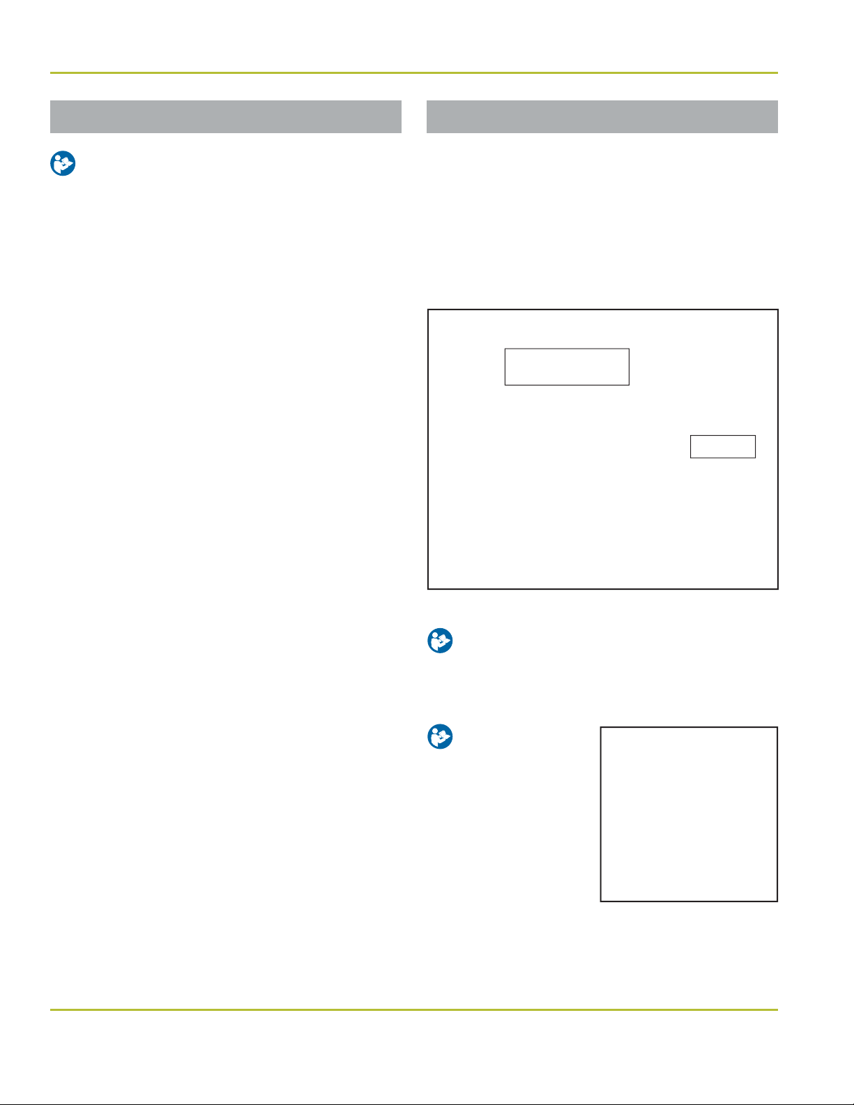
1. Disconnect the chair power.
2. Using a Phillips-head screwdriver and the
two 10-32 ×3/8 screws supplied in the kit,
attach the bracket to the lower lift arm casting
located in the base (Figure 8).
3. Route the foot control cable through the
bracket.
4. Install the wire strain relief into the bracket.
5. Plug the foot control cable into either the 6, 7,
or 13 J connection on the control board.
6. Reconnect the power to the chair and test for
proper function of the foot control.
Section III Installation
Wired Foot Control Wireless Controls
If wireless foot control and/or wireless touchpad
control options were ordered, they must be paired
with the NuSimplicity Chair.
Tools Required
• Phillips-head Screwdriver
Pair Wireless Devices to Chair
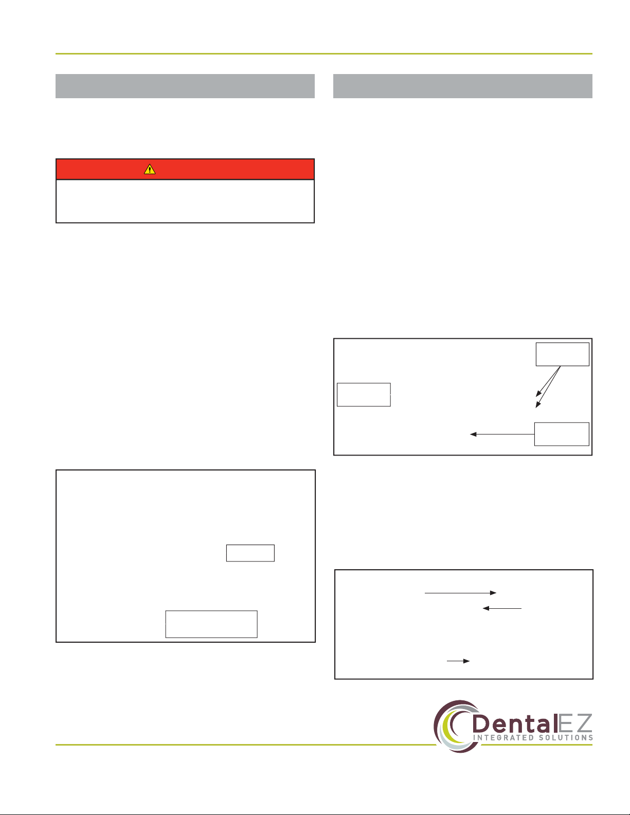
1. Raise chair base up its full UP position.
2. Remove two (2) Phillips-head screws from
front of base (pump) cover and loosen two (2)
screws in back of cover, then slide ocover
(Figure 9).
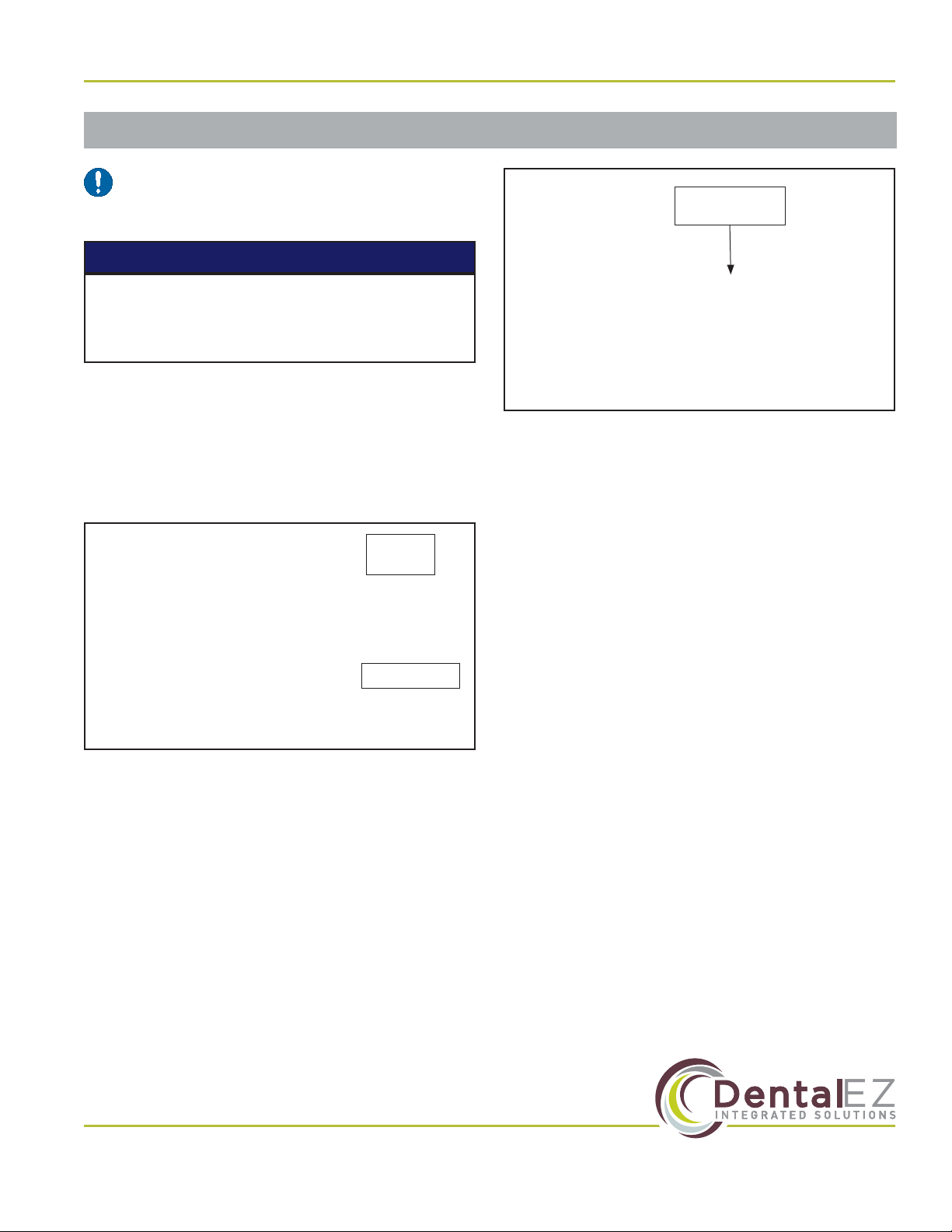
3. Make sure wireless device (foot control and/
or touchpad) has two (2) fresh AAA batteries
installed.
4. Turn wireless device to ON (Figure 10 and
Figure 11).
To prevent any chance of electrical shock,
always disconnect power when indicated.
WARNING
J Connections
Use 6, 7 or 13
Bracket
Figure 8. Control board
Remove
Screws (2)
Loosen
Screws (2)
Base Pump
Cover
Figure 9. Remove base pump cover
Battery
Compartment
ON/OFF Switch
(Shown in OFF Position)
Figure 10. ON/OFF switch for wireless foot control
Pairing
Switch

www.DentalEZ.com 866-DTE-INFO
14
NuSimplicityTM Chair
PN: 2717-256E
Section III Installation
Wireless Controls (Continued)
5. Hold down remote switch S3 on main chair
power control board for a minimum of four
(4) seconds (Figure 12). LED display on chair
cantilever cover will change to “IP” and chair
will start beeping (Figure 13).
6. Press pairing switch on bottom of device until
chair stops beeping (Figure 10 and 11).
7. Chair can have up to four (4) wireless
connections. Using chair back touchpad
control, press and hold 1, 2, 3or Abutton
until chair double beeps to store appropriate
memory location (Figure 14).
8. Check to verify that all device buttons are
working correctly.
9. Replace base (pump) cover.
Unpair Wireless Devices from Chair
1. Raise chair base up its full UP position.
2. Hold the remote switch S3 on main chair
power control board for 30 seconds. Chair will
stop beeping and wireless connections will be
cleared.
3. Re-pair other devices as needed.
Wireless Control Operation
After wireless control has been idle for an extended
period of time, foot control will go into a “sleep”
mode. Turn power switch OFF and back ON to
return the control to an active mode. If control
does not function after cycling OFF and ON, check
batteries and replace as needed.
Figure 12. ON/OFF switch for wireless touchpad control
S3 Switch
Figure 13. LED display light on cantilever cover
Figure 14. Chair back touchpad control
Figure 11. ON/OFF switch for wireless touchpad control
Pairing Switch Battery Compartment
ON/OFF Switch
ON
15
www.DentalEZ.com 866-DTE-INFO
15
DentalEZ®Equipment
PN: 2717-256E
Section III Installation
Air Glide (Optional)
NOTE: If the air glide option was ordered,
the air regulator was attached to the base
chassis prior to shipment of the chair.
1. Place the NuSimplicity Chair on a smooth, hard
and level (vinyl, tile or terrazzo type) oor.
2. Connect the air glide tubing to a regulated air
supply source (usually 552 kPa [80 PSI] on
most dental units) (Figure 15).
3. The air glide is pre-set at the factory to
138 kPa (20 PSI). Because of additional
optional equipment, it may be necessary to
increase the pressure. Slowly increase the
air pressure by adjusting the air regulator
on the base chassis until the chair begins to
“bounce”. This is an indication that the air
pillow is over-pressurized and can not seal to
the oor. Slowly decrease the pressure until
the chair stops bouncing.
4. Actuate the air regulator toggle switch
(Figure 16) at the rear of the chair on the base
cantilever section cover.
Air Regulator
Air Glide
Tubing
Figure 15. Air glide tubing connected to air regulator
5. Check for proper air glide operation.
6. Make sure the doctor and stareceive proper
air glide feature operation instructions (see Air
Glide in Section IV Operation of this manual).
Air Regulator
Toggle Switch
Figure 16. Air regulator toggle switch
For proper air glide operation, the oor MUST
BE LEVEL and have a smooth, hard and non-
obstructive surface.
NOTICE

www.DentalEZ.com 866-DTE-INFO
16
NuSimplicityTM Chair
PN: 2717-256E
Section III Installation
Upholstery
Seat
1. Obtain the 1/4-20 thumb screw provided in the
hardware package.
2. Install the upholstered seat by placing the seat
over the slide bosses in the back of the seat area
(Figure 17).
3. Once the substrate is over the bosses, pull the
seat toward the toe of the chair.
4. Align the seat frame tube to the substrate in
the toe of the chair (Figure 18) and install the
1/4-20 thumb screw.
Slide Bosses
Figure 17. Slide bosses
Substrate
1/4-20 Thumb Screw
Figure 18. Seat frame tube aligned to substrate
Back (Factory Installed)
NOTE: Make sure the blind grip fasteners are
rmly secured to the back of the upholstered
chair back.
1. Align the two upper and two lower blind grip
fasteners on the upholstered chair back to the
studs on the chair back casting (Figure 19).
2. Firmly press each blind grip fastener onto its
corresponding stud.
3. Tug on each stud location to ensure the
upholstered chair back is secure.
Blind Grip
Fasteners
Studs
Figure 19. Binder grip fasteners and studs

17
www.DentalEZ.com 866-DTE-INFO
17
DentalEZ®Equipment
PN: 2717-256E
Section III Installation
Upholstery (Continued)
Headrest
1. Slide the blade of the standard xed headrest
(Figure 20) or the optional double articulating
headrest (Figure 21) into the opening of the
back casting, making sure the blade aligns
with the nylon guides inside the chair back.
Standard
Fixed
Headrest
Blade
Figure 20. Standard xed headrest
Blade
Double
Articulating
Headrest
(Optional)
Chair Back
Casting
Opening
Figure 21. Double articulating headrest (optional)
2. Place the magnetic headrest cushion on the
chair or the xed headrest of the chair.
Magnetic
Cushion
Figure 22. Headrest shown with magnetic cushion
The headrest shown (Figure 22) contains
magnets, which can interfere with the
function of some medical devices, including
pacemakers. A minimum distance of 4" is
required to reduce the magnetic eld level
below 10 gauss.
WARNING
Table of contents
Other DentalEZ Medical Equipment manuals


Popular Medical Equipment manuals by other brands


Bosch
Bosch PFP5230 operating instructions

Cantel Medical
Cantel Medical MEDIVATORS 2-8-650HAN Hookup connection guide

Dräger Medical
Dräger Medical Narkomed MRI Operator's instruction manual

Resvent
Resvent iBreeze 20C Clinical Guide

Medacta
Medacta GMK Sphere SURGICAL TECHNIQUE

Image Diagnostics
Image Diagnostics ilex32 4K Installation and operation manual