manuals.online logo
Brands
  1. Home
  2. •
  3. Brands
  4. •
  5. Biomorph
  6. •
  7. Indoor Furnishing
  8. •
  9. Biomorph Pro SuperPlus User manual

Biomorph Pro SuperPlus User manual

Pro SuperPlus
Ground Support Equipment (US) ltd., DBA Biomorph, 11 Broadway, New York, NY 10004. Tel and Fax 888 302 3375
[email protected]
www.biomorph.com
2
Hardware
Tools
“Questions? Please call 917.328.8955 for support.
IMPORTANT: Any issues at site must be reported to Biomorph immediately at 917.328.8955, by text or phone and wait on site for response. Also, photos of
completed desk(s) must be sent to 917.328.8955 or [email protected] and wait ON SITE for approval. This will avoid potential revisits. Thank you.
Components
4mm Wrench Drill Extension #1 Phillips Bit #2 Phillips Bit Hex Bit
Leg
Qty 5
Bracket
Qty 1
3 Port Control Box
Qty 1
Wire Clips
Qty ?
Table Top
Qty 1
Cable Cab
Qty 2
45˚ Digital Readout
Switch and 45˚
Switch Bracket
Qty 2
Cable Chains
Qty 2
RH Adjustable
Crossbar Section
Qty 4
LH Adjustable
Crossbar Section
Qty 4
Adjustable
Crossbar
Qty 4
aLH Top Plate
Qty 2
bRH Top Plate
Qty 2
c
Bracket
Qty 1
e
ij k l
o
m
2 Port Control Box
Qty 1
n qp
Center Foot
Qty 1
f g h
Foot
Qty 2
d
M6 Flange Head Nut
Qty. 16
16mm PH Wd Screw
Qty. 24
M6 x 12 Screw
Qty. 72
45mm PH Wd Screw
Qty. 4
D - Glider
Qty. 6
5 x 25mm Wd Screw
Qty. 62
3
Assembly Overview
Leg Assembly
Assembly Overview
IMPORTANT:
DO NOT BUILD
THIS TABLE
UPSIDE DOWN. FRAME
MUST BE BUILT RIGHT SIDE
UP, IN PLACE, ANDTOPS
THEN ATTACHED. If this
procedure is not followed
then tops will not line up
with frame. DO NOT
REMOVE PROTECTIVE
MATERIAL FROM TOPS
UNTIL FINAL ASSEMBLY.
IMPORTANT:
When moving
this desk, do not
drag frame as it can cause
leg actuators to bind and
fail. Always lift o floor using
frame, not tops.
e
i
i
i
j
f
h
h
h
h
g
g
g
g
d
d
aa
a
b
b
c
c
M6 x 12 Screw
Qty. 16
a
a
a
a
b
b
c
c
bc
a
1
Align CPU Holder with Shroud
and secure using four (4) M6 x
8 Screws.
Slide CPU Support upward. Tighten screws using Allen
Wrench.
Note: These screws may be
loosened to re-adjust CPU
Support to accomodate
CPU.
Place Leg (A) being installed in
Step 3 into Shroud (e). Proceed
to Step 4.
Installing Leg-Mounted CPU Holder (optional)
e
f
a
M6 Flange
Head Nut
Qty. 4
M6 x 8 Screw
Qty. 4
4
Leg Assembly (continued)
a
e
4a
4b
4c
a
a
a
f
f
f
Glide
Qty. 4
M6 x 12 Screw
Qty. 8
Note: Longer end of
Foot must face toward
front (user) side.
a
a
a
a
d
d
ad
d
a
2
3
Glide
Qty. 4
M6 x 12 Screw
Qty. 16
5
Crossbar Assembly
LH Side RH Side
LH Side RH Side
g
g
h
h
g
Use these holes.
h
Use these holes.
g
Use these holes.
h
Use these holes.
M6 x 12 Screw
Qty. 8
6
M6 x 12 Screw
Qty. 8
M6 Flange
Head Nut
Qty. 8
g
Use these holes. Use these holes.
i
LH Side RH Side
g
Use these holes.
i
LH Side
h
Use these holes.
iRH Side
i
i
g
g
h
h
i
i
i
h
Crossbar Assembly (continued)
7
Crossbar Assembly (continued)
M6 x 12 Screw
Qty. 8
M6 Flange
Head Nut
Qty. 8
i
i
k
k
h
h
g
g
LH Side RH Side
Use these holes.
i
h
Use these holes.
i
g
Use these holes.
i
h
Use these holes.
i
g
LH Side RH Side
8
Crossbar Assembly (continued)
8
M6 x 12 Screw
Qty. 4
h
g
j
M6 x 12 Screw
Qty. 4
j
h
g
j
h
g
9
Top Assembly
k
k
5 x 25mm
Wood Screw
Qty. 62
10
Electrical Components
10
m
n
l
l
45˚ Digital Readout
Switch and 45˚
Switch Bracket
Qty 2
16mm PH
Wood Screw
Qty. 4
l
3 Port Control Box
Qty 1
45mm PH
Wood Screw
Qty. 2
m2 Port Control Box
Qty 1
45mm PH
Wood Screw
Qty. 2
n
11
Cable Management
Cable Cab
Qty 2
p
p
p
Cable Chains
Qty 2
o
o
o
16mm PH
Wood Screw
Qty. 8
16mm PH
Wood Screw
Qty. 6
12
Cable Diagram
IMPORTANT:
All cables must be tacked up and made neat with supplied cable guides. NO cables may hang down ex-
cept those passing through cable chains. Make sure cables have enough slack between surfaces to allow
full height adjustment between surfaces.
IMPORTANT:
Extend desktops to full opposite heights to ensure that cables will travel w/o stress).
CABLE CAB
(Optional) Place door towards user.
CABLE CHAIN
Use to run cables from front surface
to rear surface. Push in from inside.
SHORT CABLES
Use SHORT cables to connect 3 rear legs
to ports #1, #2 & #3 in controller box.
LONG CABLES
Use LONG cables to connect both front
legs to ports #1 & #2 in controller box.
GROMMET HOLE
Place grommet into
grommet hole. Route
cable accordingly.
CABLE TRACKS
Red FRONT surface
Blue REAR surface
2 PORT CONTROLLER
box for FRONT surface
SWITCH
for REAR surface use long 45˚ angle bracket.
Control switches connect to port A1.
SWITCH
for FRONT surface use long 45˚ angle bracket.
Control switches connect to port A1.
WIRE CLIP
A wire clip MUST be placed directly
behind switch to prevent cable droop
POWER CABLE
Connect power cables to power
strips inside cable cabs.
q
SWITCH
POWER CABLE
LONG CABLE/
FRONT LEG
LONG CABLE/
FRONT LEG
2 DC AC
3 4 1 A2 A1
3 PORT CONTROLLER
box for REAR surface
SHORT CABLE/REAR LEG
LONG CABLE/FRONT LEG
SWITCH
SHORT CABLE/REAR LEG
POWER CABLE
LONG CABLE/
FRONT LEG
2 DC AC
3 4 1 A2 A1
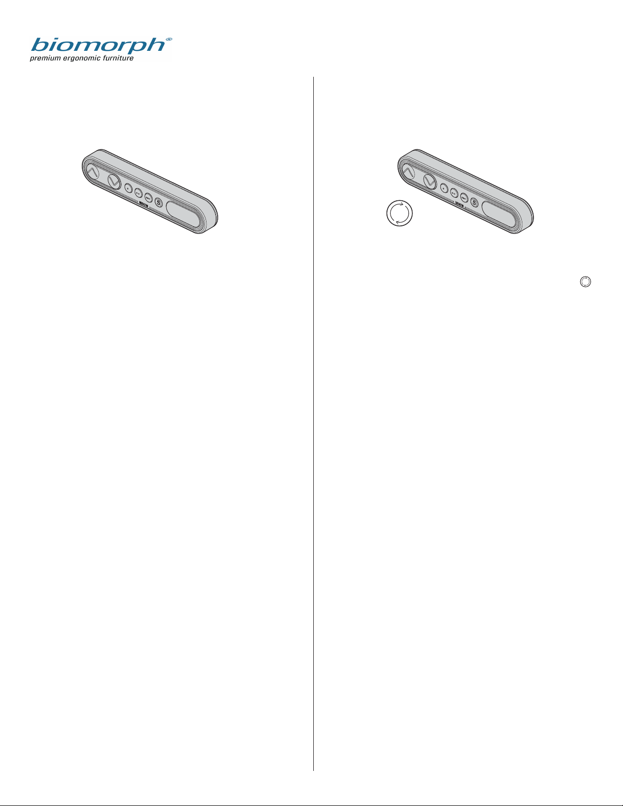
DPF4T control switch for Plus Series Dual Drive Desks
Operating your Biomorph Desk
DPF1C control switch for Level2Plus, Maxo Series, and Flexo
Series desks.
Setting Initial Height.
It may be necessary to adjust the displayed height due to dierent
thicknesses of desktops, or addition of casters, etc. The DPF1C will as
standard either show 68 cm or 24.5 inch as the default desk height.
Procedure:
Press /\ and \/ keys at the same time and keep them pressed for 5
seconds. This allows the initial height to be adjusted. Until the
initial height can be adjusted, the display will show three minuses
(---) hereafter the display will revert to showing the height. The
height can then be adjusted by either /\ or \/ until desired height
has been reached. The system will return to normal operation (and
give a short blink) after 5 seconds of inactivity on the keys.
To Adjust Height in Regular Use:
/\ = Up
V = Down
S = Store memory
• = Memory 1
•• = Memory 2
••• = Memory 3
Just push either the up or down button to adjust height and the
system will move until the button is released again or the system
reaches end position.
To Set Memory:
The four small round buttons are used for memory drive/storing
memory. To store memory
• Press S – button, the display will flash for 2 seconds
• Within these two seconds press one of the small buttons
with dots and the position will be stored at this button.
• The panel will acknowledge by showing “1”, “2” or “3” in
the display depending on chosen position (if panel is
included)
Memory drive (small round buttons with dots)
Press one of the memory buttons and the system will start driving
to the pre-programmed memory position. Keep the button pressed
until the position is reached. Release button and press again to go
past that position.
Display function (only included on dual or multiple drive tables)
shows the actual height in either cm or inch.
Dual Surface Adjustment
The DPF4T switch can operate both surfaces independently.
The default setting shows the number 1 in the digital display
which refers to the near surface. By pushing the toggle button
the display will show number 2 which will then operate the rear
surface. Press toggle again to return to number 1.
Setting Initial Height.
It may be necessary to adjust the displayed height due to dierent
thicknesses of desktops, or addition of casters, etc. The DPF4T will as
standard either show 68 cm or 24.5 inch as the default desk height.
Procedure:
Press /\ and \/ keys at the same time and keep them pressed for 5
seconds. This allows the initial height to be adjusted. Until the
initial height can be adjusted, the display will show three minuses
(---) hereafter the display will revert to showing the height. The
height can then be adjusted by either /\ or \/ until desired height
has been reached. The system will return to normal operation (and
give a short blink) after 5 seconds of inactivity on the keys. Repeat
for each surface.
To Adjust Height in Regular Use:
Choose near or rear surface using toggle button.
/\ = Up
V = Down
S = Store memory
• = Memory 1
•• = Memory 2
••• = Memory 3
Just push either the up or down button to adjust height and the
system will move until the button is released again or the system
reaches end position.
To Set Memory:
The four small round buttons are used for memory drive/storing
memory. To store memory
• Press S – button, the display will flash for 2 seconds
• Within these two seconds press one of the small buttons with
dots and the position will be stored at this button.
• The panel will acknowledge by showing “1” or “2” in the
display depend-ing on chosen position.
Memory drive (small round buttons with dots)
Press one of the memory buttons and the system will start driving
to the pre-programmed memory position for BOTH of the surfaces.
Keep the button pressed until the both positions are reached.
Release button and press again to go past that position.
Display function shows the actual height in either cm or inch.
DPF1C
May or may not have
digital display
DPF4T
Toggle between
surfaces
Questions? Call 888 302 3375
1. Check for obstructions above, below and around the
desk that may impede movement through the desk’s full
adjustment range of 22”- 48.5”. If there is anything more
than 18” high under either surface then it will cause an
obstruction and error E29 when the surface is lowered to
the lowest position to reset the system, and cause the
system to freeze.
3. Hold the DOWN button to cycle the table to its lowest
position. If the table does not move at first take your finger
o the down button, then press and release the down
button, and then immediately press and hold the down
button until the desktop is at the lowest position, aprx. 22”
o the floor.
2. Re-check the power outlet with another electrical
device to ensure that you have power to the desk.
Check power cord connection to controller box, and check
all other connections from the legs and switch(es) to the
controller box.
5. With the desk lowered in the lowest position press and
hold the down button for 5-10 seconds. The table will adjust
up and down a fraction of an inch, and may show E codes if
the switch has a display, which is normal, then show the
height. This is the sign that the table has fully reset.
4. Once the desk has lowered to its lowest point allow the
table to come to a complete stop and then take you finger
o of the down button.
Troubleshooting Guide
For Biomorph Maxo, Flexo, Level, and Plus Series Desks
Check for obstructions above, below and around the desk
that may impede movement through the desk’s full adjust-
ment range of 22”- 48.5”. If there is anything more than 18”
high under either surface then it will cause an obstruction
and error E29 when the surface is lowered to the lowest
position to reset the system, and cause the system to
freeze.
7. If the above does not work initially then unplug all
electrical connections and re-plug all connections back in to
ensure good connections with all electrical parts, and repeat
the above process. At this point the table should adjust up
and down freely. If you have a dual surface desk then this
procedure must be done with both surfaces using the
toggle button.
If the surface(es) will not move at all after the above proce-
dure note the E Code (if any) and call us at 888 302 3375 for
fur-ther troubleshooting support.
6. If the desk does not level o after pressing and holding
the down button, then press the down button again for 5-10
sec-onds until the desk adjusts up the fraction of an inch
and shows the height. This may need to be attempted up to
three times in suc-cession before movement is seen
depending on the reason why the table needs to be reset.
The digital readout may cycle through several E codes- this
is normal.

Other manuals for Pro SuperPlus

1

Other Biomorph Indoor Furnishing manuals

Biomorph Pro Plus Desk User manual

Biomorph

Biomorph Pro Plus Desk User manual

Biomorph Pro Plus User manual

Biomorph

Biomorph Pro Plus User manual

Biomorph Level 2Plus User manual

Biomorph

Biomorph Level 2Plus User manual

Biomorph Level 3Plus-95 User manual

Biomorph

Biomorph Level 3Plus-95 User manual

Biomorph XO2EL Manual

Biomorph

Biomorph XO2EL Manual

Biomorph ProPlus electric bi-level desk User manual

Biomorph

Biomorph ProPlus electric bi-level desk User manual

Biomorph Flexo Corner User manual

Biomorph

Biomorph Flexo Corner User manual

Biomorph Level 3Plus User manual

Biomorph

Biomorph Level 3Plus User manual

Biomorph Pro SuperPlus User manual

Biomorph

Biomorph Pro SuperPlus User manual

Popular Indoor Furnishing manuals by other brands

Knoll SL-Base Assembly

Knoll

Knoll SL-Base Assembly

IVY DESIGN Premium manual

IVY DESIGN

IVY DESIGN Premium manual

Walker Edison W60MAR2D Assembly instructions

Walker Edison

Walker Edison W60MAR2D Assembly instructions

Reflexion Boost 2.0 owner's manual

Reflexion

Reflexion Boost 2.0 owner's manual

Spectrum Industries Aspire 37430 Assembly instructions

Spectrum Industries

Spectrum Industries Aspire 37430 Assembly instructions

Coaster 223423 Assembly instructions

Coaster

Coaster 223423 Assembly instructions

KidKraft 65947 manual

KidKraft

KidKraft 65947 manual

Costway JV11456 manual

Costway

Costway JV11456 manual

Drive 13085L quick start guide

Drive

Drive 13085L quick start guide

Birlea URBB4RUS Assembly instructions

Birlea

Birlea URBB4RUS Assembly instructions

Otto Esstisch 0707 190-240 Assembly instructions

Otto

Otto Esstisch 0707 190-240 Assembly instructions

Neo Chair BLC Assembly instruction

Neo Chair

Neo Chair BLC Assembly instruction

Mocka Kids Rocking Horse Assembly instructions

Mocka

Mocka Kids Rocking Horse Assembly instructions

Beautify 4000050 quick start guide

Beautify

Beautify 4000050 quick start guide

INTER LINK SAS PRITTY Assembling Instruction

INTER LINK SAS

INTER LINK SAS PRITTY Assembling Instruction

Safco Plan Master Assembly instructions

Safco

Safco Plan Master Assembly instructions

Ameriwood HOME 1816296COM Instruction booklet

Ameriwood HOME

Ameriwood HOME 1816296COM Instruction booklet

Forte MADRANO MEGV711L Assembling Instruction

Forte

Forte MADRANO MEGV711L Assembling Instruction

manuals.online logo
manuals.online logoBrands
  • About & Mission
  • Contact us
  • Privacy Policy
  • Terms and Conditions

Copyright 2025 Manuals.Online. All Rights Reserved.