manuals.online logo
Brands
  1. Home
  2. •
  3. Brands
  4. •
  5. Biomorph
  6. •
  7. Indoor Furnishing
  8. •
  9. Biomorph Pro SuperPlus User manual

Biomorph Pro SuperPlus User manual

Pro SuperPlus
Ground Support Equipment (US) ltd., DBA Biomorph, 11 Broadway, New York, NY 10004. Tel and Fax 888 302 3375
[email protected]
www.biomorph.com
SXV5MAAAAFF-C-B-DSDS
SXV5MAAAAFF-C-S-DSDS
2
Hardware
Tools
“Questions? Please call 917.328.8955 for support.
IMPORTANT: Any issues at site must be reported to Biomorph immediately at 917.328.8955, by text or phone and wait on site for response. Also, photos of
completed desk(s) must be sent to 917.328.8955 or [email protected] and wait ON SITE for approval. This will avoid potential revisits. Thank you.
Components
4mm Wrench Drill Extension #1 Phillips Bit #2 Phillips Bit Hex Bit
Leg
Qty 5
Bracket
Qty 1
3 Port Control Box
Qty 1
Table Top
Qty 1
Cable Cab
Qty 2
45˚ Digital Readout
Switch and 45˚
Switch Bracket
Qty 2
Cable Chains
Qty 2
RH Adjustable
Crossbar Section
Qty 4
LH Adjustable
Crossbar Section
Qty 4
Adjustable
Crossbar
Qty 4
aLH Top Plate
Qty 2
bRH Top Plate
Qty 2
c
Bracket
Qty 1
e
ij k l
o
m
2 Port Control Box
Qty 1
n qp
Center Foot
Qty 1
f g h
Foot
Qty 2
d
M6 Flange Head Nut
Qty. 16
16mm PH Wd Screw
Qty. 24
M6 x 12 Screw
Qty. 72
45mm PH Wd Screw
Qty. 4
D - Glider
Qty. 6
5 x 25mm Wd Screw
Qty. 62
Wire Clips
Qty 26
3
Assembly Overview
Leg Assembly
Assembly Overview
IMPORTANT:
DO NOT BUILD
THIS TABLE
UPSIDE DOWN. FRAME
MUST BE BUILT RIGHT SIDE
UP, IN PLACE, AND TOPS
THEN ATTACHED. If this
procedure is not followed
then tops will not line up
with frame. DO NOT
REMOVE PROTECTIVE
MATERIAL FROM TOPS
UNTIL FINAL ASSEMBLY.
IMPORTANT:
When moving
this desk, do not
drag frame as it can cause
leg actuators to bind and
fail. Always lift o floor using
frame, not tops.
e
i
i
i
j
f
h
h
h
h
g
g
g
g
d
d
aa
a
b
b
c
c
M6 x 12 Screw
Qty. 16
a
a
a
a
b
b
c
c
bc
a
1
Align CPU Holder with Shroud
and secure using four (4) M6 x
8 Screws.
Slide CPU Support upward. Tighten screws using Allen
Wrench.
Note: These screws may be
loosened to re-adjust CPU
Support to accomodate
CPU.
Place Leg (A) being installed in
Step 3 into Shroud (e). Proceed
to Step 4.
Installing Leg-Mounted CPU Holder (optional)
e
f
a
M6 Flange
Head Nut
Qty. 4
M6 x 8 Screw
Qty. 4
4
Leg Assembly (continued)
a
e
4a
4b
4c
a
a
a
f
f
f
Glide
Qty. 4
M6 x 12 Screw
Qty. 8
Note: Longer end of
Foot must face toward
front (user) side.
a
a
a
a
d
d
ad
d
a
2
3
Glide
Qty. 4
M6 x 12 Screw
Qty. 16
5
Crossbar Assembly
LH Side RH Side
LH Side RH Side
g
g
h
h
g
Use these holes.
h
Use these holes.
g
Use these holes.
h
Use these holes.
M6 x 12 Screw
Qty. 8
6
M6 x 12 Screw
Qty. 8
M6 Flange
Head Nut
Qty. 8
g
Use these holes. Use these holes.
i
LH Side RH Side
g
Use these holes.
i
LH Side
h
Use these holes.
iRH Side
i
i
g
g
h
h
i
i
i
h
Crossbar Assembly (continued)
7
Crossbar Assembly (continued)
M6 x 12 Screw
Qty. 8
M6 Flange
Head Nut
Qty. 8
i
i
k
k
h
h
g
g
LH Side RH Side
Use these holes.
i
h
Use these holes.
i
g
Use these holes.
i
h
Use these holes.
i
g
LH Side RH Side
8
Crossbar Assembly (continued)
8
M6 x 12 Screw
Qty. 4
h
g
j
M6 x 12 Screw
Qty. 4
j
h
g
j
h
g
9
Top Assembly
k
k
5 x 25mm
Wood Screw
Qty. 62
10
Electrical Components
10
m
n
l
l
45˚ Digital Readout
Switch and 45˚
Switch Bracket
Qty 2
16mm PH
Wood Screw
Qty. 4
l
3 Port Control Box
Qty 1
45mm PH
Wood Screw
Qty. 2
m2 Port Control Box
Qty 1
45mm PH
Wood Screw
Qty. 2
n
11
Cable Management
Cable Cab
Qty 2
p
p
p
Cable Chains
Qty 2
o
o
o
16mm PH
Wood Screw
Qty. 8
16mm PH
Wood Screw
Qty. 6
12
Cable Diagram
IMPORTANT:
All cables must be tacked up and made neat with supplied cable guides. NO cables may hang down ex-
cept those passing through cable chains. Make sure cables have enough slack between surfaces to allow
full height adjustment between surfaces.
IMPORTANT:
Extend desktops to full opposite heights to ensure that cables will travel w/o stress).
CABLE CAB
(Optional) Place door towards user.
CABLE CHAIN
Use to run cables from front surface
to rear surface. Push in from inside.
SHORT CABLES
Use SHORT cables to connect 3 rear legs
to ports #1, #2 & #3 in controller box.
LONG CABLES
Use LONG cables to connect both front
legs to ports #1 & #2 in controller box.
GROMMET HOLE
Place grommet into
grommet hole. Route
cable accordingly.
CABLE TRACKS
2 PORT CONTROLLER
box for FRONT surface
SWITCH
for REAR surface use long 45˚ angle bracket.
Control switches connect to port A1.
SWITCH
for FRONT surface use long 45˚ angle bracket.
Control switches connect to port A1.
WIRE CLIP
A wire clip MUST be placed directly
behind switch to prevent cable droop
POWER CABLE
Connect power cables to power
strips inside cable cabs.
q
SWITCH
POWER CABLE
LONG CABLE/
FRONT LEG
LONG CABLE/
FRONT LEG
2 DC AC
3 4 1 A2 A1
3 PORT CONTROLLER
box for REAR surface
SHORT CABLE/REAR LEG
LONG CABLE/FRONT LEG
SWITCH
SHORT CABLE/REAR LEG
POWER CABLE
LONG CABLE/
FRONT LEG
2 DC AC
3 4 1 A2 A1
Questions? Call 888 302 3375
DPF1C control switch for Level Series, Flexo Series, and Pro SuperPlus and Level 3Plus-95 desks with 5 legs.
NOTE: DPF1C may or may not have digital display
Operating your Biomorph Desk
Setting Initial Height.
It may be necessary to adjust the displayed height due to dierent
thicknesses of desktops, or addition of casters, etc. The DPF1C will as
standard either show 68 cm or 24.5 inch as the default desk height.
Procedure
Press and keys at the same time and keep them pressed
for 5 seconds. This allows the initial height to be adjusted.
UP DOWN
MEMORY 1
MEMORY 2
MEMORY 3
STORE MEMORY
DIGITAL DISPLAY
5 sec.
1
Until the initial height can be adjusted, the display will show three
minuses . Hereafter the display will revert to showing the
height. The height can then be adjusted by either or until
desired height has been reached. The system will return to
normal operation (and give a short blink) after 5 seconds of
inactivity on the keys.
2
Keep the button pressed until the position is reached. Release
button and press again to go past that position.
Press one of these memory buttons and the
system will start driving to the pre-programmed memory position.
1
2
Display function (only included on dual or multiple drive tables)
shows the actual height in either cm or inch.
3
To Set Memory.
These buttons are used for memory drive/storing
memory. To store memory:
Press . The display will flash for 2 seconds. Within these two
seconds press one of these buttons and the position
will be stored at this button.
1
The panel will acknowledge by showing , or in the display
depending on chosen position (if panel is included).
2
Memory Drive.
To Raise or Lower Height in Regular Use.
Push the button to raise
the height or the button
to lower the height. The
system will move until the
button is released again or
the system reaches end
position.
48.6”
22.1”
Side View
©2021 GSE (US) LTD.
Questions? Call 888 302 3375
DPF1C control switch for Biomorph Level, Flexo, and DPF4T control switch for Plus Series Desks .
Troubleshooting Guide
Hold the button to cycle the table to its lowest position. If
the table does not move at first take your finger o the
button, and then immediately press and hold the button until
the desktop is at the lowest position, aprx. 22”
3
Once the desk has lowered to its lowest point allow the table to
come to a complete stop and then take you finger o the
button.
4
For dual surface Plus Series desks, you must reset both
front and rear surfaces, by starting with the front then using
the button to operate the rear surface and repeating the
procedure.
If the desk does not level o after pressing and holding the
button, then press the button again for 5-10 seconds until the
desk adjusts up the fraction of an inch and shows the height. This
may need to be attempted up to three times in succession before
movement is seen depending on the reason why the table needs
to be reset. The digital readout may cycle through several E codes
- this is normal.
6
If the above does not work initially then unplug all electrical
connections and check all female connections to ensure all pins
are sticking out straight and not bent over or pushed in. Hit the
down button 10 times to remove all voltage from the system.
Wait 30 seconds and re-plug all connections back in to ensure
good connections with all electrical parts, and repeat the above
process.
At this point the table should adjust up and down freely.
If you have a dual surface desk then this procedure must be done
with both surfaces using the button.
If the surface(s) will not move at all after the above procedure
note the E Code (if any) and call us at 888.302.3375 for further
troubleshooting support.
7
Re-check the power outlet with another electrical device to
ensure that you have power to the desk. Check power cord
connection to controller box, and check all other connections
from the legs and switch(es) to the controller box.
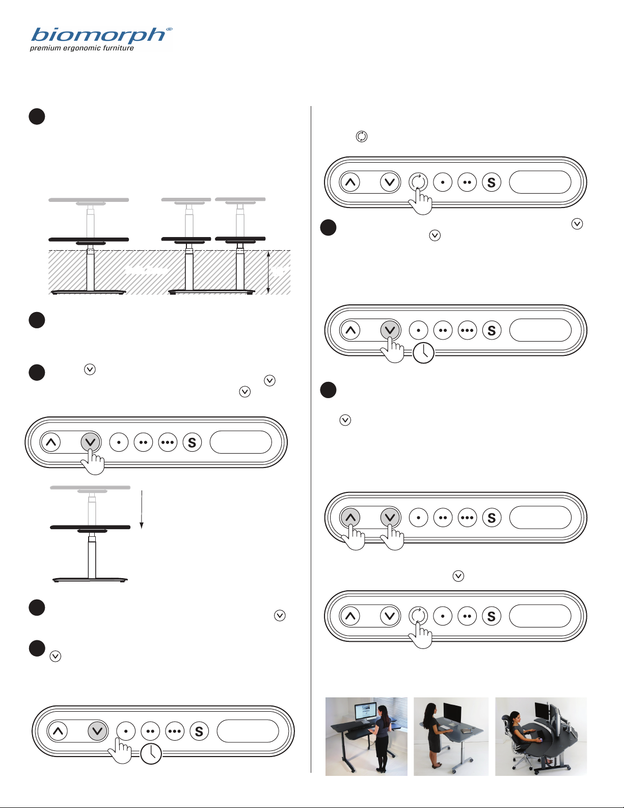
2
Check for obstructions above, below and around the desk that
may impede movement through the desk’s full adjustment
range of 22” - 48.5”. If there is anything more than 18” high
under either surface (or outside the “safe zone”) then it will
cause an obstruction and error E29 when the surface is lowered
to the lowest position to reset the system, and cause the
system to freeze.
1
22”
Side View
5-10 sec.
With the desk lowered in the lowest position press and hold the
button for 5-10 seconds. The table will adjust down and then
up a fraction of an inch, and may show E codes if the switch has
a display, which is normal, then show the height. This is the sign
that the table has fully reset.
5
5-10 sec.
Side View Side View
18”18”
Safe ZoneSafe Zone
Flexo Series Level Series Plus Series

Other manuals for Pro SuperPlus

1

This manual suits for next models

2

Other Biomorph Indoor Furnishing manuals

Biomorph ProPlus electric bi-level desk User manual

Biomorph

Biomorph ProPlus electric bi-level desk User manual

Biomorph Pro Plus Desk User manual

Biomorph

Biomorph Pro Plus Desk User manual

Biomorph Pro Plus User manual

Biomorph

Biomorph Pro Plus User manual

Biomorph Level 2Plus User manual

Biomorph

Biomorph Level 2Plus User manual

Biomorph Level 3Plus-95 User manual

Biomorph

Biomorph Level 3Plus-95 User manual

Biomorph Flexo Corner User manual

Biomorph

Biomorph Flexo Corner User manual

Biomorph Pro SuperPlus User manual

Biomorph

Biomorph Pro SuperPlus User manual

Biomorph Level 3Plus User manual

Biomorph

Biomorph Level 3Plus User manual

Biomorph XO2EL Manual

Biomorph

Biomorph XO2EL Manual

Popular Indoor Furnishing manuals by other brands

Hillsdale Furniture URBAN QUARTERS YOUTH JR 101818-104788 manual

Hillsdale Furniture

Hillsdale Furniture URBAN QUARTERS YOUTH JR 101818-104788 manual

Gunnebo GlasStile GSR Installation, operation and maintenance manual

Gunnebo

Gunnebo GlasStile GSR Installation, operation and maintenance manual

Germania 1366 Assembly instruction

Germania

Germania 1366 Assembly instruction

Desalto Ellis Assembly instruction

Desalto

Desalto Ellis Assembly instruction

avaks REA AMY 29/90 Assembly instructions

avaks

avaks REA AMY 29/90 Assembly instructions

Next 697901 Assembly instructions

Next

Next 697901 Assembly instructions

Kinder Valley Chester Rocking Stand Assembly instructions

Kinder Valley

Kinder Valley Chester Rocking Stand Assembly instructions

BELLATERRA HOME 804338 Assembly/installation instructions

BELLATERRA HOME

BELLATERRA HOME 804338 Assembly/installation instructions

BluDot Hall Pass Wall Shelf With Hooks Assembly notes

BluDot

BluDot Hall Pass Wall Shelf With Hooks Assembly notes

VENETA 37103-64500-B How to install

VENETA

VENETA 37103-64500-B How to install

S-Thetique S-tool Plus 50165 manual

S-Thetique

S-Thetique S-tool Plus 50165 manual

Skutchi SAPslim Cubicle System installation guide

Skutchi

Skutchi SAPslim Cubicle System installation guide

NTense 8141013COM Instruction booklet

NTense

NTense 8141013COM Instruction booklet

StyleWell BS80792 Use and care guide

StyleWell

StyleWell BS80792 Use and care guide

Synergy 303 instructions

Synergy

Synergy 303 instructions

Sauder 412740 Assembly instructions

Sauder

Sauder 412740 Assembly instructions

Alera ALE-VA72QR3030 instructions

Alera

Alera ALE-VA72QR3030 instructions

Balkene Home Vashon Aluminum Patio Bistro Set 63290 Assembly instructions

Balkene Home

Balkene Home Vashon Aluminum Patio Bistro Set 63290 Assembly instructions

manuals.online logo
manuals.online logoBrands
  • About & Mission
  • Contact us
  • Privacy Policy
  • Terms and Conditions

Copyright 2025 Manuals.Online. All Rights Reserved.