Bionics TX-2300KFP Instruction Manual

Bionics Instrument
© 2004 Eur 20040426, all rights reserved
Guide to Installation and Operation
Gas Detector
TX-KFP


TX-KFP
Bionics Instrument
© 2004 Eur 20040426, all rights reserved
Copyright Information
Copyright © 2004 by Bionics Instrument Europe B.V. All rights reserved.
No part of the contents of this publication may be reproduced or transmitted in any form or
by any means without the explicit written permission of Bionics Instrument Europe B.V.,
Maxwellstraat 7, 1704 SG Heerhugowaard, The Netherlands.
We are of opinion that the instructions and information found in this publication are both
useful and accurate.
However, please be aware that errors may exist in this publication, and that neither the
authors nor Bionics Instrument Europe B.V. make any guarantees concerning the accuracy of
the information found here or in the use to which it may be put.
Information in this manual may be subject to change without prior notice and does not
represent a commitment on the part of the vendor.
Printed in the Netherlands2004


TX-KFP
Bionics Instrument
© 2004 Eur 20040426, all rights reserved
1: INTRODUCTION.........................................................................................................- 7 -
1.1 INSTRUMENT OVERVIEW ................................................................................................ - 7-
1.2 PARTS IDENTIFICATION TX-KFP .................................................................................... - 8-
1.3 SYSTEM OVERVIEW ........................................................................................................ - 9-
1.4 IDENTIFICATION OF BIONICS SYSTEMS AND COMPONENTS ................................................ - 9-
1.5 PRODUCT OPTIONS ....................................................................................................... - 11 -
1.6 SAFETY ........................................................................................................................ - 12 -
2. SPECIFICATIONS..................................................................................................... - 13 -
2.1 TECHNICAL SPECIFICATIONS ......................................................................................... - 13 -
2.1.1 General Specifications (gas sensor types: DP/ELP and MP) .................................- 13 -
2.1.2 General Specifications (gas sensor type: BP)........................................................- 13 -
2.2 DIMENSIONAL DRAWINGS ............................................................................................. - 14 -
3. INSTALLATION ........................................................................................................ - 15 -
3.1 MOUNTING .................................................................................................................. - 15 -
3.1.1 Gas sensor types for the TX-KFP..........................................................................- 15 -
3.1.2 Mounting of the gas sensor types BP and MP .......................................................- 16 -
3.1.3 Mounting of the gas sensor types DP and ELP......................................................- 17 -
3.2 MOUNTING THE GAS DETECTION UNIT ........................................................................... - 18 -
3.2.1 Wall- or ceiling-mounting of the gas detection unit...............................................- 19 -
3.3 DUCT MOUNTING OF THE TX-KFP IN EXHAUST SYSTEMS ............................................... - 22 -
3.4 ELECTRICAL CONNECTIONS GENERAL........................................................................... - 23 -
3.4.1 Wiring details for PC-5028 board ........................................................................- 24 -
3.4.2 Wiring details for analogue/digital local indicator................................................- 24 -
3.5 START-UP .................................................................................................................... - 25 -
4. CONFIGURATION .................................................................................................... - 26 -
4.1 CONFIGURING THE DIGITAL DISPLAY TX-KFP-D ........................................................... - 26 -
5. OPERATION .............................................................................................................. - 27 -
5.1 MAINTEN ANCE ............................................................................................................. - 27 -
5.1.1 Maintenance procedure for the GS-[…]DP type sensor.........................................- 27 -
5.2 CALIBRATION ............................................................................................................... - 32 -
5.2.1 Setting-up the calibration procedure.....................................................................- 32 -
5.2.2 Calibration procedure using a local indicator ......................................................- 33 -
5.2.3 Calibration procedure using a multi-meter ...........................................................- 33 -
5.3 SPAN RESPONSE TEST.................................................................................................... - 34 -
APPENDIX 1- PRINCIPLE OF MEMBRANE ELECTROLYSIS ............................... - 35 -
APPENDIX 2 - CALIBRATION KIT AND ACCESSORIES ....................................... - 36 -
APPENDIX 3 - TRANSPORTATION............................................................................ - 37 -
APPENDIX 4 - BIONICS INSTRUMENT OFFICES AND SERVICE CENTERS...... - 38 -


TX-KFP
Bionics Instrument
© 2004 Eur 20040426, all rights reserved
- 7 -
1: Introduction
1.1 Instrument Overview
The TX-KFP series are highly reliable stand-alone systems capable of detecting a wide variety
of toxic, corrosive and flammable gases both in low parts per million (ppm) concentrations as
well as in the higher concentrations (vol. %).
The key element of the system is an electrochemical sensor which has been designed for a
highly selective response to a specific gas or group of gases.
The gas detector models TX-KFP are diffusion type systems designed for use as
environmental gas detection system or as in-line gas detection system for exhaust systems.
The sensor is capable to operate under high humidity conditions and may be used as a stand-
alone system or linked to an optional control system.
The industry standard KF40 vacuum type flange connection allows for quick and easy
installation.
Features:
An electrochemical gas sensor, maintainable for almost all types
24 V DC operated / 4 - 20 mA output
Local display of gas concentration (analogue or digital indication)
Test and calibration with ‘live gas’ in safe concentrations
A good zero stability and high sensitivity.
Calibration both on- and off-site
Easy mounting by means of industry standard KF-connection

TX-KFP
Bionics Instrument
© 2004 Eur 20040426, all rights reserved
- 8 -
Cable by client
Fig. 1.2.1
6
4
6
5
9
3
1 2
8
7
1: Introduction
1.2 Parts Identification TX-KFP
1) For DP and ELP sensor type only!
1 – KF-40 type Body, incl. PC-1280RL &
PC-1280-KF PC-Boards
2 – Plug-in socket
3 – Silicon locking ring 1)
4 – Retaining ring
5 – Gas detection cell
(Model: DP, ELP, MP or BP)
6 – Cover plate
7 – DIN Connector, type KGV-60
(female 6-pole)
8 – Power supply/signal cable (2.5 m),
incl. DIN Connector, type SV-60
(male 6-pole)
9 – Junction box, incl. 2x PG-9 cable
grommets

TX-KFP
Bionics Instrument
© 2004 Eur 20040426, all rights reserved
- 9 -
1: Introduction
1.3 System Overview
The key element of the TX-KFP is an electrochemical gas sensor. Nearly all types operate
according to the principle of membrane electrolysis. See appendix 2 for an explanation of the
membrane electrolysis principle.
The TX-KFP operates on 24-Volt DC, usually supplied by an alarm/control unit.
The signal coming from the gas sensor is converted into a 4-20mA signal and transferred
through the 2 wire shielded cable to the alarm/control unit.
Signal transmission can take place over distances up to 1000 meters.
The industry standard KF40 vacuum type flange connection allows for quick and easy
installation.
Fig.1.3.1 gives an overview of some possible configurations.
1.4 Identification of Bionics systems and components
Bionics Instrument uses a Toxic Gas (TG) number to identify a gas or group of gases. This
number is a ‘100’ number. For example; Ammonia is TG-2400.
For a full list of the TG codes please refer to our documentation.
The Gas Sensor (GS) number has been derived from the TG number. This means the GS
number for a specific gas or group of gases will start with the same ‘100’ number. For
example; the GS-2460DP is a sensor for the detection of ammonia. The GS number is followed
by a code identifying the type of sensor.
Accordingly a TX-KFP for use with a GS-2460DP gas sensor is identified by:
TX-[2460]KFP
BP - exchangeable electrochemical sensor
DP - refillable electrochemical sensor
EP - exchangeable electrochemical sensor
ELP - exchangeable electrochemical sensor
MP - exchangeable electrochemical sensor
Other identification codes used in this manual:
PC- Printed Circuit board
RX- Alarm/Control Unit
A- Analogue Display
D- Digital Display
EL- Electrolyte
M- Membrane

TX-KFP
Bionics Instrument
© 2004 Eur 20040426, all rights reserved
- 10 -
1: Introduction
Fig. 1.3.1

TX-KFP
Bionics Instrument
© 2004 Eur 20040426, all rights reserved
- 11 -
1: Introduction
1.5 Product options
The standard supply of the TX-KFP unit includes a junction box with 2.5 meters of 2-wire
shielded cable (2x 0.75 mm2), connected at one end to the junction box and the other end
provided with a SV-60 type DIN connector (see fig. 1.2.1), a gas sensor fastening tool and an
installation and operation manual.
However, for easy installation and to suit your specific installation requirements, a number of
optional items can be ordered from Bionics Instrument.
- Wiring options:
Cable – 2 wire (2x 0.75 mm2) shielded, length= 6 m or any length up to 1000 m.
- Local Display options:
Local Analogue Indicator – scale, depending on application, in ppb, ppm or vol. %
Local Digital Indicator – scale, depending on application, in ppb, ppm or vol. %
- Mounting options:
1: “Clip-in” wall mount set SH-40 (see fig. 3.2.2)
Model no. Mounting
Style
Gas Sensor
Type Colour
SH-40 Wall All types Black
2: (KFP Wall/Ceiling mount adapter):
Holder set for wall- or ceiling- mounting provided in white or black.
The unit comes complete with either wall mount bracket or ceiling mount bracket
(see fig. 3.2.3/3.2.4/3.2.5)
Model no. Mounting
Style
Gas Sensor
Type Colour
WM-40L/B Wall All types Black
CM-40L/B Ceiling All types Black
WM-40L/W Wall All types White
CM-40L/W Ceiling All types White
- Gas sensor protection option:
A sensor protection jacket (black PVC), see fig. 2.2.3

TX-KFP
Bionics Instrument
© 2004 Eur 20040426, all rights reserved
- 12 -
1: Introduction
1.5 Product options (Cont’d)
- Duct mounting set:
To duct mount the TX-KFP the following set of materials is available (see fig. 3.3.2):
Item Description
1 KF-40 nozzle 90 mm
2 KF-40 clamp
3 Gasket (Centring ring + O-ring)
- Calibration materials:
A complete calibration kit containing all necessary calibration aids can be ordered
(see appendix – 2 for a detailed description of the calibration kit).
1.6 Safety
This gas detection system has been designed to provide long-term reliable performance.
Nevertheless, we advise you to take the following basic precautions whilst installing
operating and maintaining this device.
Read this “Guide to Installation and Operation” carefully.
Be sure to file this guide for future reference.
Installation, maintenance, calibration and testing should be carried out
by qualified personnel only.
Check if the power supply matches the specifications given in this guide and
ensure that the system has been connected properly.
If you have any doubt with regard to the power supply, please contact one of the
Bionics Instrument Offices 1).
If there are any signs of system damage or malfunctioning, please switch
the alarm/control unit to ‘Stand-by mode’ and contact one of the Bionics
Instrument Offices 1).
1) For Bionics Instrument Offices see Appendix 4

TX-KFP
Bionics Instrument
© 2004 Eur 20040426, all rights reserved
- 13 -
2. Specifications
2.1 Technical specifications
2.1.1 General Specifications (gas sensor types: DP/ELP and MP)
*) [….] = TG number e.g TX-[1550]KFP
2.1.2 General Specifications (gas sensor type: BP)
Device type TX-[….]KFP *)
Power requirements 24 V DC / 50 mA max
Operating temperature 0 – 35 OC
Indicator LED for power on
Installation method Wall-, ceiling-, or duct- mounted
Output signal 4-20 mA, 2-wire closed loop
Output drive capacity 0 – 600 Ω
Dimensions 69 Øx ~ 130 mm lg.
Weight Approx 1.5 kg
Power consumption 1.25 W
Transmitter Board 1280 KF/RL
Device type TX-[2300]KFP
Power requirements 24 V DC / 300 mA max
Operating temperature 0 – 35 OC
Indicator LED for power on
Installation method Wall-, ceiling-, or duct- mounted
Output signal 4-20 mA, 3-wire
Output drive capacity 0 – 600 Ω
Dimensions 69 Øx ~ 78 mm lg.
Weight Approx 1.5 kg
Power consumption 8 W max.
Pre-amplifier board PC-5056
Post-amplifier board PC-5057
TX-KFP
Bionics Instrument
© 2004 Eur 20040426, all rights reserved
- 14 -
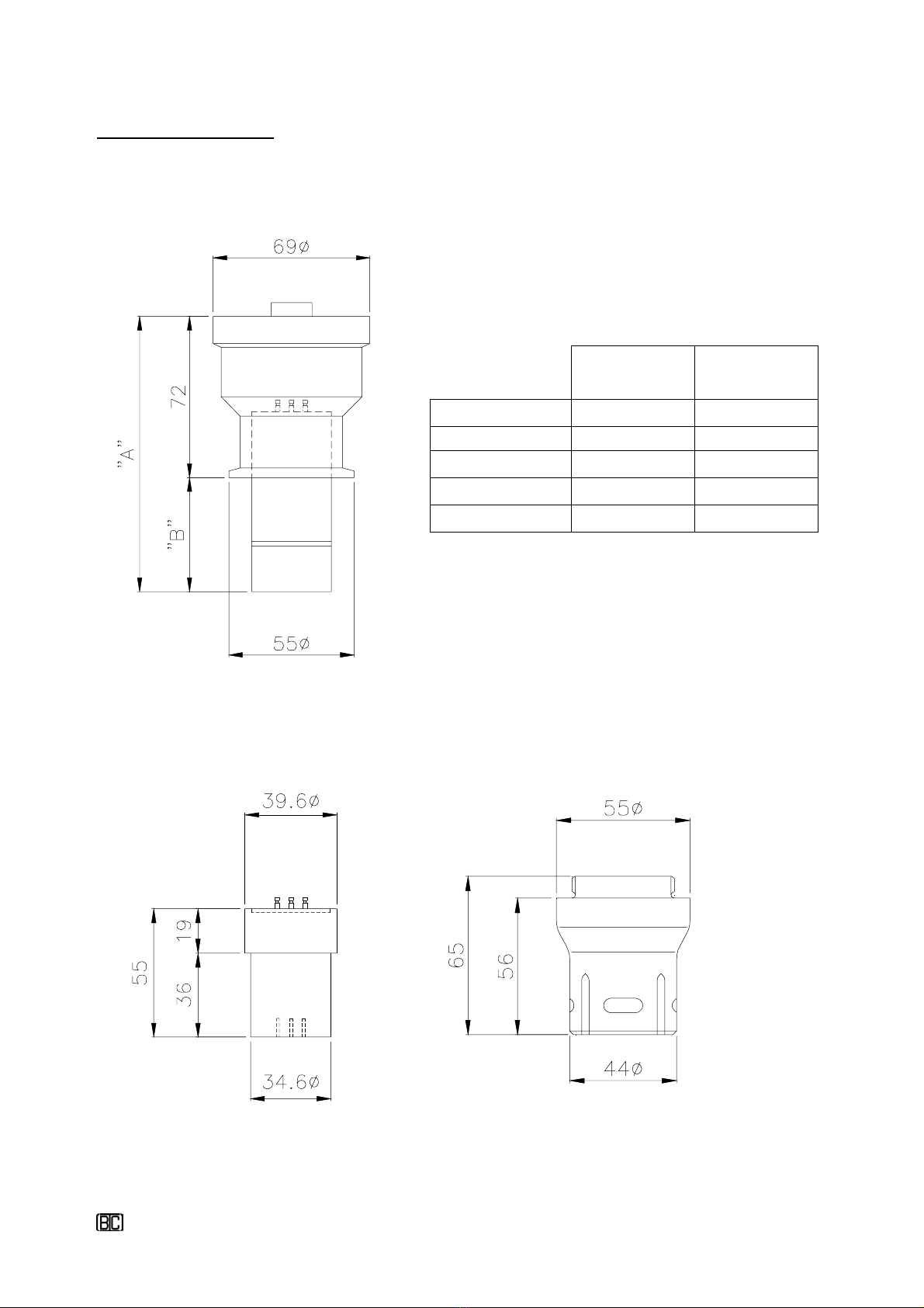
Fig. 2.2.1
Fig. 2.2.2 Fig. 2.2.3
Specifications
2.2 Dimensional drawings
Sensor
Type Fitted
Dimension
“A”
Dimension
“B”
BP sensor*) ~120 ~48
DP sensor*) ~123 ~51
ELP sensor ~125 ~53
MP sensor ~125 ~53
*) Incl. EP-adapter (Extended plug
-
in adapter)
- TX-KFP assembly
- EP adapter (Extended Plug
-
in adapter) - Sensor Protection Jacket

TX-KFP
Bionics Instrument
© 2004 Eur 20040426, all rights reserved
- 15 -
Fig. 3.1.1
3. Installation
3.1 Mounting
General mounting procedures:
Allow for sufficient space around the unit for cable connector insertion/withdrawal.
Mount the unit at such a location that the unit is easily accessible for wiring and maintenance
activities.
3.1.1 Gas sensor types for the TX-KFP
The TX-KFP can be fitted with the following plug-in type gas sensors:
- BP gas sensor, in combination with an EP-adapter *)
- DP gas sensor
- ELP gas sensor
- MP gas sensor, in combination with an EP-adapter*)
*) For EP-adapter (Extended Plug-in adapter) see section 2.2, fig. 2.2.2
- BIAS voltage control
In order to optimise the sensor stabilisation time when a new sensor is being installed, a BIAS
voltage control provision is applied.
The type of provision depends on the gas sensor’s TG no’s.
For most of the TG no’s the gas sensor working electrode “W” is
short-circuited with the gas sensor reference electrode “R” by
means of a spring, see fig. 3.1.1
Note:
Keep the spring, as it is recommended to re-fit the spring
in case the sensor needs to be transported or stored for a longer
period
The TX-KFP series is designed for indoor use only,
for outdoor use please refer to the TX-KXP series.

TX-KFP
Bionics Instrument
© 2004 Eur 20040426, all rights reserved
- 16 -
1
4
6
7
5
3
2
Fig. 3.1.3
Plug-on
Black
White
Connector
3. Installation
3.1.1 Gas sensor types for the TX-KFP (Cont’d)
3.1.2 Mounting of the gas sensor types BP and MP
The TX-KFP unit comes pre-assembled with items 1, 2 and 3.
To install the BP- or MP-type gas sensor into the TX-KFP body, proceed as follows.
For gas sensors with TG no.’s: 170/270/880/
1560 and 1750 the “BIAS voltage control” is
activated through a 1.5 Volts battery device,
see fig. 3.1.2.
Make sure that in case you have to reconnect
the device, the battery’s voltage has not
dropped under the required voltage level of
1.2 V.
- Remove the “BIAS voltage control” provision,
see section 3.1.1.
- Push the EP-adapter (5) gently upwards into the
KF body (1) through the retaining ring (4)
until it snaps into the sensor socket (2).
- Plug the BP- or MP-type sensor (6) into the EP-
adapter.
- Slide the fastening tool (7) over the sensor until
the tool projections snap into the notches of the
retaining ring (4). Turn anti-clockwise to secure
the sensor with the retaining ring.
Fig. 3.1.2

TX-KFP
Bionics Instrument
© 2004 Eur 20040426, all rights reserved
- 17 -
Fig. 3.1.4
1
4
6
7
5
3
2
3. Installation
3.1.3 Mounting of the gas sensor types DP and ELP
The TX-KFP unit comes pre-assembled with items 1, 2, 3, 4 and 5
To install the DP- or ELP-type gas sensor into the TX-KFP body follow the following steps.
- Remove the “BIAS voltage control” provision, see section
3.1.1.
- Push the DP- or ELP-type gas sensor (6) gently upwards
into the KF body (1) through the retaining ring (5) and
silicon locking ring (4) until it snaps into the sensor
socket (2).
If you feel a restraint when pushing the sensor upwards
you must loosen the retaining ring and silicon ring.
- Slide the fastening tool (7) over the sensor until the
tool projections snap into the notches of the retaining
ring (5). Turn anti-clockwise until some pressure is felt,
then apply further pressure to ensure that
the silicon locking ring grips firmly around the sensor.
Note:
To remove the gas sensor proceed in reverse order

TX-KFP
Bionics Instrument
© 2004 Eur 20040426, all rights reserved
- 18 -
If installed at an angle,
make sure that the
ʺpressure equalisingʺscrew
always faces upwards!
3. Installation
3.2 Mounting the gas detection unit
The TX-KFP unit can be installed as an environmental gas detector, whereby a choice can be
made between wall- or ceiling– mounting the unit or the gas detector may be duct-mounted
for monitoring applications in exhaust systems.
Fig. 3.2.1
The TX-KFP unit should preferably
be installed vertically.
In case the unit needs to be installed
under an angle, please make sure
that the unit is never placed under
an angle greater than 45° relative to
a vertical position (see figure 3.2.1).
This is to ensure that the main
electrode is always in contact with a
sufficient amount of electrolyte.
If the TX-KFP is placed under an
angle the ’pressure stabilization
screw ‘ should always face up
wards.

TX-KFP
Bionics Instrument
© 2004 Eur 20040426, all rights reserved
- 19 -
3. Installation
3.2.1 Wall- or ceiling-mounting of the gas detection unit
- Wall mounting:
For wall-mount installation there are two options.
Option 1: Using the “Clip-in” wall mount set (optional item)
Option 2: Using the KFP-Wall/Ceiling mount adapter (optional item)
Option 1 (“Clip-in” wall mount set SH-40):
The set consists of two parts:
1 - Mounting plate, see fig. 3.2.2b
2 - Support ring, see fig. 3.2.2a
If not fitted already, fit the support ring with M4 bolts to the mounting plate.
Drill holes at the required distances (for details see fig. 3.2.2b) and fit the mounting plate with
M6 bolts or equally sized screws to the wall. Place the unit into the support ring, see fig. 3.2.2c.
Fig. 3.2.2b
Fig. 3.2.2a
Fig. 3.2.2c

TX-KFP
Bionics Instrument
© 2004 Eur 20040426, all rights reserved
- 20 -
Fig. 3.2.3
Fig. 3.2.4
3. Installation
3.2.1 Wall- or ceiling-mounting of the gas detection unit (Cont’d)
Option 2 (KFP Wall/Ceiling mount adapter, WM-40/CM-40):
The WM-40/CM-40 holder assembly can be either wall or ceiling mounted and is suitable for
all type gas sensors (BP/DP/ELP and MP).
The position of the cable entry can be adapted as such that it suits both mounting situations
(see section 1.5 for possible options).
To install the holder (see fig. 3.2.5), unscrew the
bottom part (items 5 and 7) from the top part
(item 4) and firstly install the mounting bracket
incl. the top part of the holder either to the wall or
ceiling.
For drilling dimensions ceiling mounting plate see
fig. 3.2.3
For drilling dimensions wall mounting plate see
fig. 3.2.4
Note:
Use M4 countersunk bolts to mount the holder top
cover to the mounting plate.
Use M6 bolts or equally sized screws to install the
mounting plate to the ceiling or wall.
This manual suits for next models
2
Table of contents


