Eagle Eye VS-24 User manual

Eagle Eye Battery Room
Venting System 115V AC
Executive Summary
Eagle Eye's hydrogen gas detector and forced ventilation fan system designed for use in
battery charging rooms and other areas where Hydrogen may be present. The system
consists of a minimum of two parts, a hydrogen gas detector with relay contacts that
mounts in the highest part of the room and a large vent fan enclosure mounted through
the outside wall. The system is NFPA compliant. The system has four fans factory rated
at 850 CFM each. This conforms to N+ 1 for 2550 CFM. The vent is equipped with a
Positive Airflow Shut Off. These doors can be closed by an external electrical command.
They will stop any airflow from passing through the fans. Available power options are
110 V AC, 24 V DC, or minus 48 V direct current. It is fused at 10 amps for -48v. The
vents can be daisy chained, more than one vent can be controlled by one gas detector.
More than one hydrogen gas detector can activate a vent. The unit usually is set up to
exhaust air but can be factory configured to source forced air into a room. These units
are designed with flexibility in mind.

Compliance
Properly installed, the system is compliant with The National Electric Code (NEC)
Section 480.9 (A) for ventilation of battery rooms. This is also the specified requirement
for solar or wind generated power Battery Rooms. It is also compliant with The National
Fire Protection Association, NFPA 2 Hydrogen Technology Code, which is more
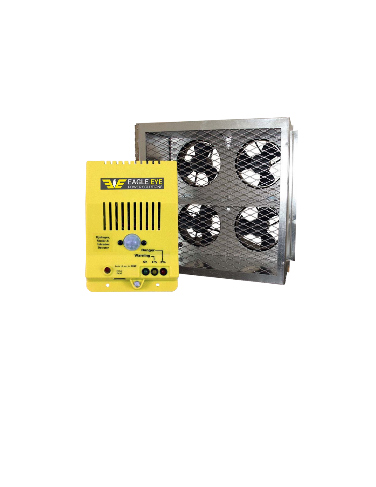
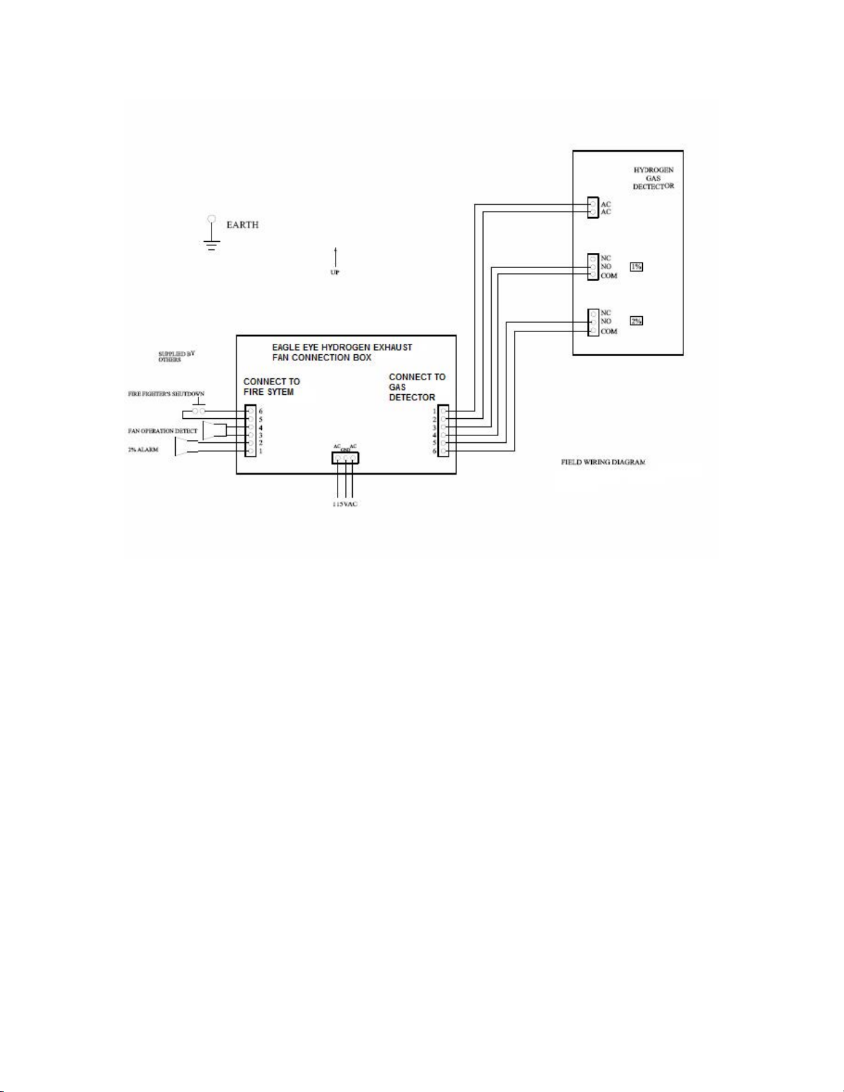
stringent. The minimum system consists of an Hydrogen Gas Detector, and a Battery
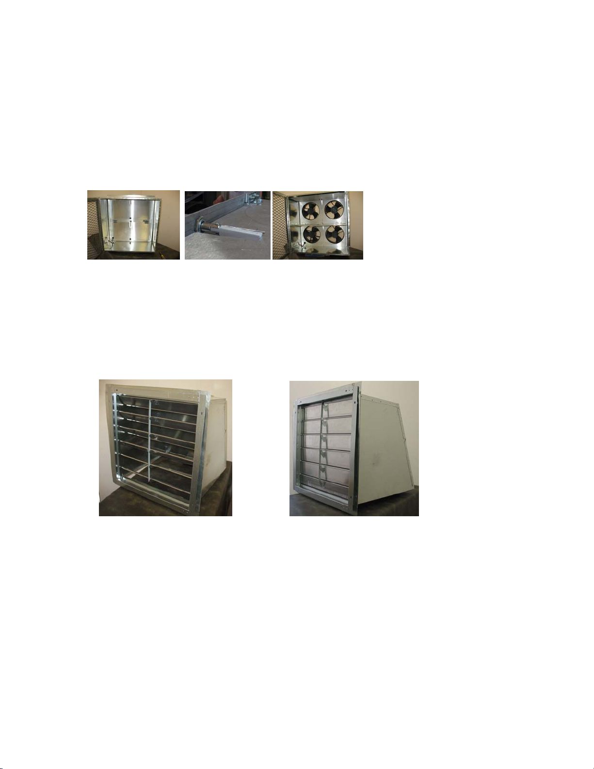
Room Forced Ventilator with Positive Airflow Shut Off, a remote firefighter’s shutdown
capability, a backflow damper, and a 2% monitored alarm. This unit complies with NEC
501.125. (B), 501.105 (1)-3 and is designed for use in Class 1 Div. 2 hydrogen
containing classified areas.
.The fan unit is compliant with the NFPA Standard on Clean Agent Fire Extinguishing
Systems (2001) Section C2.8.2.7.7 and may be used as per Sections 5.3.4, 5.3.6,
7.7.2.4.8, A5.3.6, A8.7.2 and C2.4.3.4
The fan unit is compliant with the NFPA Standard 90A Section 4.2.3, 4.2.3.1, 4.2.3.1.2,
4.2.3.2.2, and 4.2.3.3
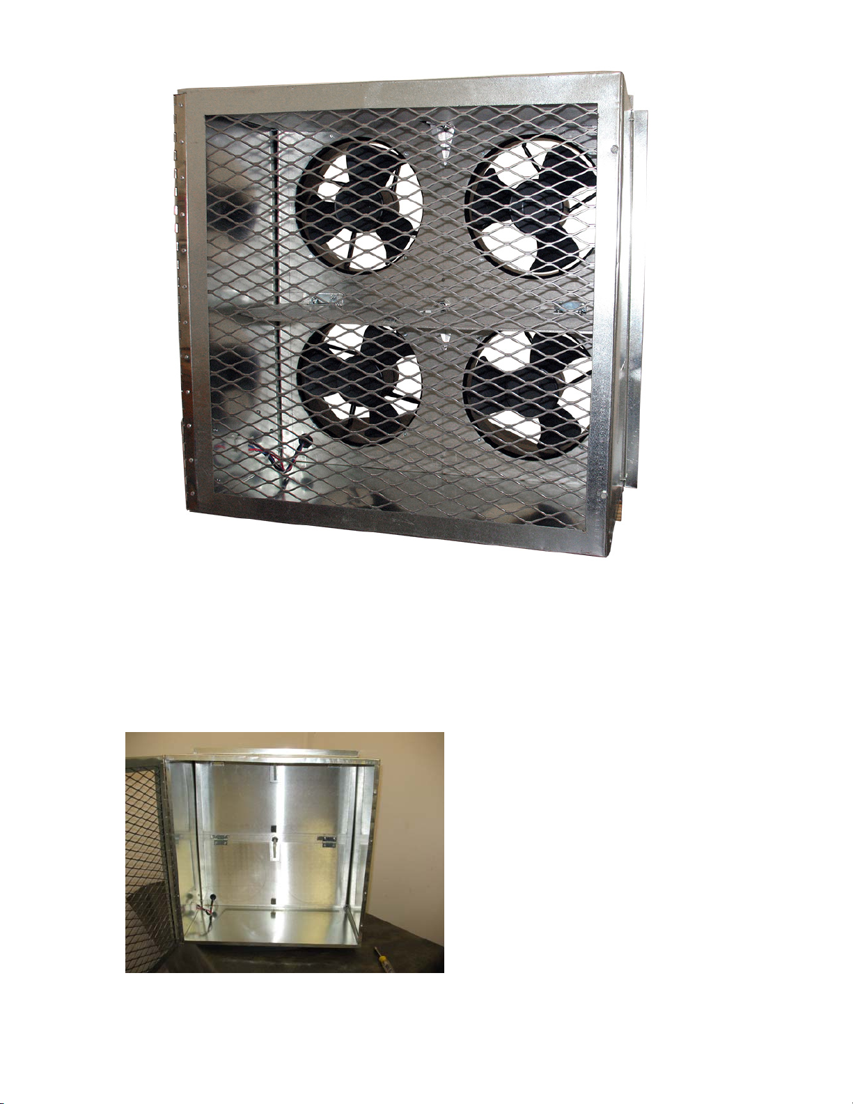
All the active component parts on the Eagle Eye Fan Battery Room Exhaust Fan With Positive
Airflow Shut Off System that are subject to testing are certified by the Underwriters’ Laboratory as
follows.
Part Number Description and Manufacturers Part # - UL number
191200 FAN DC 254X89 48V 690CFM -Orion# OD254AP-48MB - UL E17049
311011 Wire, UL1430 #24 Brown
311019 Wire, UL1430 #24 White
311060 Wire, UL1430#18 Black
311066 Wire, UL1430 #18 Blue
311072 Wire, UL1430 #16 Red
311057 Wire, UL1430 #20 Violet
151259 Receptacle, Mplex, 9 pin – Molex # 538-19-09-1099 - UL E29179
150110 Pin & Socket Connectors 9 CIRCUIT HOUSING- Molex# 15-31-1096 - UL E29179
131005 CALRAD Magnetic Switch #40-660 - UL 634
131004 DELTROL TUBULAR FRAME Solenoid, 24V MED 16 X 2.000 – UL E57982 &
E74443
130003 Power Relay, Compact PC Board, NAIS# JW1FSN-DC48V – UL E43028
Additional parts found only on the Eagle Eye Hydrogen Gas Detector
130007 Power Relay, Compact PC Board, NAIS# JW1FSN-DC12V– UL E43028
140014 Flyback Transformer, Premier Magnetics # PNY-24004 – UL E162344
150058 Phoenix Contact # 1715734

Features of the Eagle Eye Hydrogen Gas Detector
Should the concentration of hydrogen gas in the air surrounding the sensor reach 1% by
volume (10,000 ppm), the "1% Caution" yellow LED will light and the 1% internal relay
will close. Should the hydrogen gas concentration reach 2% by volume (20,000 ppm), the
"2% Warning" red LED will flash and an 80 db alarm will sound; the 1% relay will
remain closed and, if a Dual-Relay model, the 2% internal relay will close. Either relay
can activate a remote exhaust fan and/or alarm.
Dimensions: Height 7 " (17.8 cm.)
Width 4-3/4 " (12.0 cm.)
Depth 2-1/2 " ( 5.5 cm.)
Mounting: Four 3/16 " (4.5 mm.) screws
Power Requirements: 24, 48 volts dc. or 115 VAC as ordered
Relay(s): At 2% SPDT.
At 1% SPDT
Operating Temperature:
14 to 104 degrees F ( -10 to 40 degrees C)

H2 Battery Room Forced Ventilator with Positive Airflow Shut Off
If the room were to experience the release of hydrogen gas, the hydrogen gas detector
would turn on the fans when the atmosphere reached 1% hydrogen. It would sound the
alarm at 2% hydrogen. Both of these would have been well before the lean mixture of
hydrogen could ignite. During this period of time, we want the fans operating to vent the
hydrogen gas.

In operating mode
If a thermal event occurs and proceeds into a conflagration, we want the fans off and the
Positive Airflow Shut Off closed. This will prevent the air passage through the fan from
acting as a chimney and drawing oxygen rich fresh air into the burning room.
After Positive airflow shut off

When the Positive Airflow Shut Off is activated by the firefighter pulling the Emergency
Fan Stop switch, air pressure from the fans, and gravity, and a spring, will act to close the
positive shut off doors and keep them closed. A red LED at the junction box will come
on. The Positive Airflow Shut Off must be manually reset to prevent inadvertent reset in
an actual shut off event.
To reset, Open the Positive Shut off System switch. Remove the front screen. Lift the
doors up. Reset the latches. Then close the front screen.
Positive shut off doors closed Latch Doors reset
Louvered dampers on the exterior of the unit will prevent domestic air from escaping
from the room during non-operation. The fans will blow these louvered dampers open
and gravity will close them. These louvered dampers do add a restriction to the airflow
and will decrease the CFM somewhat.
Louver open Louver closed
Installation
The battery room ventilator unit comes as three separate pieces. The unit that is in the
battery room, is 24" x 24" square. To accommodate airflow, and to service the unit a
clearance of 4 feet is recommended from the wall in front of the unit. There is a flange
that is factory adjustable but normally is located 6 inches from the back of the unit. If the
wall is made in the concrete block or a concrete wall, the unit is attached to the wall by
others using normal fasteners. The second part of the unit consists of a louvered damper
and third is a jack which provides environmental protection for the outside of the unit.

The damper- jack is affixed to the outside wall with normal fasteners by others. It
measures 24 inches square and needs an outside clearance of 30 inches. A one inch flange
is provided to attach the unit and is in addition the listed dimensions.
There are two different styles of wall jack available. There is a standard wall jack, and an
optional 90° wall jack where there is a high probability of heavy mechanical damage to
the outside wall of the building.

If the unit is an Exhaust Fan the louvers must be turned to let air out. If the unit is a
Supply Fan the louvers must be turned to let air into the room. It can be positioned either
way. So, the installer must understand the airflow direction. Fan Units come from the
factory with the fans mounted in the direction needed for proper airflow. Louvers used
with Supply Fans have a spacer to provide room for louver movement. The spacer, louver
and rain hood come from the factory as an assembly. It is ready for installation. The
louver is the only installation difference.
Louver set up for Exhaust Fan Louver set up for Supply Fan
A Control Box is provided to connect Power, Return, Signaling from the HGD Sensor,
Dry Contact inputs to activate the Positive Airflow Shut Off, and Case Ground. This box
may be factory relocated to either side, or the bottom of the unit.

Electrical Installation
Test
After the system is powered up it should be tested. Push the test button on the first
hydrogen gas detector. The system will perform a self-diagnostic, and then turn on the
yellow LED. At this time, the fans should also activate and the fan operation detect
relay, if installed, will close. After a few seconds the red LED will be activated. This
should also activate the 2% alarm in the emergency control system supplied by others.
After you are satisfied with the first hydrogen gas detector, press the test button on each
successive hydrogen gas detector in the loop. It is also possible to activate the system by
exposing it to butane. Butane is inexpensively available in small butane operated
cigarette lighters. Without lighting the cigarette lighter, squirt the gas on the hydrogen
gas detector. This should activate the fans and turn on the 2% alarm. Caution: It is
sensitive to butane in order to test the sensor. This is no substitute for a butane sensor. If

you wish to test for butane, contact Eagle Eye. Also note this hydrogen gas detector
will not false alarm on smoke or carbon monoxide. It tests for hydrogen only.
Test the positive shut down control. The doors will be shipped in the closed position.
When you install the fan, reset the doors by lifting them up and latching them in place.
Make sure the fan is powered up. Close the positive shut down control contacts by
pulling the Firefighter’s Emergency Fan Stop. The doors should drop. Reset the
Firefighter’s Emergency Fan Stop. Reset the doors and close the screen. The unit is now
ready for use.
Table of contents
Popular Gas Detector manuals by other brands

RKI Instruments
RKI Instruments GX-86A instruction manual

Evikon
Evikon PluraSens E2658-LEL user manual

SENKO
SENKO SI-100 manual

Perry Electric
Perry Electric 1GA50917MET/P Installation and operating instructions

AKO
AKO AKO-575744NR quick guide

UE
UE VANGUARD WirelessHART TCD50H1A Installation and maintenance instructions