Heathus OMD User manual

1
OMD™ USER’SOMD™ USER’S
OMD™ USER’SOMD™ USER’S
OMD™ USER’S
Manual
Heath Consultants Incorporated
Houston, TX
713/844-1300
Fax: 713/844-1309
1-800-HEATH-US
www.heathus.com Heath....Leadership, Innovation, Performance
Then, Now and Tomorrow
RevD

2

3
TABLE OF CONTENTS
SPECIFICATIONS ............................................................................5
CHAPTER I
OVERVIEW ......................................................................................7
CHAPTER II
INSTALLATIONPROCEDURE ...................................................... 10
Crossbar Installation ......................................................................10
Additional Notes On Crossbar Installation..................................... 11
Power Box Installation ................................................................... 12
Cable Assemblies Installation ........................................................13
Display Installation .........................................................................14
Display Connectors ........................................................................15
Vehicle Grounding Strap ................................................................15
Protective Cage..............................................................................16
CHAPTER III
OPERATING PROCEDURE ...........................................................18
Start Up..........................................................................................18
Display Function.............................................................................20
HOLD ........................................................................................20
LIGHT........................................................................................21
SAMPLE....................................................................................22
PPM Range....................................................................................23
Alarm Set Point ..............................................................................25
Error Messages..............................................................................26
Shut Down......................................................................................27
CHAPTER IV
ALIGNMENT PROCEDURE...........................................................28
Lamp Alignment .............................................................................29
Receiver Alignment ........................................................................30
CHAPTER V
CALIBRATIONCHECK .................................................................31
Verifying Calibration With Internal Cell ..........................................31
Verifying Calibration With External Cell .........................................32

4
CHAPTER VI
MAINTENANCEINFORMATION...................................................34
General .........................................................................................34
Recommended Spare Parts..........................................................34
Troubleshooting.............................................................................34
CHAPTER VII
SERVICEINFORMATION .............................................................37
Warranty and Warranty Repairs ....................................................37
Customer Assistance and Service Locations ................................38
Appendix A
SURVEY PROCEDURES - MOBILE OMD™ ................................40
Appendix B
DRAWINGS...................................................................................55
USINGADOBE ACROBAT READER ............................................60

5
SYSTEM SPECIFICATIONS
OMDTM System Specifications
Configuration: Double - ended
Sensitivity: 1 PPM / meter CH4
Measurement Range: 1 to 200 PPM
Accuracy: ± 10% (1 to 100 PPM range)
± 20% (100 to 200 PPM range)
Above 200 PPM = Not relatively
accurate
Display Ranges: 10, 30 and 90 PPM
Self - test: During boot – up
Calibration/Test: Via operator, self - contained
Calibration: Via RS-232 through software
Base - Line Compensation: Via RS-232 through software
Display: Back-lit 2" x 6" graphics LCD,
adjustable contrast
Operator Interface: Sealed membrane switch overlay
Operator Alarms:
Signal: High pitch audible with
adjustable set point, pitch
increases with concentration.
Adjustable volume.
Error: Low pitch audible with
adjustable set point
Error alarms
provided for: Warm-up,LowLight,
CommunicationFailure&
Batterylow
SystemPower: 72 Watts @ 12 VDC
System Voltage: 12 - 16 VDC
NOTE: To avoid damage to the OMD™power box, the fuse
must be removed prior to charging or jumping the battery
in the survey vehicle!

6
SYSTEM SPECIFICATIONS
SystemWeight:
External Sub - Systems: 17 pounds
Power Box 6 pounds
Internal Display 3 pounds
Cables 4 pounds
CrossbarAssemblyLength: 63.25, 32, 51.25in. ±2in.
MechanicalMounting: Strutbracketmount
Installation Time: 2 hours, typical
External Housing Rating: NEMA 3S and IP 54
Display Housing Rating: Spill proof
External Sub -
System Materials: Aluminum and plastic
Environmental PCB Control: Conformal PCB coating
Operating Temperature
Range: - 22°F to 122°F
Operating Humidity Range: 5 to 100 % RH, non-condensing

7
Chapter I
OVERVIEW
The Optical Methane Detector (OMD™), is the first of the
“next generation” leak detection systems which address the
high cost presently associated with leak surveying. This new
technology combines sensitivity, selectivity and speed through
the combined use of optics and electronics. The OMD is
mounted on the front of a survey vehicle and detects the pres-
ence of methane in air. It provides for the detection of gas
leaks down to 1 part per million (PPM). It has no moving parts
that will prevent the instrument from operating. It requires no
support gases and is virtually maintenance free.
Based on the absorption of infrared (IR) radiation by methane,
the OMD consists of an IR light source directed at an IR
optical detector. These two are spaced approx. four feet apart
across the width of the vehicle. An optical filter in front of the
detector transmits primarily methane specific IR wavelengths
from the light source. In the absence of methane, these wave-
lengths are unaffected and produce a steady output signal from
the detector. When the vehicle passes through a plume of
natural gas, methane in the plume will absorb some of the IR
light reaching the detector. As a result there is a sudden de-
crease in IR light at the detector causing a decrease in detector
output. This change in detector output is transmitted to the
display panel located next to the vehicle’s driver and becomes
a signal, both audio and visual. Gas concentration is calculated
in the OMD by converting the methane to light ratio to PPM.
The data is displayed in both analog and digital form. The
analog display appears as a peak scrolling across the display
screen. The OMD will also detect other hydrocarbons such as
ethane and propane but with less than half the sensitivity.

8
TheOMDoperatesreliablyunderavarietyof environmental
conditions including dry weather, snow, ice and temperatures
from-22° F to+122° F. Itssensitivity,calibration or response|is
notaffectedbysmall fluctuations in thelightbeamorbyreasonable
amountsofdust,or snow ontheoptics. Aninternalcalibrationtest
cellisincludedso the operatorcanverifyproperoperationfrom the
vehiclecabat any timebefore,duringor after aleaksurvey. An
InstallationMountingKitisavailableformountingtheOMDtothe
frontofavehicle. Allinterconnectingcablingisprovidedwith the
OMDincludingthecableto obtain powerto operatetheinstrument
fromthesurveyvehicle 12 voltbattery. AnRS232 port isincluded
wherebya personal computermaybe connected toacquire and
save the survey data with the appropriate software.
Depending on local meteorological conditions, a given amount
of gas escaping from the ground will produce a plume that
varies in size and uniformity of concentration levels. The
plume, of its very nature, defies quantification by fixed or
moving detectors. Regardless of these uncertainties, it is of
paramount importance to be able to detect gas when gas is
present. Concentration levels of the measured gas are of
interest, but are of secondary importance. Consequently, the
ability of a detector to detect the plume with accuracy and
precision is not as important as its ability to do so with good
sensitivity (or a low detection limit) and with a minimum of
false alarms.
There are two kinds of false alarms: false negatives and false
positives. False negatives occur when a leak is missed. The
detector is saying there is no gas present when, in fact, a leak
was present but undetected. False positives occur when the
detector says that a gas leak is present when it really is not.
Examplesoffalsepositives experienced includethedetectionof
OVERVIEW

9
autoexhaust and swamporsewer gas. Due totheselectivity of the
OMD,falsepositivescausedbyauto exhaust are greately mini-
mized.
NEW
Experienced operators should use their discretion. Operators
should take into account that the wind must be favorable,
towards the path of the OMD light bar, to obtain the optimum
results. Increased speed from FID survey comes from the
instantaneous response of the OMD; however, there are a
variety of factors to consider such as, legal limits, terrain and
inclement weather for the OMD operation. Please refer to
the GPTC Guide for Transmission and Distribution Piping
Systems: 1998-2000 Guide Material Appendix G-192-11
Section 4 Leak Detection, 4.4 Leakage surveys and test
methods (a) Surface Gas Detection Survey. Part (3) Utiliza-
tion. The use of this survey method may be limited by ad-
verse conditions (such as excessive wind, excessive soil
moisture or frost or surface sealing by ice water). The survey
should be conducted at speeds slow enough to allow an
adequate sample to be continuously obtained by placement of
equipment intakes over the most logical venting locations,
giving consideration to the location of the facilities and any
adverse conditions which might exist.
OVERVIEW

10
Chapter II
INSTALLATION PROCEDURE
It is virtually impossible to predict the exact installation proce-
dure for every different type of vehicle on the market. There
are some details that will have to be worked out on the spot
with your particular vehicle and here are a few ideas to con-
sider.
There are five parts to consider when installing the OMD: 1)
The crossbar assembly, 2) The power box, 3) The cable assem-
blies, 4) The display unit, and 5) Vehicle Grounding Strap.
Crossbar installation:
The OMD components are pre-aligned at the factory and
should not require re-alignment when the system is installed on
the vehicle. It is, however, important that the u-bolts be at-
tached in such a way that they do not bend the support rod.
The u-bolts should be tight enough to hold the OMD crossbar
securely in place, but not so tight as to distort the crossbar. If
that happens, re-alignment may be required. We recommend
using only two insulated u-bolts to mount the OMD crossbar to
minimize the possibility of distorting the crossbar. The follow-
ing procedure will generally work best.
For your convenience, we have put together an OMD mounting
kit, which includes strut channels, shelf brackets, u-bolts and
mounting hardware (Heath P/N 2510651).
Use two strut channels that are approx. 24” long each (Heath P/
N 2510652). These strut channels are mounted vertically to
the front bumper of your vehicle, parallel to each other and
approx. three feet apart. It is most fortunate if you have a front
bumper that is relatively flat vertically, in which case the strut
channels can be mounted directly to the bumper. If the bumper

11
INSTALLATION
is not flat, some other type of brackets, supports, etc. will need
to be used to attach the strut channels to the front of the ve-
hicle. Mount the two strut channels approx. one-foot from the
ground to the bottom of each strut channel. A drawing is
included in Appendix A.
Once the strut channels are mounted, use standard strut chan-
nel shelf brackets (Heath P/N 2510654) to mount to the strut
channels with two bolts (Heath P/N 2510655) and channel-nuts
(Heath P/N 2510653) each. The OMD crossbar can then be
attached to the shelf brackets with the insulated u-bolts pro-
vided (Heath P/N 2510657).
Once this installation is complete, the height of the OMDcan
easily be adjusted by loosening the bolts attaching the shelf
brackets to the strut channel and sliding the OMD up or down
to the desired position. In addition, the shelf brackets can be
mounted facing upward so that the OMD can be extended
another 10” up toward the hood. The shelf brackets can also
be mounted downward so that the OMD can be extended
another 10” down toward the ground.
Additional Notes On Crossbar Installation:
One of the most important points to consider when installing
the crossbar assembly is air- flow. Unlike the flame ionization
technology, which has a vacuum pump to bring the sample to
the analyzer, the OMD relies strictly on the flow of gas through
the optical path. Therefore, it is of the utmost importance that
you install the OMD in such a way as to allow the gas to flow
continuously through the optical path. It is important that you
don’t configure your mounting brackets in a way that creates a
dead space thus preventing gas from flowing freely across the
optical path. A drawing illustrating this problem is included in

12
INSTALLATION
Appendix A at the end of this manual. Many vehicles have
vents below the bumper to allow airflow into the engine com-
partment. This is a good place for the optical path. If you
attach the OMD crossbar at bumper height, then hang the
optical path slightly below the bumper and gas will flow across
the optical path then on into the engine compartment.
The best location for your OMD crossbar assembly will vary
from vehicle to vehicle. However, one principle remains the
same, install the crossbar in such a way as to allow gas to
freely flow across the optical path.
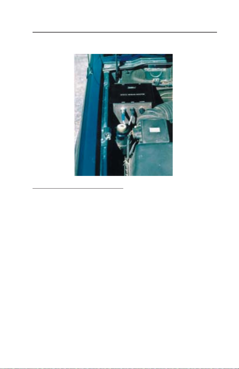
Power box installation:
The original suggestion was if the vehicle had sufficient room,
that the Power Box should be mounted under the hood. This
reasoning was to eliminate the need for routing multiple cables
into the vehicle cab. However, field experience indicates that
in some instances, heat from the vehicle engine coupled with
high ambient temperatures can result in Power Box failures.
The current suggestion is to mount the Power Box inside the
cab of the vehicle. The first thing to consider when mounting
the power box inside the cab is cable length. The standard
cables are at least long enough to mount the power box directly
behind the front seat on most vehicles. If you desire to mount
it further back, check the length from the desired mounting
position to the OMD crossbar assembly mounted in front of the
front bumper.
After determining where you want to mount your power box,
simply place the box in the desired spot and mark through the
mounting holes on the ears of the box with a pencil. Drill
starter holes, then attach the box with four # 8 x ½” sheet metal
screws.
13
Cable assemblies installation:
Each cable assembly for the OMD is uniquely constructed so
that it cannot be connected to the wrong mating connector.
First, you will need to determine which cable goes where. If
you mounted the power box under the hood, then you will only
need to route the display cable either through the firewall or
through the floorboard. If you mounted the power box inside
the cab, you will need to route the other three cables into the
cab as well.
INSTALLATION
Unless a hole large enough to route the cabling through already
exists, you will need to drill one. A hole approximately 1-1/8
inches in diameter should be sufficient to route one or three
cables. A 1-1/8 inch rubber grommet should be used in this
hole to protect the cables from damage. A 1-1/8 inch rubber
grommet may be purchased from Heath as P/N 2510686.

14
INSTALLATION
Whenroutingcablesfromthecab to the frontofvehicle,fastenthe
cablestofixed parts ofyourvehicle with tiewraps. Tiewraps are
available from Heath as P/N 9996350 for 4” (per 1,000) and P/N
0419180for 8”(each). Be sure toroute cablesaway from exhaust
componentsandshiftlinkages.
TheOMDrequires six amperesofcontinuouscurrent. So connect
thesystem power cabletothe vehicle’sbattery. Donot connect
thesystempowercable to thecigarettelighteroranywhereelse
thatis not ratedforat least sixamperes. Whenconnecting power,
polaritymustbe observed. If thepositiveand negative leadsare
reversed,thefusewillblowimmediately. Theredwireshouldbe
connectedtothepositive terminal andtheblackwireconnected to
thenegativeterminal ofthebattery.
Note:
Connectthe battery cableup last. Be surethat the receivercable is
connectedpriorto making thebatteryconnection. Damagetothe
electronicsmayoccurifnotproperlyconnected
Displayinstallation:
Therequirementsforinstallingthedisplayincludemountingthe
displayatan operatorfriendlyheightandpositionandthenplugging
inthedisplay cable. A floorboardmountingpedestalor adash-
boardconsoleare two possiblemountingmethods. Thesetypes of
devicesareavailable fromsuppliersofcellularphoneequipment.
15
Vehicle Grounding Strap
A vehicle-grounding strap is included in the OMD mounting
kit. The purpose of this strap is to prevent the buildup of an
Electro-static charge, thereby preventing any condition of
Electro-static discharge between the operator and the display
unit, which can cause a reset condition of the display unit. The
ground strap mounting location on the vehicle is at the discre-
tion of the customer. To ensure proper operation, however,
certain conditions need to be observed.
·Ground strap must be mounted to the vehicle chassis. Avoid
mounting to any surface that is painted or plated.
·Ground strap should have a minimum of three inches of the
strap in contact with the surface being traveled over.
INSTALLATION
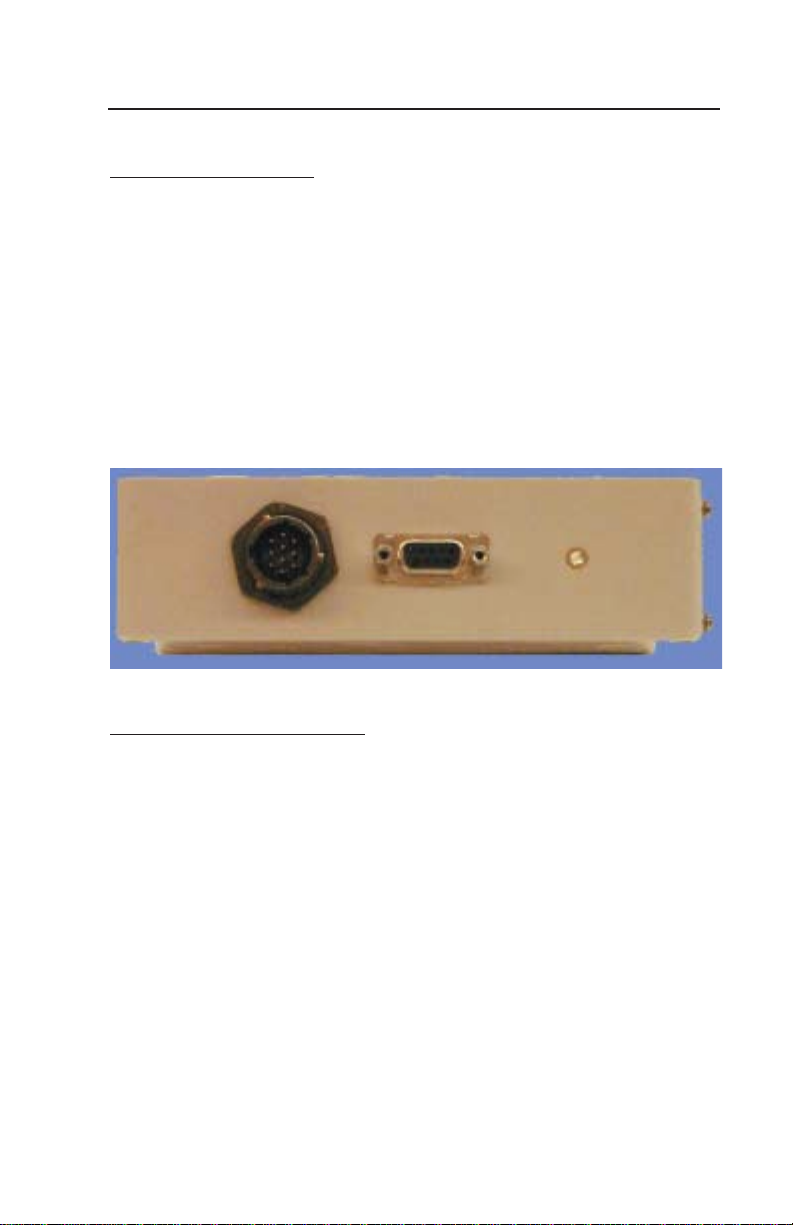
DisplayConnectors:
There are three connectors on the side of the display box. The
first is for the system cable which comes from the power box
connector marked “Display.” Next is the RS-232 connector,
which is to connect a computer for data logging, etc. Then
there is a 1/8” phone jack for connecting an external speaker.
When a phone plug is plugged into the speaker jack the inter-
nal alarm speaker is disabled.

16
·Verify that the mounting location of the strap will not cause
it to come in contact with any rotating parts, such as drive
wheels or drive shaft.
NOTE: Ground strap mounting hole is .475”ID and strap length
is 30”.
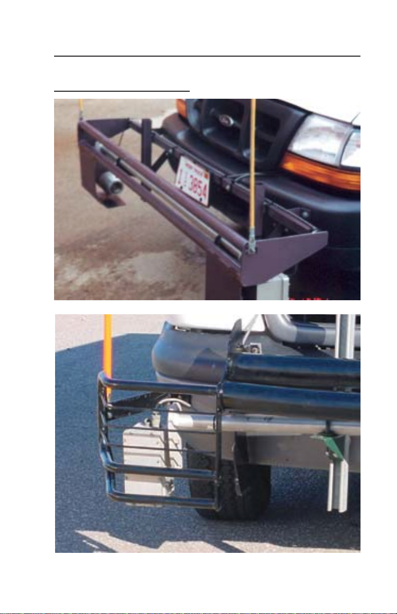
Protective Cage
Because the main part of the OMD is located on the front
bumper of the survey vehicle, it is in danger of being damaged
due to the possibility of bumping into something. We recom-
mend that a cage be built around the OMD to protect it.
It would be nearly impossible to build one cage that would fit
on every type of vehicle used for mobile surveying. Therefore
Heath does not offer one at this time. We recommend that you
take your vehicle to a local fabrication shop to custom build
one for your vehicle.
Following are a few photos of typical protective cages presently
in use.
INSTALLATION
17
Photos of Protective Cages
INSTALLATION

18
Chapter III
OPERATING PROCEDURES
Start Up:
1) Turn on the SYSTEM POWER by pressing the “SYSTEM
POWER” button. The red LED above the SYSTEM POWER
button will light up and a message will appear on the screen
stating, “PUSH DISPLAY FUNCTION TO CONTINUE.”
Press the Display Function button twice to enter the normal
operating mode.
If the system has been off for more than several seconds, a
“SYSTEM WARMING UP,” message will be displayed. The
systemwillrequireuptoapproximately15minutesbeforeabeep
willbeheard and amessageprompting the operatorto,“TURN
ONTHELIGHTSOURCE” will be displayed.
2) Turnon theLIGHT SOURCEif not doneso alreadyby press-
ingthe“LIGHT SOURCE” button. TheredLED above the
LIGHTSOURCEbuttonwilllight up and normaloperationof
thesystemwillbegin. Ifthevehicle will be turned offfora
break, turn off the LIGHT SOURCE to save the automobile
battery, while keeping the System Power on. A message
prompting the operator to turn on the LIGHT SOURCE to
resume operation will be displayed. System current con-
sumption with the light is approximately five amperes
while system current consumption without the light is less
than one and one half amperes, which can be sustained by a
good automobile battery, without the use of the engine, for
at least 12 hours without causing starting problems. How-
ever, extreme cold conditions may require the vehicle to
remain running as battery capacity drops significantly with
reducedtemperature.
3) Allowtimefortheinstrumenttostabalize. Thismaytake 45 to

19
OPERATING PROCEDURES
60minutes. Thesystemis stable whenthePPMreadings
becomeconsistant.
4) Press theCALIBRATIONTEST button. Thered LED above
theCALIBRATIONTESTbuttonwilllightupandasmall
internalcellcontainingmethanewillbeplacedintheoptical
path. Thistestcellwillremaininthelightpathforapproximately
fivesecondsunlessthebutton is held down. Afterfiveseconds
thecellwillreturn to its normalpositionandtheredLEDwill
turnoff. Theincreaseinmethaneabovethe background should
beshownon the calibrationdatasheetthat was shippedwith
yourinstrument. Inotherwords,ifthe baseline on thedisplayat
thetimeofthe calibration is2PPMandthe calibration data
sheetindicatesthat thecalibrationcellcontainstheequivalentof
15PPM of gas,an increase insignal level from2 to 17PPM
willbeexpectedwhenthe CALIBRATIONTEST buttonis
pressed. Somedeviationfromthis exact numberisacceptable
asindicated bythe range onthe datasheet. It is goodpractice
tooccasionallypresstheCALIBRATIONTESTbuttonduring
thedailyoperationofthesystemto insure that the systemis
operatingproperly.
The concentration of the gas within this test cell is actually
much higher than the reading listed on the data sheet. The
reading obtained from this test cell is equivalent to the read-
ing of a gas cloud that fills the entire volume within the light
path, that is, the volume between the lens on the lamp assem-
blyandthelensonthe receiver assembly.
5) Set the Audible ALARM SETPOINT by pressing either the
ALARM SETPOINT UP or DOWN button. The audible
alarm will be sounded if the present methane level is greater
than the ALARM SETPOINT level. Holding either the up or
down ALARM SETPOINT button will enable the auto scroll

20
OPERATING PROCEDURES
6) Set the SPEAKER VOLUME of the alarm to the desired level
by pressing either the SPEAKER VOLUME INCREMENT
or DECREMENT button to raise or lower the SPEAKER
VOLUME. Holding either the up or down SPEAKER VOL-
UME button will enable the auto scroll feature. If needed,
press the CALIBRATION TEST button to introduce a gas
alarm.
7) Adjust the CONTRAST to the desired level by pressing either
the CONTRAST UP or DOWN button to raise or lower the
CONTRAST control to maximize the visibility of the display.
Holdingeither theupor downCONTRAST button willenable
theautoscrollfeature.
DISPLAY FUNCTION:
The DISPLAY FUNCTION has three modes- HOLD, LIGHT &
SAMPLE. These modes are entered by consecutively pressing
the DISPLAY FUNCTION button to scroll through each. Begin-
ning with HOLD, as you continue to press the button the mode
changes from HOLD to LIGHT to SAMPLE and back to HOLD
again, as indicated by the direction of the arrow.
HOLD:
This is the power up default position indicated by the line under
the word HOLD. This position will stop the updating of the
methane level vs. time. This allows the operator to inspect the
display before it scrolls off the screen. This is especially impor-
tant in one-person survey operations as the driver may hold the
display while finding a place to pull off the road. A message
prompting the operator to “PUSH DISPLAY FUNCTION TO
CONTINUE”, will be displayed. The display will be cleared
when the DISPLAY FUNCTION button is pressed again, leaving
Table of contents


