BIOPAC Systems BioNomadix Series User manual

PRODUCT SHEET
info@biopac.com
support@biopac.com
www.biopac.com
BIOPAC Hardware | BioNomadix Series | Page 1 - 26 Updated: 8.18.2020
BIONOMADIX SERIES
The BioNomadix system is a wireless, multi-channel physiological recording
platform. Its untethered design allows for nearly unlimited freedom of movement
and unsurpassed comfort, enabling subjects to easily relax into their protocol.
There are twelve different BioNomadix modules sets, each consisting of a
matched transmitter and receiver specifically optimized for desired physiological
signals. Multiple BioNomadix module sets (typically eight maximum) can be used
to create a customized BioNomadix system.
Each BioNomadix module set is capable of recording of two independent channels, with the exception of the
Accelerometer module, which records three channels.
BIONOMADIX TRANSMITTER AND RECEIVER SETS
BN-ACCL3 BioNomadix Accelerometer
BN-ECG2 BioNomadix 2-Channel ECG
BN-EEG2 BioNomadix 2-Channel EEG
BN-EGG2 BioNomadix 2-Channel EGG
BN-EMG2 BioNomadix 2-Channel EMG
BN-PPGED BioNomadix PPG and EDA
BN-GONIO BioNomadix 2-Channel Goniometry
BN-DYNEMG BioNomadix Dynamometry and EMG
BN-EOG2 BioNomadix 2-Channel EOG
BN-NICO BioNomadix Cardiac Output
BN-RSP2 BioNomadix 2-Channel Respiration
BN-RSPECBioNomadix RSP and ECG
BN-SKT2 BioNomadix 2-Channel Skin Temp
BN-STRIKE BioNomadix 2-Channel Heel/Toe Strike
BioNomadix BN-GYRO-75 and BN-GYRO-300 Angular Rate Sensors are discontinued items.
BIONOMADIX TRANSMITTER ONLY
BN-ACCL3-T Accelerometer
BN-ECG2-T 2-Channel ECG
BN-EEG2-T 2-Channel EEG
BN-EGG2-T 2-Channel EGG
BN-EMG2-T 2-Channel EMG
BN-PPGED-T PPG and EDA
BN-GONIO-T Goniometry
BN-DYNEMG-T Dynamometry and EMG
BN-EOG2-T 2-Channel EOG
BN-NICO-T Cardiac Output
BN-RSP2-T 2-Channel Respiration
BN-RSPEC-T RSP and ECG
BN-SKT2-T 2-Channel Skin Temp
BN-STRIKE-T 2-Channel Heel/Toe Strike
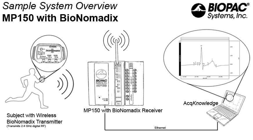
Click to view a BioNomadix System Diagram.
BIONOMADIX LOGGER (BN-LOGGER) Get the real-world data your application demands!
BioNomadix Loggers wirelessly record physiological data as subjects freely and naturally live their lives—record
from up to three dual-channel wearable BioNomadix Transmitters*plus a built-in accelerometer. Sync the
BioNomadix Logger with GPS for a correlation between physiological and location data.
Use as a stand-alone system with AcqKnowledge or combine with BioNomadix Receivers and a computer
running AcqKnowledge:
•Sync Transmitters to the Logger mode for remote data logging.
•Combine Transmitters with BioNomadix wireless Receivers to
operate in the lab for real-time telemetry.
The compact Logger device provides a color display for visual
feedback, speaker for auditory feedback, vibration for haptic feedback,
voice journal for participant comments, event markers, and alarms.
Includes micro-USB to USB cable for charging/data transfer, AC
Charger and belt case.
* Existing BioNomadix devices require a firmware upgrade to be
compatible with Loggers—see BN-TX-UPG online for details.
NOTE: BioNomadix Logger requires AcqKnowledge software version 4.4.1 or higher.

PRODUCT SHEET
info@biopac.com
support@biopac.com
www.biopac.com
BIOPAC Hardware | BioNomadix Series | Page 2 - 26 Updated: 8.18.2020
BioNomadix Logger Specifications
Weight: 121.2 grams
Transmitter: Ultra-low power 2.4 GHz bi-directional digital RF transmitter
Dimensions: 9.42 cm x 5.76 cm x 2.3 cm
Rate: 2 kHz, maximum
Screen: Color, 6 cm diagonal
RF reception range: 1 meter (line of sight, approx.)
Memory: 32 GB
Charger: Integrated USB charger with AC wall adapter BN-LOG-CHRG
Battery: 1800 mAh Lithium-ion
Operating time: 24 hours (recording)
Compliance: FC, CE, IC, VCCI -FCC Part 15 B FCC ID: ZWIBNXT1, IC: 9901A-
BNXT1
Time to full charge: ~12 hours
Built-in Accelerometer: X, Y, Z –axes; rate 100-400 Hz; Range: ±2-16 G
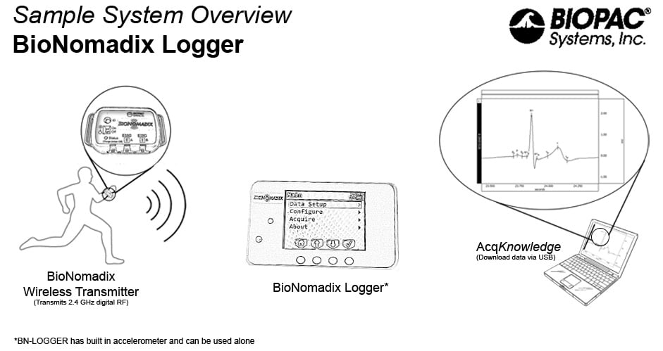
Click to view a BioNomadix Logger System Diagram.
BIONOMADIX ELECTRODE LEAD SET (use with wireless and Smart Amplifiers)
BN-EL15-LEAD2 Electrode Lead 2 x 15 cm to BioNomadix or 100D Smart Amps
BN-EL15-LEAD3 Electrode Lead 3 x 15 cm to BioNomadix or 100D Smart Amps
BN-EL30-LEAD2 Electrode Lead 2 x 30 cm to BioNomadix or 100D Smart Amps
BN-EL30-LEAD3 Electrode Lead 3 x 30 cm to BioNomadix or 100D Smart Amps
BN-EL45-LEAD2 Electrode Lead 2 x 45 cm to BioNomadix or 100D Smart Amps
BN-EL45-LEAD3 Electrode Lead 3 x 45 cm to BioNomadix or 100D Smart Amps
BN-EL50-LEAD2 Electrode Lead 2 x 50 cm to BioNomadix BN-NICO
BN-EL50-LEAD4 Electrode Lead 4 x 50 cm to BioNomadix BN-NICO
BN-EDA-LEAD2 EDA Electrode Lead 2 x 15 cm to BioNomadix BN-PPGED or Smart Amplifier EDA100D
BN-EDA25-LEAD2 EDA Electrode Lead 2 x 25 cm to BioNomadix BN-PPGED or Smart Amplifier EDA100D
BN-ADAPT-2 Adapter 2 x 10 cm for connecting 1.5 mm Touchproof leads to BN Transmitter
BN-ADAPT-3 Adapter 3 x 10 cm for connecting 1.5 mm Touchproof leads to BN Transmitter
BIONOMADIX TRANSDUCERS (use with wireless and Smart Amplifiers)
BN-PULSE-XDCR Pulse Transducer for BioNomadix BN-PPGED or Smart Amplifier PPG100D
BN-PULSEEAR-XDR Pulse Earclip Transducer for BioNomadix BN-PPGED or Smart Amplifier PPG100D
BN-RESP-XDCR Respiration Transducer for BioNomadix BN-RSP2, BN-RSPEC, or Smart Amplifier RSP100D
BN-TEMP-A-XDCR Skin Temp Skin Transducer for BioNomadix BN-SKT2 or Smart Amplifier SKT100D
BN-TEMP-B-XDCR Fast-Response Temp Transducer for BioNomadix BN-SKT2 or Smart Amplifier SKT100D
BN-STRIKE-XDCR Heel-Toe Strike Transducer for BioNomadix BN-STRIKE
BN-GON-110-XDCR Twin-axis Goniometer Transducer for BioNomadix BN-GONIO
BN-GON-150-XDCR Twin-axis Goniometer Transducer for BioNomadix BN-GONIO
BN-TOR-110-XDCR Single-axis Torsiometer Transducer for BioNomadix BN-GONIO
BN-TOR-150-XDCR Single-axis Torsiometer Transducer for BioNomadix BN-GONIO
BN-GON-F-XDCR Single-axis Goniometer Transducer for BioNomadix BN-GONIO
BIONOMADIX ACCESSORIES
Straps
BN-STRAP-20 BioNomadix Strap 20 cm x 25.4 mm
BN-STRAP-33 BioNomadix Strap 33 cm x 25.4 mm
BN-STRAP-76 BioNomadix Strap 76 cm x 25.4 mm
BN-STRAP-137 BioNomadix Strap 137 cm x 25.4 mm
EEG Caps (for BN-EEG2)
BN-EEGCAP-SYS BioNomadix 10/20 EEG Cap System
BN-CAP-SMALL BioNomadix EEG Cap –Small (50-54 cm)
BN-CAP-MEDIUM BioNomadix EEG Cap –Medium (54-58 cm)
BN-CAP-LARGE BioNomadix EEG Cap –Large (58-62 cm)
Chargers
BN-BAT-CHRG for Transmitters,–full charge lasts 72-90 hours, full charge in approximately 1 hr.
BN-LOG-CHRG for Loggers –full charge lasts 24 of operation with 30 days stand-by, full charge in
approximately 12 hours. Both chargers provide a lifespan of 500 charge/discharge cycles—or 35,000 hours!
PRODUCT SHEET
info@biopac.com
support@biopac.com
www.biopac.com
BIOPAC Hardware | BioNomadix Series | Page 3 - 26 Updated: 8.18.2020
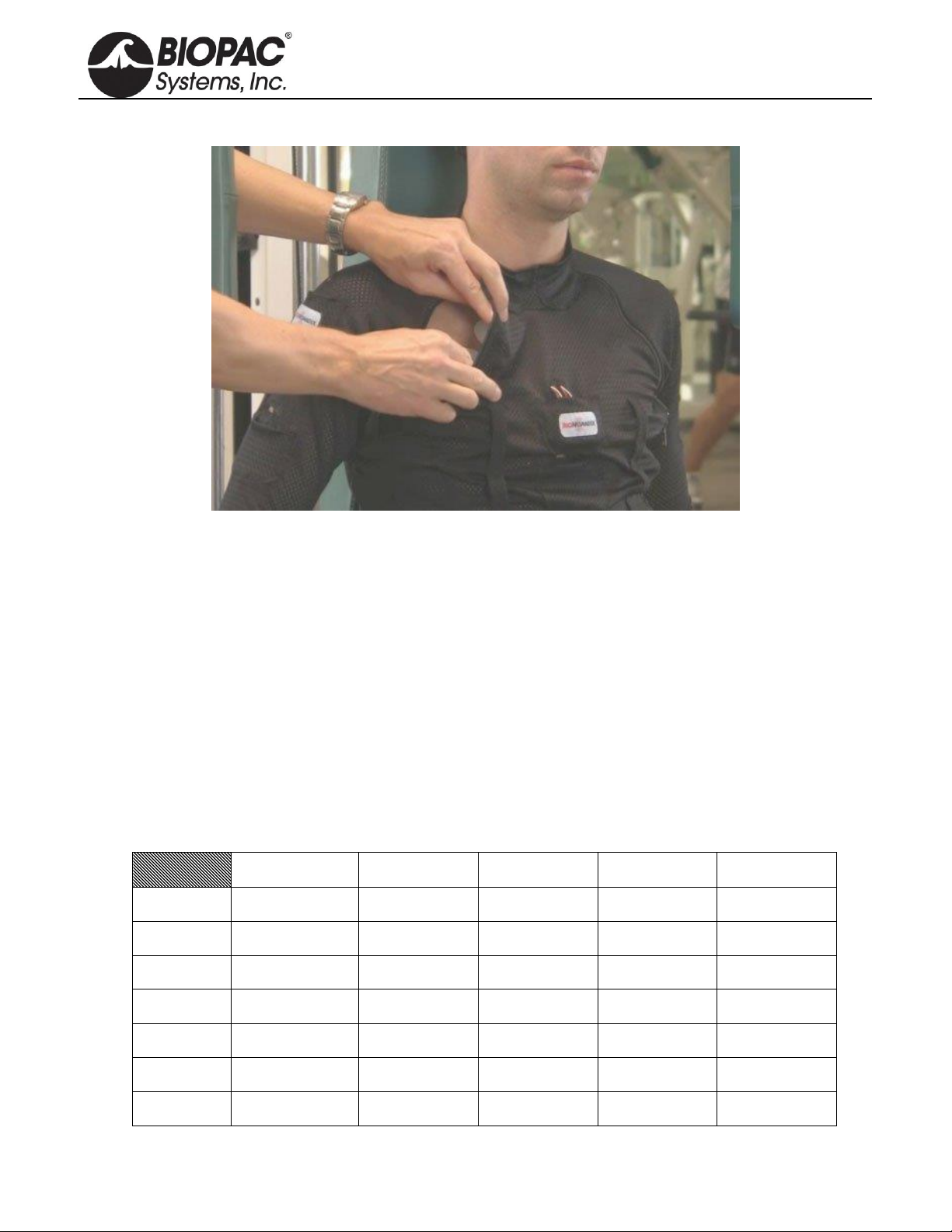
BIONOMADIX SHIRT (BN-SHIRT)
Use this stretch mesh shirt to comfortably hold multiple devices in place when subjects will have several
BioNomadix transmitters attached to their body—wear as is or under clothing. Pockets hold the transmitter and
have reinforced access slots to pass leads through for connection, plus zippers add easy access to attachment sites.
Select size so the shirt is worn tight to hold the BioNomadix transmitter and sensors in place.
The BioNomadix shirt provides a greater degree of comfort and mounting flexibility for multi-sensor studies.
The shirt allows the subject to wear the devices in natural and well balanced positions for long-term physiological
studies exercise regimes. This natural, unhindered environment significantly improves the quality of the data, and
makes it much easier for subjects to respond naturally. Available sizes, extra small, small, medium, large, and
extra large (see sizing dimensions below).
•22 pockets: 2 neck front, 2 neck back, 4 chest center, 4 back center, 2 hip front, 2 hip back, 3 left
arm , 3 right arm
•4 zippers: right front from arm to hip, left back from shoulder to hip, right and left under arm from
neck front to neck back
•4 strap bands: 4 rows of strap bands (2 loops front, 2 loops back) for RSP transducer strap
BIONOMADIX SHIRT SIZING
BN-SHIRT-XS
BN-SHIRT-S
BN-SHIRT-M
BN-SHIRT-L
BN-SHIRT-XL
Front: Chest
38.7 cm (15.25”)
40.6 cm (16”)
42.5 cm (16.75”)
47.6 cm (18.75)
52.7 cm (20.75”)
Front: Waist
29.2 cm (11.5”)
31.8 cm (12.5”)
34.3 cm (13.5”)
39.4 cm (15.5”)
43.8 cm (17.25”)
Front: Hip
28.6 cm (11.25”)
30.5 cm (12”)
33 cm (13”)
38.1 cm (15”)
43.8 cm (17.25”)
Back: Chest
44.5 cm (17.5”)
47.6 cm (18.75”)
48.9 cm (19.25”)
53.3 cm (21”)
60.3 cm (23.75”)
Back: Waist
36.5 cm (14.375”)
39.4 cm (15.5”)
45.7 cm (18”)
45.7 cm (18”)
51.4 cm (20.25”)
Back: Hip
36.2 cm (14.25”)
39.4 cm (15.5”)
45.7 cm (18”)
45.7 cm (18”)
51.4 cm (20.25”)
Back: Length
61 cm (24”)
62.2 cm (24.5”)
64.8 cm (25.5”)
67.9 cm (26.75”)
71.1 cm (28”)

PRODUCT SHEET
info@biopac.com
support@biopac.com
www.biopac.com
BIOPAC Hardware | BioNomadix Series | Page 4 - 26 Updated: 8.18.2020
BIONOMADIX BIOSHIRT (BN-BIOSHIRT)
Smart shirt simultaneously acquires ECG and Respiration data while subjects roam freely
The lightweight, comfortable BioNomadix BioShirt contains a respiration sensor and fabric electrodes to
wirelessly record both respiration and ECG while ambulatory subjects move freely and perform tasks in short or
long-term studies, in the lab, or in the real world. The shirt connects to a wireless BioNomadix BN-RSPEC
Respiration & ECG Transmitter placed in a small pocket on the front of the BioShirt—no electrodes, gels, or
wires to fuss over. Transmit data to either a stand-alone BioNomadix Smart Center, Logger or an MP160/150
System with matched BioNomadix Receiver module.
BioNomadix wireless recording and AcqKnowledge software provide a powerful, complete solution that
supports advanced analysis for applications and measurements for a variety of physiological parameters,
including: Heart rate, respiration rate, Heart rate variability (HRV), Respiratory Sinus Arrhythmia (RSA), etc.
Combine with the Logger, GPS tracker, and other wireless sensing devices for comprehensive analysis of your
subject’s experience. The Logger’s accelerometer can provide activity information, the GPS will provide a history
of a subject’s movements.
Sized separately for men and women, for a snug fit below the bust to maintain sensor contact.
BIOSHIRT SPECIFICATIONS
Attachment Features: Single-pocket Smart Shirt holds BN-RSPEC Transmitter (Respiration and ECG),
woven-in fabric electrodes
Materials: 76% Nylon/Polymid, 23% Elastane, 1% Polyester
Sizes:
(M = Male, F = Female) BN-BIOSHIRT-MS 76-82 cm (29.9-32.2”) BN-BIOSHIRT-FXS 65-69 cm (25.5-27.1”)
BN-BIOSHIRT-MM 83-89 cm (32.6-35.0”) BN-BIOSHIRT-FS 69-73 cm (27.1-28.7”)
BN-BIOSHIRT-ML 90-96 cm (35.4-37.8”) BN-BIOSHIRT-FM 73-77 cm (28.7-30.3”)
BN-BIOSHIRT-MXL 97-103 cm (38.2-40.5”) BN-BIOSHIRT-FL 77-81 cm (30.3-31.9”)
BN-BIOSHIRT-MXXL 104-110 cm (40.9-43.3”) BN-BIOSHIRT-FXL 81-85 cm (31.9-33.5”)
BN-BIOSHIRTM3XL 111-117 cm (43.7-46.0”) BN-BIOSHIRTF2XL 85-89 cm (33.5-35.0”)
BN-BIOSHIRTM4XL 118-124 cm (46.4-48.8”) BN-BIOSHIRTF3XL 89-93 cm (35.0-36.6”)
BN-BIOSHIRTF4XL 93-97 cm (36.6-38.1”)
Care Instructions: Wash separately, line dry, no fabric softener

PRODUCT SHEET
info@biopac.com
support@biopac.com
www.biopac.com
BIOPAC Hardware | BioNomadix Series | Page 5 - 26 Updated: 8.18.2020
SETUP OVERVIEW
1. Setup the BioNomadix transmitter with subject.
2. Setup the BioNomadix receiver.
3. Setup the software.
HARDWARE SETUP
Transmitter and Receiver units are shipped as a matched pair and must always be used as a pair (see serial number
and ID sync options). Up to 16 channels per BioNomadix system can be monitored simultaneously, returning data
quality equal to standard BIOPAC MP modules. Normal operating range between transmitter and receiver is 10
meters line of sight in standard laboratory environments. For additional guidelines, see BioNomadix Operational
Range and Characteristics on page 12.
BIONOMADIX TRANSMITTER
Setup
1. Connect the electrode lead set or transducer to the BioNomadix
Transmitter module inputs. Squeeze lock connector and push until it
clicks into place. CH A and CH B require an appropriate lead set or
transducer based on signal type.
2. Attach electrodes and electrode leads or transducer to the Subject
Position.
3. Secure the Transmitter module on Subject, (i.e. with a strap, or inside a BioNomadix shirt pocket).
▪For optimum results, the BioNomadix Custom Sport Shirt or BioShirt is recommended. This
specially-designed shirt is made of a lightweight material with numerous “pockets” for housing
multiple transmitters. The BioNomadix Shirt incorporates zippered openings for positioning
electrode leads properly. The BioNomadix BioShirt has one pocket for use with a BN-RSPEC
(Respiration and ECG) Transmitter and “smart” electrodes woven into the fabric.
4. Set the power switch on the BioNomadix Transmitter to ON. The Status light will flash sequences based
upon connectivity and battery life.
5. Double blinks occurring every two seconds indicate successful pairing and normal operation between
transmitter and receiver.
CONTROLS
ID: Press to illuminate Status light of matching Receiver unit.
On/Off: Power switch for the transmitter. The transmitter power must be turned OFF for charging.
Status: Solid amber when battery power is low. Approximately one hour of operation remains after light
turns amber, full-charge with BN-BAT-CHRG battery charger typically requires one hour.
Channels: Connect the electrode leads to the matched BioNomadix Transmitter module inputs. (Squeeze lock
connector and push until it clicks into place).
BIONOMADIX RECEIVER
BEFORE BEGINNING:
•Decide whether one or both available channels will be used. (If using only one channel, set “A” to
ON and “B” to OFF.)
•Decide which channel bank will be used and select “X” or “Y.”
•Set channel slider to correct position.
•Attach Receiver unit to the right side of the MP160/150 unit, or the left side of the IPS100C. The
Status light will turn green when communicating with transmitter. As with standard BIOPAC
hardware, additional modules can be attached to the receiver.
•Set desired channel options on the Receiver module.
PRODUCT SHEET
info@biopac.com
support@biopac.com
www.biopac.com
BIOPAC Hardware | BioNomadix Series | Page 6 - 26 Updated: 8.18.2020
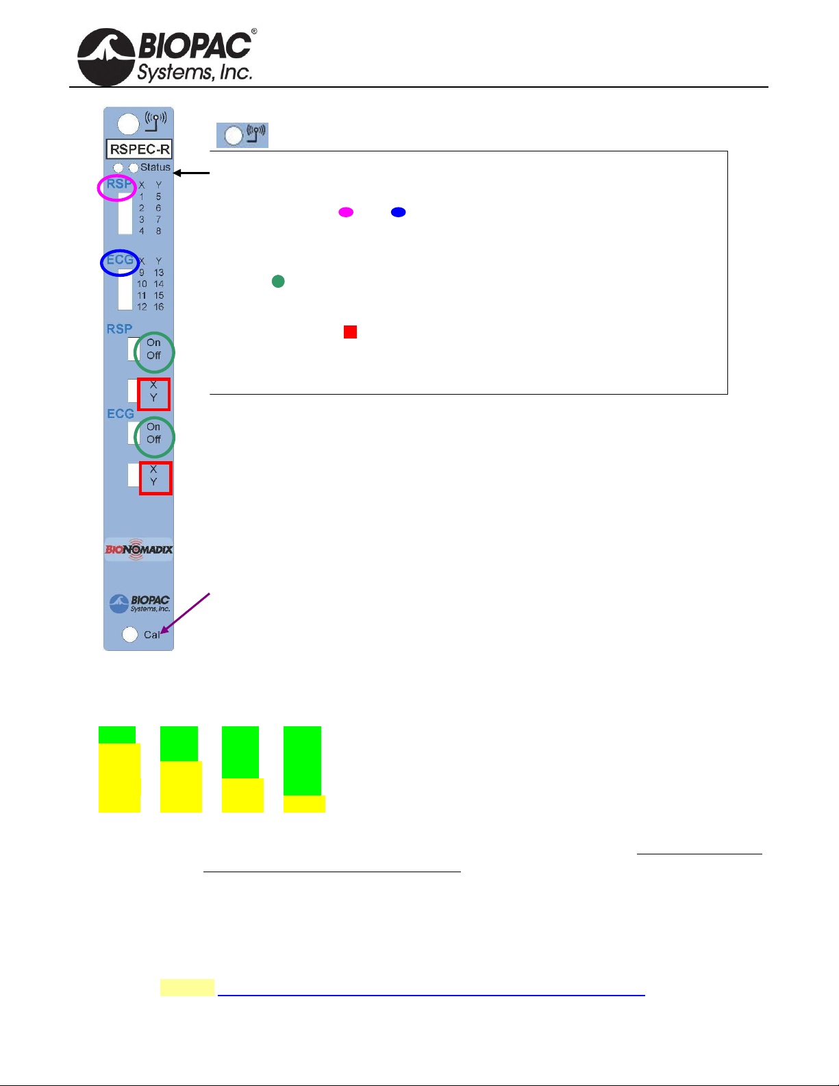
The RSPEC Receiver unit is depicted, but controls operate similarly for all units.
Wireless antenna input
Receiver LED: Steady green when paired with transmitter. Blinks amber once per
second when communication is interrupted.
Input Signals: A = B =
“A” Assigns the input signals for channels 1-8.
“B” Assigns the input signals for channels 9-16.
On/Off
Enables or disables module channels: “A”channels 1-8 “B” channels 9-16.
X/Y channel banks
Selects between “X” channel bank or “Y” channel bank.
“A” X bank is 1-4, Ybank is 5-8.
“B” X bank is 9-12, Ybank 13-16.
NOTE: “A” or “B” banks that are turned off will free up those associated Analog
channels for use by other signal types.
Cal: Recessed Calibration button. NOTE: Calibration is not required, most users
can use factory presets. Calibration is an advanced procedure.
TRANSMITTER BATTERY LIFE
Transmitter battery life is described below as a change of color in the sequence of LED flashes.
LED Color Pattern Charge %
green green green green 75% - 100%
yellow green green green 50% - 75%
yellow yellow green green 25% - 50%
yellow yellow yellow green 5% - 25%
yellow yellow yellow yellow < 5%
IMPORTANT: If the transmitter is to be stored for prolonged periods, it is strongly recommended that the
battery be fully charged and the transmitter turned off prior to storage. Failure to do so may
result in permanent damage to the battery.
SOFTWARE SETUP
Recording data with AcqKnowledge software
After completing setup, click Start in the AcqKnowledge software to begin recording data.
If the paired signal is interrupted due to electrical interference or a subject wandering out of range, the most
recently-acquired data point will be retained, with normal acquisition continuing once communication is
reestablished. See also: BioNomadix Operational Range and Transmission Characteristics.

PRODUCT SHEET
info@biopac.com
support@biopac.com
www.biopac.com
BIOPAC Hardware | BioNomadix Series | Page 7 - 26 Updated: 8.18.2020
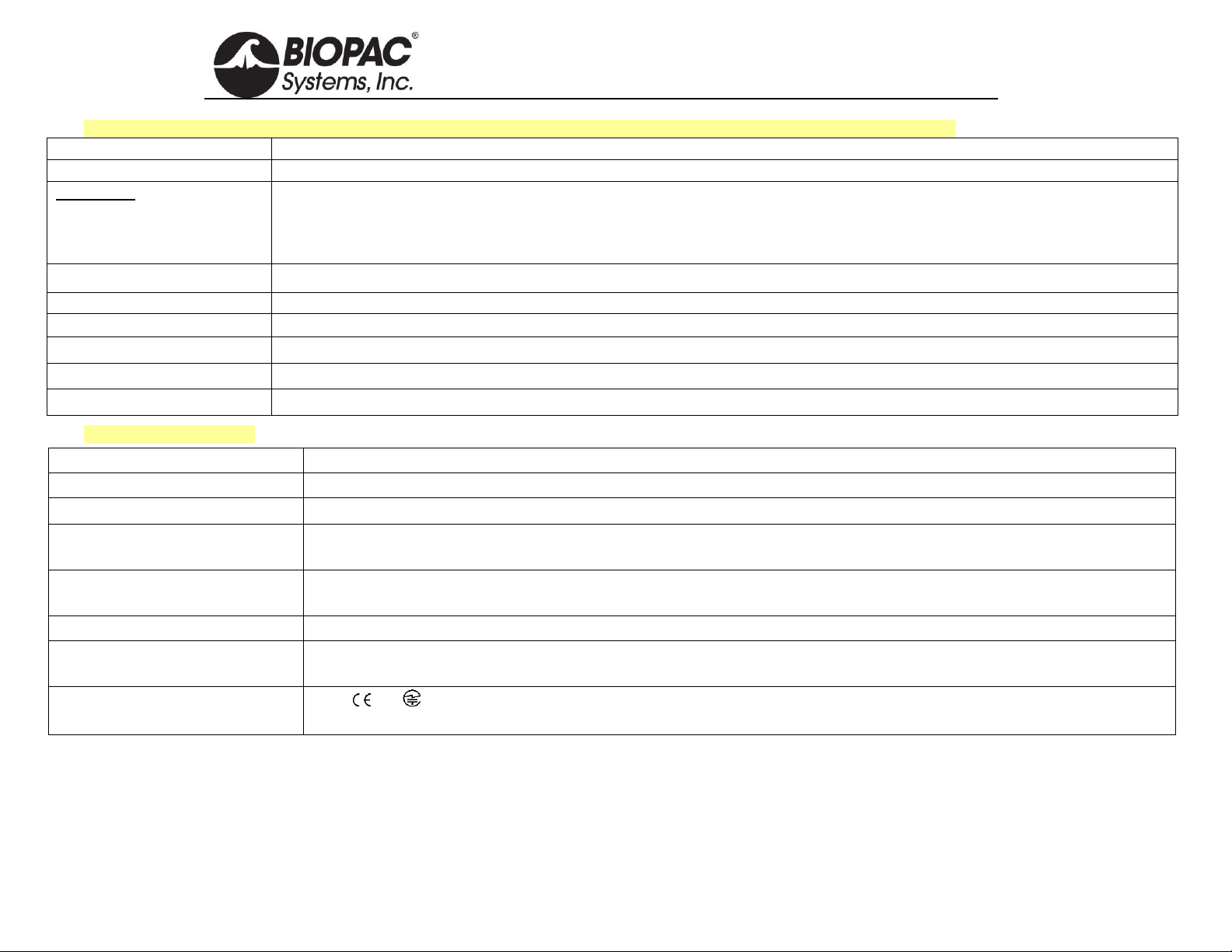
FULL BIONOMADIX MODULE SPECS
Table 1: BioNomadix Dual Biopotential Pairs –See Table 2 for Dual Transducer, Table 3 for Combo Pairs, and Table 4 for Accelerometer
BioNomadix Pair
BN-ECG2
BN-EEG2
BN-EGG2
BN-EMG2
BN-EOG2
Signal type:
Dual Channel ECG
Dual Channel EEG
Dual Channel EGG
Dual Channel EMG**
Dual Channel EOG
Bandlimits Max:
Factory preset:
Filter options:
Alternative signal:
0.05 Hz to 150 Hz
1 Hz to 35 Hz
0.05 or 1 Hz HP, 35
or 150 Hz LP
Heart Rate Mode
0.1 Hz to 100 Hz
0.5 Hz to 35 Hz
0.1 or 0.5 Hz HP, 35 or
100 Hz LP
Delta, Theta, Alpha, Beta
0.005 Hz to 1.0 Hz
0.005 Hz to 1.0 Hz
0.005 Hz HP, 1 Hz LP
5 Hz to 500 Hz
10 Hz to 500 Hz
5 or 10 Hz HP, 250 or
500 Hz LP
Envelope Detection Mode
0.005 Hz to 100 Hz
0.005 Hz to 35 Hz
0.005 or 1 Hz HP, 35
or 100 Hz LP
Derivative Mode
Notch filter:
50/60 Hz user-controlled switch; typically not required—factory preset OFF. See Appendix for more hardware-specific output
options.
Noise Voltage
(shorted inputs):
0.9 µV rms
(bandwidth of 0.05
Hz to 150 Hz)
0.2 µV rms (bandwidth of
0.10 Hz to 100 Hz)
0.5 µV rms (bandwidth of
0.005 Hz to 1 Hz)
1.5 µV rms (bandwidth of
1.0 Hz to 500 Hz)
0.9 µV rms
(bandwidth of 0.005
Hz to 100 Hz)
Input Voltage Range:
up to 10 mV P-P
up to 2 mV P-P
up to 10 mV P-P
up to 10 mV P-P
up to 10 mV P-P
Output Voltage Range:
±10 V (receiver output)
CMRR
110 dB typical at 50/60Hz; 90dB minimum for ECG, EEG, EMG, and EOG, 100 db minimum for EGG
CMII
1000 MΩ (50/60 Hz)
Differential Input
Impedance:
2 MΩ
Fixed Gain:
2,000
10,000
2,000
2,000
2,000
Operating Time:
72-90 hours
Included strap:
137 cm - BN-
STRAP137
76 cm - BN-STRAP76
137 cm - BN-STRAP137
33 cm - BN-STRAP33
76 cm –BN-
STRAP76
Size & Weight:
Transmitter (approx.): 6 cm x 4 cm x 2 cm; 54 grams; Receiver (approx).: 4 cm x 11 cm x 19 cm; 380 grams
Input:
See BioNomadix electrode lead cable options (BN-ELxx-LEADx). Each biopotential transmitter requires at least one GND. To
eliminate redundant biopotential GND, use a 3-lead electrode lead cable for one input (CH A or B) and a 2-lead electrode lead
cable for the other input (CH A or B) on each BioNomadix transmitter. Use BN-ADAPT-TP2/3 for Touchproof connections,
including BN-EEGCAP-SYS.
**NOTE for BN-EMG2: Due to digital data buffering and wireless transmission factors (large fixed component (15.6 ms) and small variable component
(±0.5 ms rms), the BN-EMG2 module is not recommended for applications such as Nerve Conduction Velocity or any physiological signal where
equivalently small timing differences are being measured. For these types of studies, BIOPAC recommends the wired EMG100C amplifier.

PRODUCT SHEET
info@biopac.com
support@biopac.com
www.biopac.com
BIOPAC Hardware | BioNomadix Series | Page 8 - 26 Updated: 8.18.2020
Table 2: BioNomadix Dual Transducer –See Table 1 for Biopotentials, Table 3 for Combo Pairs, and Table 4 for Accelerometers
BioNomadix
BN-SKT2
BN-RSP2
BN-GONIO
BN-STRIKE
Signal type:
Dual Channel SKT temp
Dual Channel RSP resp
Dual Channel Goniometry
Dual Channel Strike Data
BandlimitsMax:
Factory preset:
Filter Options:
DC to 10 Hz
DC to 1 Hz
DC, 0.5 Hz HP, 1 or 10 Hz LP
DC to 10 Hz
DC to 1 Hz
DC, 0.5 Hz HP, 1 or 10 Hz LP
DC to 100 Hz
DC to 10 Hz
DC, 3 Hz, 10 Hz, or 100 Hz
LP
DC to 100 Hz
DC to 10 Hz
DC, 3 Hz, 10 Hz, or 100 Hz LP
Notch filter:
50/60 Hz user-controlled switch; typically not required—factory preset OFF. See Appendix for
additional hardware-specific output options.
50/60 Hz user-controlled
switch –factory preset OFF
Resolution:
0.01° C (rms)
FSR/4096; (4.88 mV)
0.01rotation (rms)
N/A
Signal range:
13 to 51° C
± 10 V (at output)
± 180
± 10 V (at output)
Output Voltage range:
± 10 V (receiver output)
Operating time:
72-90 hours
Included strap:
137 cm - BN-STRAP-137
137 cm - BN-STRAP-137
76 cm - BN-STRAP-76 &
BN-STRAP-33
33 cm - BN-STRAP-33
Input:
BN-TEMP-A/B-XDCR
BN-RESP-XDCR
BN-GON-110-XDCR
BN-GON-150-XDCR
BN-GON-F-XDCR
BN-TOR-100-XDCR
BN-TOR-150-XDCR
BN-STRIKE-XDCR
BN-ADAPT-GONIO
This adapter connects goniometers and torsiometers to a wireless BN-GONIO Transmitter, use one adapter per channel.
BioNomadix goniometers and torsiometers include the required BN-ADAPT-GONIO adapter(s):
•Two adapters included with BN-GON-110-XDCR and BN-GON-150-XDCR goniometers
•One adapter included with BN-GON-F-XDCR finger goniometer and BN-TOR-110-XDCR and BN-TOR-150-XDCR torsiometer
Adapters can also be used with existing BIOPAC or 3rd-party goniometers and torsiometers to make them compatible with the BioNomadix wireless
transmitter. These adapters are required if not using BioNomadix Transducers.

PRODUCT SHEET
info@biopac.com
support@biopac.com
www.biopac.com
BIOPAC Hardware | BioNomadix Series | Page 9 - 26 Updated: 8.18.2020
Table 3: BioNomadix Combo Pairs –See Table 1 for Biopotentials, Table 2 for Dual Transducer and Table 4 for Accelerometer
BioNomadix
BN-RSPEC
BN-PPGED
BN-NICO
BN-DYNEMG
Signal type:
RSP plus ECG
PPG plus EDA
Z and dZ/dt
Dynamometry plus EMG
Excitation:
--
--
Type: Alternating current
sine wave
Current: 1 mA rms
Frequency: 50 kHz
--
BandlimitsMax:
Factory preset:
Filter Options:
Respiration (CH A):
see BN-RSP2 spec
ECG (CH B) :
see BN-ECG2 spec
Both: DC to 10 Hz:
PPG: 0.5 Hz to 3 Hz
EDA: DC to 3 Hz
Both: DC, 0.5 Hz HP, 3 or 10 Hz LP
EDA: 1 Hz LP
Both: DC to 50 Hz*
Both: DC to 50 Hz*
DC, 1, 3, 5, 50 Hz*LP
*Units shipped before
11/2016 are bandlimited
to 10 Hz.
Dyn: DC 100 Hz
Dyn: DC to 10 Hz
Dyn: DC, 3 Hz, 10 Hz, or
100 Hz LP
EMG: see BN-EMG2
specs
Notch filter:
50/60 Hz user-controlled switch; typically not required—factory preset OFF. See Appendix for additional hardware-specific
output options.
Resolution:
see BN-RSP2 and BN-ECG2
specs
PPG: FSR/4096; (4.88 mV)
EDA: 0.012 µS (min step)
Z: nominally ~0.05 Ω
(rms) at 10 Hz BW
dZ/dt: ~0.0075 Ω/sec
(rms) at 10 Hz BW
Dyn: 35 micro kg-f/cm2
(0.0005 psi) (rms)
EMG: see BN-EMG specs
Signal range:
see BN-RSP2 and BN-ECG2
specs
PPG: ±10 V (at output)
EDA: 0 to 50 µS; excitation: 0.5 V
constant V
Z: 5 to 100 Ω (mag)
dZ/dt: ±10 Ω/sec
Dyn: 0 –1.055 kg-f/cm2
EMG: up to 10 mV P-P
Output Voltage range:
± 10 V (receiver output)
Operating time:
72-90 hours
24 hours
24 hours
75 hours
Included strap:
137 cm - BN-STRAP137
33 cm - BN-STRAP33
137 cm - BN-STRAP137
33 cm - BN-STRAP-33
Input:
CH A: BN-RESP-XDCR
CH B: BN-ELxx-LEAD3
CH A: BN-PULSE-XDCR or BN-
PULSEEAR-XDR
CH B: BN-EDA-LEAD2 or BN-EDA25-
LEAD2
2 x BN-EL50-LEAD4
(or 2 x BN-EL50-LEAD2)
CH A: BN-CLENCH-XDCR
CH B: BN-ELxx-LEAD3
PRODUCT SHEET
info@biopac.com
support@biopac.com
www.biopac.com
BIOPAC Hardware | BioNomadix Series | Page 10 - 26 Updated: 8.18.2020
Table 4: BioNomadix Accelerometer–See Table 1 for Biopotentials, Table 2 for Dual Transducer, and Table 3 for Combo Pairs
Table 5: Common Specs
Operational Range:
10 meters (line-of-sight) typical in standard laboratory setups. See also: Operational Range and Characteristics.
Delay:
Large fixed component (15.6 ms) and small variable component (±0.5 ms rms)
Operating Temp & Humidity:
Temperature: 5-45C Humidity: 95% non-condensing
Size & Weight:
Transmitter: (approx.): 6 cm x 4 cm x 2 cm: 54 grams
Receiver: (approx.): 4 cm x 11 cm x 19 cm: 380 grams
Transmitter:
Type: Ultra-low power, 2.4 GHz bi-directional digital RF transmitter
Rate: 2,000 Hz (between transmitter and receiver)
Receiver Power:
Use with an MP Research System or with isolated power supply IPS100C for 3rd-party data acquisition system.
Battery & Charger:
BioNomadix transmitters use an L-ion battery: full charge takes approx. 1 hour to provide maximum operating time.
A battery charger is included with each module pair. See BN-CHRG for charge time and recharge cycle details.
Compliance:
FCC, , IC, - FCC Part 15 B - FCC ID: receiver: ZWIBNXR1, transmitter ZWIBNXT1
IC: receiver: 9901A-BNXR1, transmitter: 9901A-BNXT1
BioNomadix
BN-ACCL3
Signal type:
G (X, Y, Z)
Bandlimits Max:
Factory preset:
Filter Options:
Alternative signal:
±2, ±4, ±8 or ±16 G
± 16 G at 400 Hz LP
DC to 3.13 Hz LP up to 400 Hz LP (in power of 2 steps)
Tap Event Mark Mode (replaces G)
Resolution:
X: 5 mg rms, Y: 6 mg rms, Z: 9 mg (rms) (±2 G scale at 400 Hz LP)
Signal range:
Selectable: ±2, ±4, ±8 or ±16 G
Output Voltage range:
±10 V (receiver output)
Operating time:
72-90 hours
Included strap:
33 cm - BN-STRAP33
Input:
Attach BioNomadix transmitter to subject –no additional hardware input required; sensor is internal to transmitter.
PRODUCT SHEET
info@biopac.com
support@biopac.com
www.biopac.com
BIOPAC Hardware | BioNomadix Series | Page 11 - 26 Updated: 8.18.2020
BIONOMADIX ELECTRODE LEADS
All BioNomadix electrode leads use lightweight, insulated tinsel wire 1.25 mm OD with female mini-pinch clips
and squeeze lock connectors
2-LEAD BIONOMADIX ELECTRODES LEADS (also for biopotential Smart Amplifiers)
Lead wires: 2 (red and white)
Electrode clips: 2
Length: BN-EL15-LEAD2: 15 cm, BN-EL30-LEAD2; 30 cm, BN-EL45-LEAD2; 45 cm
Interface: Secondary channel lead for the following BioNomadix Transmitters: BN-ECG2, BN-
EEG2, BN-EGG2, BN-EMG2, BN-EOG2, (first channel lead should be a BN-ELxx-
LEAD3 three lead set to establish ground). Do not use for EDA or NICO!
2-LEAD FOR NICO –BN-EL50-LEAD2
Lead wires: 2 (insulated leads black)
Electrode clips: 2 (alligator clips with teeth)
Length: 50 cm
Interface: NICO CH A or CH B
To eliminate redundant ground leads for biopotentials, use 3-lead for primary
input and 2-lead for secondary input for each BioNomadix unit.
3-LEAD BIONOMADIX ELECTRODES LEADS (also for biopotential Smart Amplifiers)
Lead wires: 3 (red, white, and black)
Electrode clips: 3
Length: BN-EL15-LEAD3; 15 cm, BN-EL30-LEAD3; 30 cm, BN-EL45-LEAD3; 45 cm
Interface: Primary and secondary channel lead for the following BioNomadix Transmitters: BN-ECG2,
BN-EEG2, BN-EGG2, BN-EMG2, BN-EOG2. Do not use for EDA or NICO!
4-LEAD BIONOMADIX ELECTRODE LEADS
Leads: 4 (red x 2 and white x 2)
Electrode clips: 4
Length: BN-EL50-LEAD4; 50 cm
Interface: designed for BN-NICO: CH A or CH B (can be used
with other BioNomadix biopotential transmitters)
Connection: See diagram (right) for BN-EL50-LEAD4 leads and
EL500 paired spot electrodes.
EDA BIONOMADIX ELECTRODE LEADS
(also for Smart Amplifier EDA100D)
Leads: 2 (red and black)
Electrode clips: 2
Length: BN-EDA-LEAD2; 15 cm, BN-EDA25-LEAD2; 25 cm
Interface: Only use in CH B EDA on wireless BioNomadix
Transmitter BN-PPGED
BIONOMADIX TO TOUCHPROOF ADAPTERS
Leads: 2 (red and white, BN-ADAPT-2) or 3 (red, white and black, BN-ADAPT-3)
Electrode clips: 2 (BN-ADAPT-2) or 3 (BN-ADAPT-3)
Length: 10 cm
Interface: Use these adapters to connect 1.5 mm Touchproof electrodes to a BioNomadix transmitter.

PRODUCT SHEET
info@biopac.com
support@biopac.com
www.biopac.com
BIOPAC Hardware | BioNomadix Series | Page 12 - 26 Updated: 8.18.2020
BIONOMADIX OPERATIONAL RANGE AND TRANSMISSION CHARACTERISTICS
The BioNomadix system is a very low power transmission system designed for physiological measurements in a
laboratory setting. In this explanation, a BioNomadix transmitter is referred to as series BN-Tx and a BioNomadix
receiver as series BN-Rx.
Primary design objectives for the BioNomadix system:
1) BN-Tx and BN-Rx units to emulate operation, as if
“attached by cable”
2) Transmission effects not to disturb physiological source
3) Classification subject to class B digital device pursuant to
FCC part 15
4) Long BN-Tx operational time, after recharge
5) Quick recharge time, under one hour
6) Bn-Tx units to be as lightweight, rugged
and small as possible
7) Minimal user setup required, simply
power up and start collecting data
BioNomadix Operational Range and Characteristics
A primary objective of the BioNomadix System is that it cannot behave in a fashion that would permit any arbitrary
time delay between transmitter and receiver. This objective is critical for the BioNomadix System because it insures
robust time synchronization between any BN-Tx units and external hardware. Because of the requirement to “behave
as though a cable connects BN-Tx and BN-Rx”, the BioNomadix System required a special and optimized protocol to
insure the best possible attempts to send data, within a limited (10 sample) time frame. If data could not be sent within
this time frame, then data would be replaced with the last data value sent for a short time period (for up to about one
second) thereafter until finally, assuming a reconnect was not possible, the transmitted data (not received) will be
identified as null (zero) values.
The BioNomadix System operational transmission range is 10 meters line-of-sight, typical, in standard laboratory
environments. Operational range can vary depending on factors such as presence of electromagnetic interference,
multi-path, or radio frequency signal blocking. In the event of a communications failure, BioNomadix Tx and Rx
modules will attempt to re-establish communications until such communications can be re-established.
BioNomadix Tx are purposely kept at very low power so as not to disrupt the sensitive biophysical parameter
measured, to enhance battery life, and to satisfy the relevant FCC regulations. If a BN-Tx and BN-Rx pair is used
outside of the laboratory (without the benefit of multi-path) and if the BN-Tx is line-of-sight blocked from the BN-
Rx, then communication dropouts are increasingly likely. A functional solution is to keep the BN-Tx and BN-Rx in
constant line-of-site view.
BioNomadix signal performance is best with “line-of-sight” connection from transmitter unit to receiver unit. Signal
dropouts happen when a conductive surface (metal or human body) is placed between the transmitter and receiver
unit. If this happens, and there are no other radio frequency reflective surfaces in the room, then the radio waves can’t
get from transmitter unit to receiver. This phenomenon is referred to as “body-blocking.” The solution is to place the
transmitter and receiver units closer together and to eliminate potential for body-blocking.
Case studies
Case 1: Multiple people wearing BioNomadix Tx units are walking around in a room and the BN-Rx units are placed
in a nearby room. Periodically, when body blocking occurs, short signal dropouts are noted.
Solution 1:Place the BN-Rx units, with MP160/150, directly above the subjects in the room. This will greatly
minimize the potential for body-blocking, from Tx unit to Rx unit, as subjects move around.
Case 2: Multiple people wearing BioNomadix Tx units are sitting in a room with a central table. The BioNomadix Rx
units are placed in a nearby room. Periodically, when body blocking occurs, short signal dropouts are noted.
Solution 2: Mount the receiver (BN-Rx) units, with MP160/150, underneath the center of the table, around
which the subjects are sitting. Mount a platform to the underside of the table and rest the receiver with
MP160/150 on it. This situation places the receivers just one or two meters away from the transmitters
attached to the subjects.

PRODUCT SHEET
info@biopac.com
support@biopac.com
www.biopac.com
BIOPAC Hardware | BioNomadix Series | Page 13 - 26 Updated: 8.18.2020
BioNomadix Transducers
Pulse BioNomadix Transducer BN-PULSE-XDCR
Emitter/Detector Wavelength: 860 nm ± 60 nm
Optical LP Filter Cutoff: 800 nm
The operational range of the emitter and detector falls within the wavelength
range of 800 nm to 920 nm. The filter is placed over the receiver; the filter of
800 nm is an optical lowpass, so wavelengths longer than 800 nm will pass
thru.
Nominal Output: 20 mV (peak-peak)
Power: 10 mA drive current
Sterilizable: Yes (contact BIOPAC for details)
Dimensions (L x W x H): 16 mm x 17 mm x 8 mm
Transducer Weight: 4.5 grams Cable: 45 cm
Interface: Use in CH A PPG on the BioNomadix BN-PPGED or with Smart Amplifier
PPG100D
Pulse Earclip Transducer BN-PULSEEAR-XDR
Emitter/Detector Wavelength: 890 nm (nominal maximum)
Optical Low Pass Filter Cutoff ambient visible light filter
The transducer operates with the BioNomadix Pulse Transmitter (BN-
PPGED) and consists of a matched infrared emitter and photo-diode, which
transmits changes in infrared reflectance resulting from varying blood flow.
Wavelength: 800-1,000 nm (70% spectral response)
Nominal Output: 20 mV (peak-peak)
Power: 10 mA drive current
Sterilizable: Yes (contact BIOPAC for details)
Dimensions (L x W x H): 16 mm x 17 mm x 8 mm
Transducer Weight: 4.5 grams Cable length: 80 cm
Interface: Use in CH A PPG on the BioNomadix BN-PPGED or with Smart Amplifier
PPG100D
Respiration Transducer BN-RESP-XDCR
Response: True DC
Circumference Range: 15 cm x 150 cm (increase with a longer strap)
Dimensions: 66 mm (long) x 40 mm (wide) x 15mm (thick)
Weight: 18 grams
Sterilizable: YES: use standard gas sterilization techniques [i.e., Ethylene Oxide (EtO)]
Variable Resistance Output: 5 - 125 KOhm
Cable: 30 cm
Interface: BN-RSP2 CH A RSP or CHB RSP, BN-RSPEC CHA RSP, or Smart
Amplifier RSP100D

PRODUCT SHEET
info@biopac.com
support@biopac.com
www.biopac.com
BIOPAC Hardware | BioNomadix Series | Page 14 - 26 Updated: 8.18.2020
Clench Force Transducer BN-CLENCH-XDCR
Pressure Range: 0 to 1.0546 Kg-f/cm^2 (0 to 15 psi)
Error Band: ± 2% full scale
Accuracy: ±25% full scale –best fit straight line
Output: 25 mV/0.01 Kgf/cm^2 (0.176 V/psi)
Bulb Diameter: 5.8 cm
Bulb Length: 11.1 cm
Weight: 108 grams
Cable Length: 45 cm
Interface: Use with the BN-DYNEMG Dynamometer and EMG module
Heel-Toe Strike Transducer BN-STRIKE-XDCR
Nominal Output Range: -1 to +1 Volt
Nominal Contact Force: 200 g to indicate heel-toe strike
Attachment: TAPE 1, TAPE 2, vinyl electrical or duct tape
FSR Dimensions: 18.3 mm (dia) x 0.36 mm (thick) and 30 cm pigtail lead
FSR Active Area: 12.7 mm diameter
Interface: BN-STRIKE transmitter (STRK A, STRK B)
Skin Temperature Transducer BN-TEMP-A-XDCR
Nominal Resistance: 2252 ohm at 25° C
Maximum operating temperature: 60° C
Accuracy and Interchangeability: 0.2° C
Response Time: 1.1 sec (attached to skin)
Compatibility: YSI series 400 temperature probes
Sterilizable: NO (Not designed for immersion)
Cable: 30 cm
Dimensions: 9.8 mm (diameter) x 3.3 mm (high)
Interface: BN-SKT2 only: CH A SKT and/or CH B SKT, or Smart Amplifier SKT100D
Skin Temperature Transducer BN-TEMP-B-XDCR (Fast Response)
Nominal resistance: 2252 ohm @ 25° C
Maximum operating temperature: 60° C (when used with BN-SKT2)
Accuracy and Interchangeability: 0.2° C
Response Time: 0.6 sec (in air)
Compatibility: YSI series 400 temperature probes
Sterilizable: NO (Not designed for immersion)
Cable: 30 cm
Dimensions: 1.7 mm (diameter) x 5 mm (long)
Interface: BN-SKT2 only: CH A SKT and/or CH B SKT, or Smart Amplifier SKT100D


PRODUCT SHEET
info@biopac.com
support@biopac.com
www.biopac.com
BIOPAC Hardware | BioNomadix Series | Page 16 - 26 Updated: 8.18.2020
BIONOMADIX ACCESSORIES SPECS
BioNomadix Shirt
Attachment Features: 22 pockets: 2 neck front, 2 neck back, 4 chest center, 4 back center, 2 hip front, 2
hip back, 3 left arm, 3 right arm
4 zippers: right front from arm to hip, left back from shoulder to hip, right and left
under arm from neck front to neck back
4 strap bands: 4 rows of strap bands (2 loops front, 2 loops back) for RSP
transducer strap
Materials: Black 6 oz. eyelet mesh 88% Polyester / 12% Spandex; metal zippers
Sizes: BN-SHIRT-XS extra small BN-SHIRT-L large
BN-SHIRT-S small BN-SHIRT-XL extra large
BN-SHIRT-M medium
Care instructions: Machine Wash, Warm / Line Dry
BioNomadix Strap
Dimensions: Length 20 cm, 33 cm, 76, cm, 137 cm (all widths 2.5 cm)
Material: stretch Velcro®- hook/loop type
Use with: BioNomadix Transmitters
Length: BN-STRAP-20; 20 cm BN-STRAP-33; 33 cm
BN-STRAP-76; 76 cm BN-STRAP-137; 137 cm
BioNomadix 10/20 EEG Cap System
Attachment: Ribbon cable (25 cm) from cap to 19 Touchproof (1.5 mm) sockets
Material: Lycra
Use with: BN-EEG2
Lead adapters: BN-ADAPT-TP2 or BN-ADAPT-TP3 depending on sites to be recorded
Sizes: BN-CAP-SMALL (50-54 cm,) BN-CAP-MEDIUM (54-58 cm,)
BN-CAP-LARGE (58-62 cm)
Components: 1 x medium cap with 19-pin ribbon cable
1 x mating cable with 1.5 mm Touchproof connectors
2 x earclip reference electrodes
1 x blunt-tipped syringe
1 x EEG recording gel
1 x chest harness (holds cap in place)
1 x liquid soap (to wash cap after use)
WHITE TIP
WIRE COLOR
RED TIP
Fp1
Brown
Fp2
F3
Red
F4
C3
Orange
C4
P3
Yellow
P4
01
Green
02
F7
Blue
F8
T3
Violet
T4
T5
Gray
T6
Gnd
White
Cz
Fz
Black
Pz

PRODUCT SHEET
info@biopac.com
support@biopac.com
www.biopac.com
BIOPAC Hardware | BioNomadix Series | Page 17 - 26 Updated: 8.18.2020
BioNomadix Battery Charger: BN-BAT-CHRG
To charge, the BioNomadix Transmitter must be in the OFF position and
have no electrode leads or transducers attached.
Connector: DC polarized squeeze-clip plug to mate with all BioNomadix Transmitters
Number of cells: 1 L-ion
Charger current 1000 mA (660 mA for IB-16800
Current tolerance: +10%
Voltage limit: Preset
Voltage limit tolerance: +0.2%
Operating temperature: 0°C to 40°C
Input voltage: 90 VAC to 240 VAC
Frequency 50 Hz to 60 Hz
Wall plug: ships with US blades; adapters available for Euro, China or Australia
Output cable length: 1.7 meter (~6 feet)
Connector DC polarized squeeze-clip plug to mate with all BioNomadix Transmitters
Weight: 142 grams (5 oz.)
Dimensions: 75 mm x 51 mm x 40 mm
Lithium Ion Chemistry
Termination algorithm: CCCV
Termination indicated Current falls to limit value/5
Top-off charge: 1 hour or current falls to limit value/10
Restart threshold: 7/8 of termination voltage or every 2 hours
Maintenance charge: N/A
Charge voltage limit: Preset to 4.20 V (one L-ion cell)
Override timer: None
IMPORTANT: If the transmitter is to be stored for prolonged periods, it is strongly recommended that the
battery be fully charged and the transmitter turned off prior to storage. Failure to do so may
result in permanent damage to the battery. To avoid shortening battery life, it is also
recommended that transmitter be disconnected from the charger prior to storing for long
periods. For extremely long-term disuse, transmitter should be charged once a month, then
disconnected between charge cycles.

PRODUCT SHEET
info@biopac.com
support@biopac.com
www.biopac.com
BIOPAC Hardware | BioNomadix Series | Page 18 - 26 Updated: 8.18.2020
BIONOMADIX COMPLIANCE STATEMENT
This device complies with part 15 of the FCC Rules. Operation is subject to the following two conditions: (1) This
device may not cause harmful interference, and (2) this device must accept any interference received, including
interference that may cause undesired operation.
INDUSTRY CANADA INFORMATION
Under Industry Canada regulations, this radio transmitter may only operate using an antenna of a type and
maximum (or lesser) gain approved for the transmitter by Industry Canada. To reduce potential radio
interference to other users, the antenna type and its gain should be so chosen that the equivalent isotropically
radiated power (e.i.r.p.) is not more than that necessary for successful communication.
This radio transmitter (IC: 9901A-BNXR1) has been approved by Industry Canada to operate with the antenna
types listed below with the maximum permissible gain and required antenna impedance for each antenna type
indicated. Antenna types not included in this list, having a gain greater than the maximum gain indicated for that
type, are strictly prohibited for use with this device.
WLAN antenna, maximum gain 1.5 dBi, 50 ohm
This device complies with Industry Canada licence-exempt RSS standard(s). Operation is subject
to the following two conditions: (1) this device may not cause interference, and (2) this device
must accept any interference, including interference that may cause undesired operation of the device.
Conformément à la réglementation d'Industrie Canada, le présent émetteur radio peut
fonctionner avec une antenne d'un type et d'un gain maximal (ou inférieur) approuvé pour
l'émetteur par Industrie Canada. Dans le but de réduire les risques de brouillage radioélectrique
à l'intention des autres utilisateurs, il faut choisir le type d'antenne et son gain de sorte que la
puissance isotrope rayonnée équivalente (p.i.r.e.) ne dépasse pas l'intensité nécessaire à
l'établissement d'une communication satisfaisante.
Le présent émetteur radio (IC: 9901A-BNXR1) de modèle s'il fait partie du matériel de catégorieI) a été approuvé
par Industrie Canada pour fonctionner avec les types d'antenne énumérés ci-dessous et ayant un gain admissible
maximal et l'impédance requise pour chaque type d'antenne. Les types d'antenne non inclus dans cette liste, ou
dont le gain est supérieur au gain maximal indiqué, sont strictement interdits pour l'exploitation de l'émetteur.
réseau local sans fil antenne, le gain max 1.5 dBi, 50 ohm
Le présent appareil est conforme aux CNR d'Industrie Canada applicables aux appareils radio
exempts de licence. L'exploitation est autorisée aux deux conditions suivantes : (1) l'appareil ne
doit pas produire de brouillage, et (2) l'utilisateur de l'appareil doit accepter tout brouillage
radioélectrique subi, même si le brouillage est susceptible d'en compromettre le fonctionnement.
CLASS A ITE
この装置は、クラスA情報技術装置です。この装置を家庭環境で使用すると
電波妨害を引き起こすことがあります。この場合には使用者が適切な対策を
講ずるよう要求されることがあります。VCCI-A

PRODUCT SHEET
info@biopac.com
support@biopac.com
www.biopac.com
BIOPAC Hardware | BioNomadix Series | Page 19 - 26 Updated: 8.18.2020
BIONOMADIX—OPTIONAL CALIBRATION
Isolated Power Supply
To use BioNomadix with the Isolated Power Supply (IPS100C), use CBL102 cable to connect the IPS100C to
the Receiver output channel. This is accessible via the front panel of the IPS100C.
Signal Validation
BioNomadix units are factory calibrated, but if user-calibration is desired for measurement verification, the
following steps may be used. Please see the appropriate section for BioNomadix calibration guidelines.
•BN-ECG, BN-EEG, BN-EGG, BN-
EMG, BN-EOG
•BN-EDA
•BN-NICO
•BN-PPG and BN-RSP
•BN-SKT
•BN-GON and BN-TOR
•BN-STRIKE
•BN-DYNEMG
•BN-ACCL
BN-ECG, BN-EEG, BN-EGG, BN-EMG, BN-EOG BIOPOTENTIAL CALIBRATION
Three alligator clips will be required to calibrate a Biopotential
Transmitter/Receiver set.
1) Attach alligator clip to LEAD side of electrode pinch clip
(see figure on right).
2) Connect black and white pinch clips together (this
combination is attached to signal generator ground).
3) Connect red pinch clip to signal generator output for the Transmitter/Receiver set.
•ECG, EGG, EMG, EOG
The signal generator should be set to 1 mV peak to peak sine wave in the appropriate signal
frequency range for the Transmitter/Receiver set. The total gain of the Transmitter/Receiver
set is 2,000. The measured output voltage from the Receiver should be 1 mV p-p * 2000 or 2
V p-p. The maximum input signal is 10 mV p-p.
•EEG
The signal generator should be set to 1 mV peak to peak in the appropriate signal frequency
range for the Transmitter/Receiver set. The total gain of the Transmitter/Receiver set is
10,000. The measured output voltage from the Receiver should be 1 mV p-p * 10,000 or 10 V
p-p. The maximum input signal is 2 mV p-p.
PRODUCT SHEET
info@biopac.com
support@biopac.com
www.biopac.com
BIOPAC Hardware | BioNomadix Series | Page 20 - 26 Updated: 8.18.2020
BN-EDA ELECTRODERMAL CALIBRATION
Transmitter/Receiver set can be calibrated by applying a known resistance (conductance) to the EDA
electrode pinch connectors via alligator clips. Suggested values of conductance would be 0 µSiemens (infinite
ohms –no connection) and 10 µSiemens (100 K ohms). The EDA Transmitter/Receiver set outputs +10 V for
a 50 µS measured conductance. The EDA Transmitter/Receiver set will output approximately +2 V for a 10
µS measured conductance.
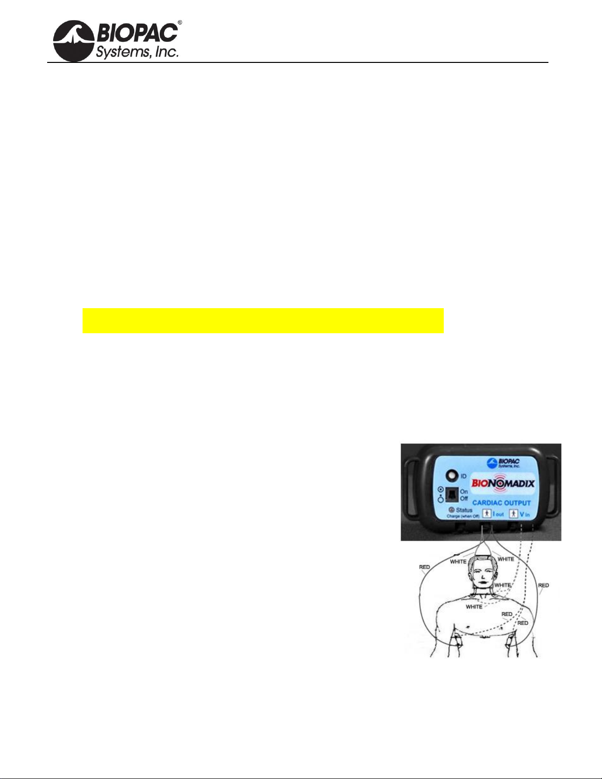
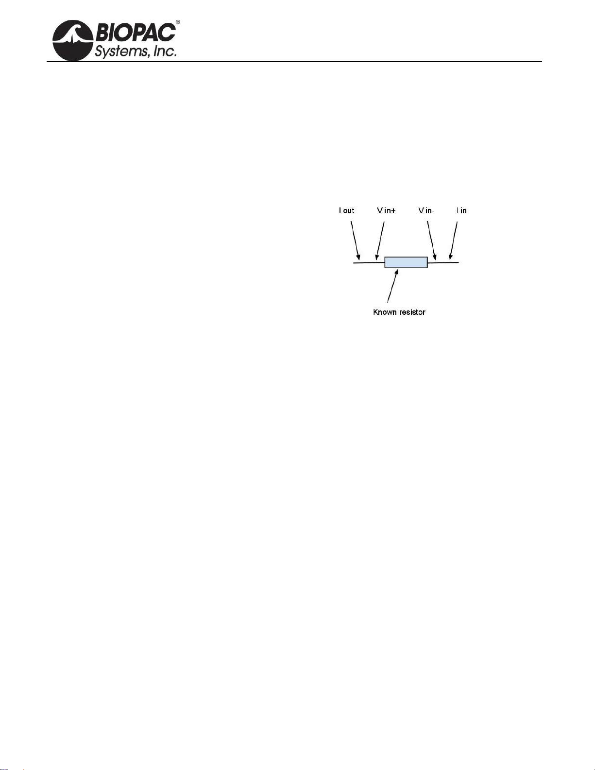
BN-NICO CALIBRATION
Mapping for Z: 0.8 V to 10 ohms 9 V to 100 ohms
The calibration values for Z are approximate. For a more
exact calibration for Z, introduce a 10 ohm resistor
between the paired leads (Iout, Vin+) and (Vin-, Iin) to
simulate a 10 ohm impedance magnitude. Use a 100 ohm
resistor to simulate a 100 ohm impedance magnitude. See
figure at right for details:
For the most accurate calibrations, use known impedances
(resistances) that bracket the expected high and low values
being recorded. For conventional noninvasive cardiac
output measurements, optimal low impedance is 15 ohms
and optimal high impedance is 40 ohms.
Mapping for dZ/dt:0 V to 0 ohms/sec 10 V to 10 ohms/sec
The calibration values for dZ/dt can be accomplished by introducing a known and varying resistance that can
be precisely set to a specific rate of change. For calibration related to cardiac output measurements, a varying
resistance of ±1 ohms/seconds to ±5 ohms/second is ideal. A photonically-isolated voltage controlled
resistance can be used for this calibration. A cadmium sulfide cell in parallel with a resistance of 25 ohms can
be employed in conjunction with a signal generator driven LED to provide a varying light intensity to
modulate the resistance of the cadmium sulfide cell.
BN-PPG AND BN-RSP PULSE AND RESPIRATION CALIBRATION
User-calibration not recommended, as the measurements performed are essentially dimensionless.
However, it’s possible to calibrate the PPG Transmitter/Receiver set by introducing a variable gray-scale
density pattern to the PPG probe in a dark environment. The RSP Transmitter/Receiver set can be calibrated
by applying differing amounts of force to the RSP transducer/belt combination to stretch the belt over
different distances.
BN-SKT SKIN TEMPERATURE CALIBRATION
Insert probe into temperature well set to the appropriate temperature. As an alternative, replace the thermistor
with known temperature(s) that reflects the specific temperature(s) simulated. The temperature probe
specifications are equivalent to YSI@ 400 series probes. The temperature range for the SKT
Transmitter/Receiver set is 13 to 51 degrees C. Using the specified temperature probe: 13 degrees provides a -
10 V output and 51 degrees provides a +10 V output.
Table of contents
Other BIOPAC Systems Measuring Instrument manuals


Popular Measuring Instrument manuals by other brands

Ronde & Schwarz
Ronde & Schwarz R&S FPL1007-P6 user manual

Fluke
Fluke ESA615 user manual

SMA Solar Technology
SMA Solar Technology SUNNY VIEW Quick reference guide for commissioning

IFM
IFM SI0558 operating instructions

X-Rite
X-Rite 962 Operator's manual

Emerson
Emerson Micro Motion 1700 Configuration and Use Manual


