BIOS Defender 530 Series User manual
Driving a Higher Standard
in Flow MeasurementSM
Defender™530
User Manual

2
Defender 530 User Manual
Table of Contents
Introduction .................................................................................................................... 1.0
Operation ........................................................................................................................ 2.0
Battery ............................................................................................................................2.1
Activation ........................................................................................................................2.2
Connections ....................................................................................................................2.3
Display Screen ................................................................................................................2.4
Menu Navigation ............................................................................................................2.5
Set Up .............................................................................................................................2.6
Measurements ...............................................................................................................2.7
Single ..............................................................................................................................2.8
Burst ...............................................................................................................................2.9
Continuous .....................................................................................................................2.10
Data Port ......................................................................................................................... 3.0
Optimizer Collect Light Software ...................................................................................3.1
Defender Firmware Upgrades .......................................................................................3.2
Annual Maintenance and Calibration ..............................................................................4.0
Shipping .......................................................................................................................... 5.0
Storage ........................................................................................................................... 6.0
Defender 530 Specifications ........................................................................................... 7.0
Factory Default Settings ................................................................................................. 8.0
Limited Warranty ............................................................................................................ 9.0
Troubleshooting Guide .................................................................................................... 10.0

Introduction
Operation
Data Port
Annual Maintenance and Calibration
Shipping
Storage
Defender 530 Specifications
Factory Default Settings
Limited Warranty
Troubleshooting Guide
2.0
6.0
3.0
7.0
4.0
8.0
5.0
9.0
10.0
1.0
2
1.0 Introduction
1.0
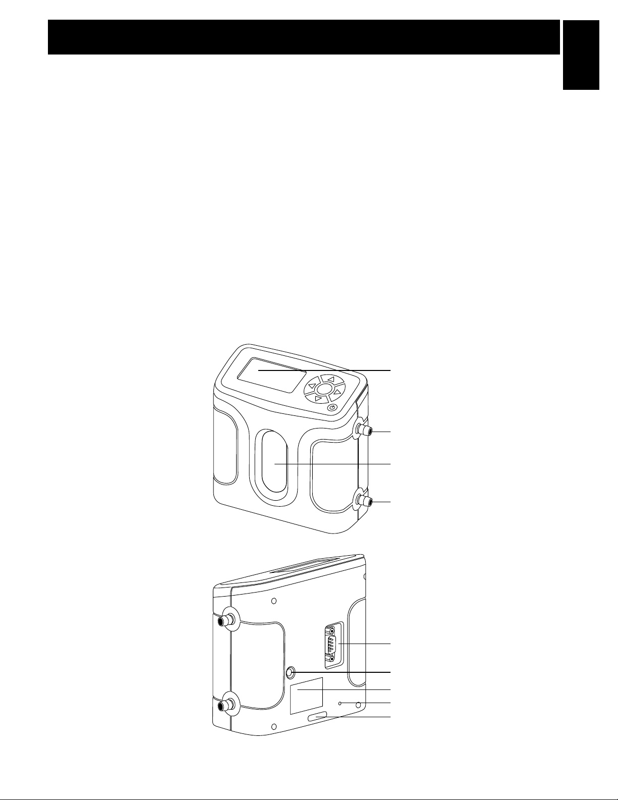
Data Port
Suction Fitting
Measuring Cell
Pressure Fitting
Charging Jack
Calibration Label
Reset Button
Display
Anti-tamper Label
The Defender 530 measures both volumetric and standardized gas flow with a volumetric flow accuracy of 1%
and standardized flow accuracy of 1.2% of reading. It uses our proven DryCal technology to measure volumetric
gas flow and is produced in our accredited laboratory in Butler, NJ.
This manual will provide information needed to operate your Defender. If at any time you have questions regarding
its operation, please contact Bios through our Web site (www.biosint.com) or call 973.492.8400 to speak with
a member of our professional customer service staff.
Your Defender comes with the following:
• ACPowerAdapter/Charger
• BiosOptimizerCollectLightSoftwareCD
• PCSerialCable
• LeakTestCaps(2);SaveforuseduringtheLeakTest
• CalibrationCerticate
• Manual
Carrying cases and accessories are available for purchase from Bios or your Bios distributor.

3
2.1 Battery
Your Defender battery is charged at the factory, but we recommend that you make sure it is fully charged
before initial use.
• ConnecttheACpoweradaptertotheDefender’sChargingJack(DCIn)
• PlugtheACpoweradapterintoanACoutlet
Initial charging should take about eight (8) hours.
After the initial charge:
• YoumaycontinuetochargeyourDefenderindenitelysimplybyleavingitconnectedtotheACpoweradapter
• Besuretochargethebatteryatleasteverythree(3)months,tomaintainbatterylife
ThebatterysymbolontheLCDdisplayindicatesyourDefender’sbatterychargecondition.Ashadedbattery
icon indicates a full charge. As the battery voltage drops, the indicator will empty in 20% increments.
2.2 Activation
Turning your Defender on and off
Simply press the power button.
• PresstheOn/Off button for 1 second to turn on your Defender
• Whenrstturnedon,yourDefenderdisplaysanopeningscreenshowingtheproductname,
model number and flow range
• PresstheOn/Off button for 3 seconds to turn your Defender off
2.3 Connections
Attaching your Defender to a device
Connect device to be calibrated to the appropriate Defender port. Use ¼” ID tubing.
• Connecttubingtooutletattop(suctiontting)whenadevicedrawsair(suchassampler)
• Connecttubingtobottominlet(pressuretting)fordevicesthatpushairin(pressuredevices)
2.0 Operation
2.0

4
2.4 Display Screen
Understanding the screen components
The Defender 530 provides a menu of operational settings and commands.
The four directional arrow buttons on the control panel allow you to navigate
through the menu and select the desired settings for your Defender. Your
locationwithinthemenuishighlightedforeasyidentication.
2.5 Menu Navigation
Moving through operational menus
• Usethedirectionalarrows, , and onthecontrolpaneltondyourwaythroughthemenu
• Whenyourdesiredcommandishighlighted,simplypresstheEnter button on the control panel
If you see a menu selection within angle brackets (<….>), that means you have multiple options for an item.
Press the left or right (or ) arrow button to see the options.
LCD Screen
Control Panel
On/OffButton
Defender 530 M
Range:50–5,000scc/min
with DryCal Technology®
MEASURE | SETUP
2.6 Set-up
Customizing the Defender to your needs
You can customize your Defender in the SETUP menu. Highlight SETUP in the introduction screen to enter the
Setup Menu. Or, highlight SETUP after resetting and then exiting a measurement mode screen. The Setup
menu has eight submenus.
• Readings •Date •Diagnostics
• Units •Preferences •About
• Time •Power
To select a submenu, use the directional arrow buttons to highlight the submenu and press the Enter button.
In submenus, brackets (i.e., <...>) indicate different selection options. You can switch back and forth by pressing
the forward or backward (or ) arrow.
2.0
Defender 530
5
Highlight CONFIRM after making changes and press the Enter button to save the changes made.
‘Confirmed, New Settings Will be Retained’ message will appear in the screen for a brief period before it
returns to Setup menu.
Highlighting EXIT and then pressing the Enter button will return you to the SETUP menu without saving any
submenu changes.
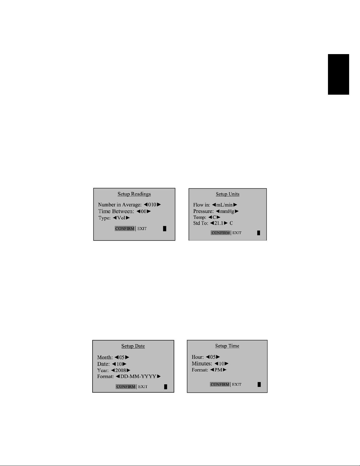
Readings
Choose the flow reading type to either volumetric ‘Vol’orstandardized‘Std’.Volumetricowistheactual
owattheambienttemperatureandpressurewhereasthestandardizedowindicatesaowrateataspecic
temperature and pressure. Standardizing pressure is set to a default value of 760 mmHg whereas standardizing
temperature is an user settable value set in ‘Std To’inthe‘Units’sub-menu.
Choose the number of measurements in the average from one to 100.
If you wish to incorporate a time delay between consecutive measurements, set Time Between from one to 60 minutes.
Set the Sensor Factor to any value from 0.200 to 3.000. Sensor factor scales the reading for calibrating MFCs
and MFMs with surrogate gases. Sensor factor effects the flow rate measurement only when the reading
‘Type’issettostandardized‘Std’
Units
Measure gas Flow in cubic centimeters, milliliters, liters or cubic feet (all units are per minute).
Measure Pressure in mmHg, kPa or PSI and Temperature in Celsius or Fahrenheit.
Set the standardizing temperature by setting ‘Std To’toavaluefrom0to50degCor32to122degF.‘Std To’effects
the flow rate measurement only when the reading ‘Type’inthe‘Reading’sub-menuissettostandardized‘Std’.
Time
Set the current time and the format.
The format can be selected as PM, AM, or 24H.
Date
Set the date and the format.
The format can be selected as DD (day)-MM (month)-YYYY (year) or MM (month)-DD (day)-YYYY (year).
2.0
6
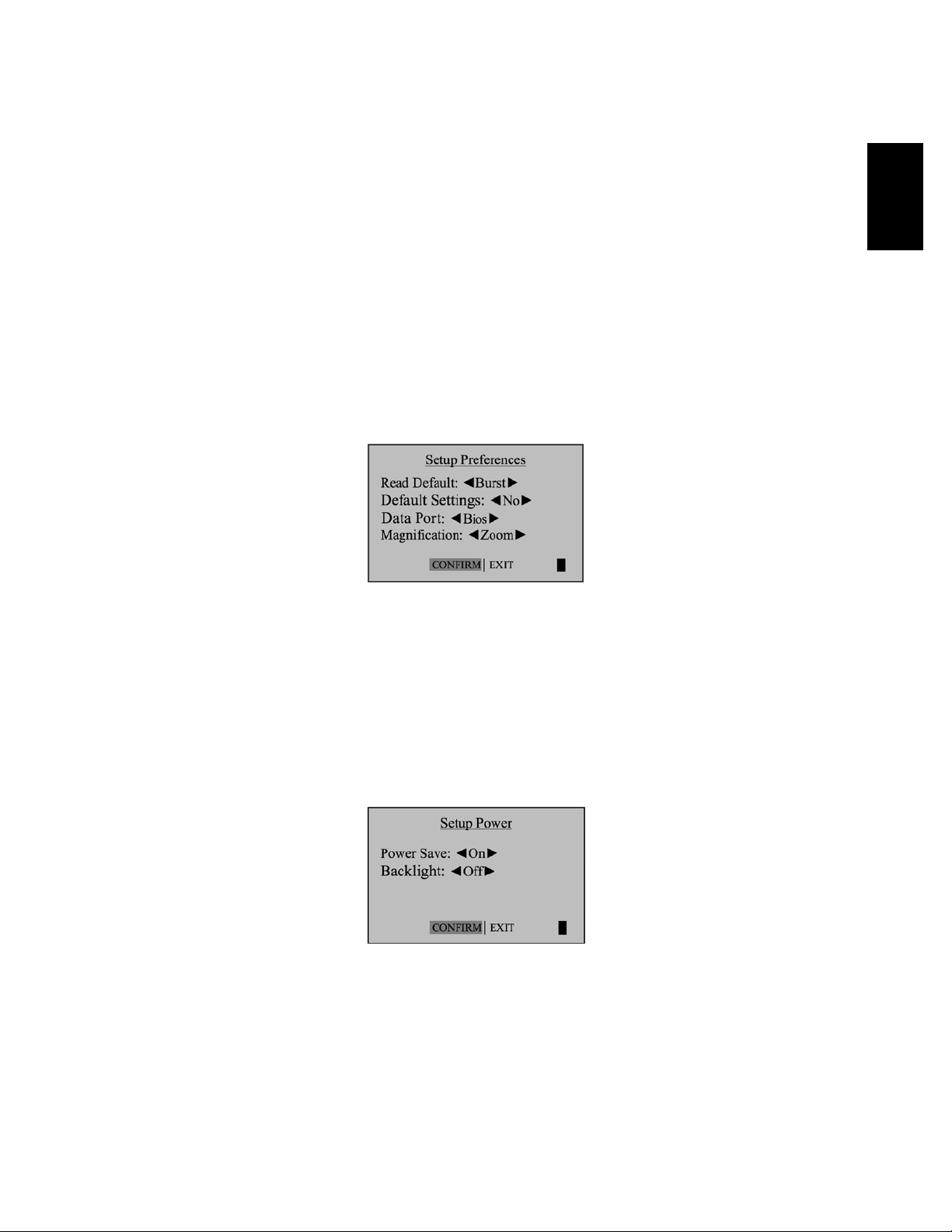
Preferences
“Read Default”
Allows you to select a preferred mode of measurement when the Defender is initially turned on.
“Default Settings”
Select<No>toallowthe‘ReadDefault’change.Selecting<Yes>willresetyourDefendertothefactorydefault
settings. See Section 8.0 for the Factory Default Settings.
“Data Port”
Set the Data Port interface by selecting: <Bios> to operate with Bios Optimizer Software <SKC> to operate with
SKC Calcheck® Interface
“Magnification”
It controls the amount of data on the display. Select <Zoom> to view only flow measurements in larger font,
or select <Detail> to simultaneously view flow measurements, temperature, and pressure in a smaller font.
Power
“Power Save”
Select<On>,yourDefenderwillsavepowerbyturningoffafterveminutesofinactivity.However,itwillnotturn
offwhenconnectedtotheACpoweradapter/charger.
Select <Off>, and your Defender will remain on until you manually turn it off.
“Backlight”
Select <On> to illuminate the LCD display or <Off > to conserve battery power.
2.0

7
Diagnostics
The Defender Leak Test is designed only to verify the internal integrity
of the instrument and alert you to an internal leak. We recommend
performing the Leak Test only as an intermediate quality control check
or whenever the integrity of the instrument is questioned due to misuse
or accidental damage.
Please note, that a leak test is not a substitute for a comprehensive
examinationoftheunit’soverallperformanceanditdoesnotensure
that your Defender is operating accurately.
• InvertyourDefenderandallowthepistontotraveltothetop
• CaptheportundertestusingtheBiossuppliedleaktestcap.
Leave the other port uncapped
• PressEnter on the control panel while the unit is still inverted
• Returntheunitupright.Theleaktestwillprogress.
About
TellsyoumoreaboutyourDefender;ausefulscreentoreferto
when speaking to a Bios technical support representative or your
Bios distributor.
Out of Range!
IftheowyouaremeasuringisoutsidetheDefender’sowrange,the“OutofRange!”warning
appears. Immediately lower or disconnect the flow. When the flow is within the proper range,
selectRESETtoclearyourDefender’slastmeasurement.
2.0

8
2.7 Measurements
Taking gas flow readings
To maintain the best possible accuracy and minimize thermal effects, Bios recommends fully charging your
battery before taking measurements. If this is not possible, we recommend disconnecting your Defender from
itsACpoweradapter/chargerwhiletakingowmeasurements—ortorungasthroughyourDefenderfor
10 minutes before starting the flow measurement.
First steps
• PresstheOn/Off button for 1 second to turn on your Defender
• Whenrstturnedon,yourDefenderdisplaysanopeningscreenshowingtheproductname,
model number and flow range
• PresstheOn/Off button for 3 seconds to turn your Defender off
Connect device to be calibrated to the appropriate Defender port.
• Connecttubingtooutletattop(suctiontting)whenadevicedrawsair(suchassampler)
• Connecttubingtobottominlet(pressuretting)fordevicesthatpushairin(pressuredevices)
• DonotcaptheunusedportontheDefender
• SelectthereadingtypetoVol or Std. Set ‘Std To’tothedesiredstandardizingtemperature
• ChoosethemeasurementtypetoSingle, Burst, or Continuous and then press Enter
2.8 Single Measurement
Each time the ‘Enter’ button is pressed, one measurement will be made. When each subsequent
measurement is made, the current flow and average of all prior readings will be displayed.
2.9 Burst Measurement
This setting functions in the same manner as ‘SINGLE’, but measurements continue automatically
until the preset number of measurements has been made. Operation then ceases and the last reading
and average are displayed.
Press Enter again to begin another preset sequence.
2.0
9
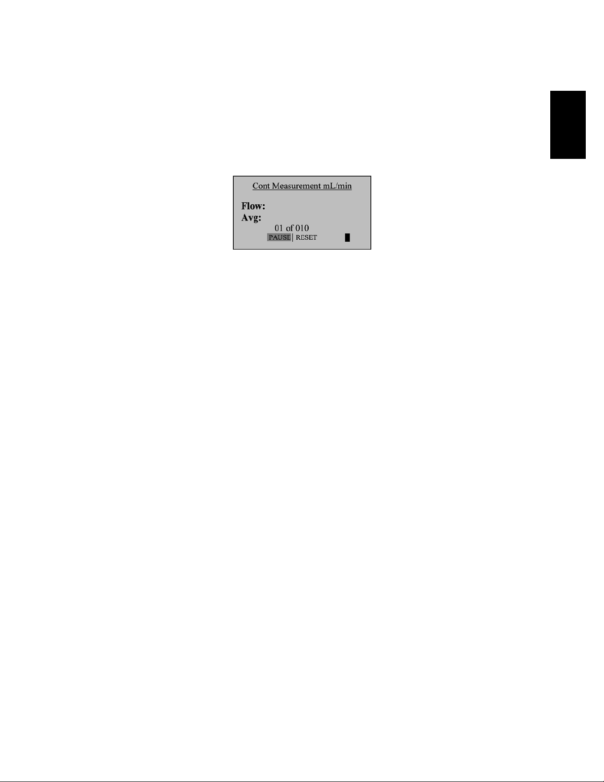
2.10 Continuous Measurement
This setting functions in the same manner as ‘BURST’, but new sequences will automatically repeat
until stopped by the user.
Note:
(010inseries)indicatesthenumberofmeasurements.10isthefactory-presetnumber.Youcandene
the number of measurement you preferred from 1 to 100 by accessing the SETUP menu
In Continuous or Burst mode, select:
• PAUSE to terminate the current flow measurement but to leave the average flow measurement
and previous flow measurement on the screen. This allows you to resume the flow measurement
sequence if you wish to do so
• RESET to terminate the flow measurement and clear the screen
2.0

10
3.1 Optimizer Collect Light Software
Your Defender 530 is supplied with Bios Optimizer Collect Light software. Bios Optimizer Collect Light
captures flow data from your Defender directly to a Microsoft Excel pre-conguredspreadsheet.
You can upgrade to Bios Optimizer Collect for more features.
TorunOptimizerCollect(upgradedversion)orCollectLight,youmusthaveaWindowsVista(32-bitversion),
Windows XP, Microsoft Excel 2000, 2003, 2007. See the optimizer CD cover for installation instructions.
3.2 Defender Firmware Upgrades
TheDefenderrmwareisupgradablethroughtheDataPort.Firmwareupgradesandproceduresforyour
Defender are available online through our website (www.biosint.com).
3.0 Data Port
3.0

11
Assuring top performance and accuracy
Your Defender is a precision measuring standard with moving parts machined to extremely close tolerances.
Variousenvironmentalfactors,productwear,driftofsensors,orinadvertentdamagemayadverselyaffect
yourDefender’smeasurementaccuracyorgeneralperformance.Forthesereasons,Bioshighlyrecommends
havingyourDefenderannuallyveriedbyanISO17025–accreditedlaboratory,suchasBios,toensureits
measurement integrity.
FortheultimateinDefendermaintenanceandtotakeadvantageofanyavailablermwareandmechanical
upgrades,Biosoffersanannualnon-mandatoryRecerticationprogram.Thisisaservicepackagethat
providescompleteproductrefurbishment,testingandavailableupgrades;calibrationandNIST-traceable
calibrationcerticates.
Recerticationincludesa90-dayservicewarrantyshouldanyrelatedlabororpartsreplacementsprovefaulty.
Turnaround time is generally two weeks from time of receipt. Expedited 48-hour turnaround is available.
4.0 Annual Maintenance and Calibration
4.0

12
Tips and guidelines for sending your Defender to Bios
IfyouaresendingyourDefenderforrepairorevaluation(ratherthanelectiveRecertication),
• ContactBiosfortechnicalsupportortroubleshootingassistancepriortoshippingtheunit.
Provide us a detailed description of your issue(s)
• Ifweareunabletoresolvethesituationbyphoneoremail,wewillissueyouanRMA(returnmerchandise
authorization) number. Follow online instruction for proper return procedure
YoucanobtainanRMAnumberthroughourautomatedweb-basedsystemathttp://www.biosint.com/
contactUs/rmaform.aspx,byemailto service@biosint.com, or by telephone at 973.492.8400. Our web site
address is www.biosint.com.
Note: Bios will not evaluate or service your instrument without an RMA number.
Ifwendtheissuesinconcernareapplicationrelatedandnotproductrelated,anevaluationfeewillbecharged.
Shipping
When shipping your Defender
• Useadequatepackingmaterial.Wheneverpossible,usetheoriginalpackingthatcamewithyour
Defender. Or use a Bios Pelican carrying case, which provides a hard case shell for protection of your
valuable equipment. If you do not already have a Bios Pelican case, visit us at www.biosint.com for
more information on obtaining one
• Useamajorfreightcarrier(e.g.,FedEx,UPS)thatsuppliestrackingnumbers
• InsureyourDefender.Biosisnotresponsiblefordamageoccurredduringtransit
• Understandourmutualshippingobligations.Biosisresponsibleforshippingcost
only if the issue is product related and the Defender is still under warranty
5.0 Shipping
5.0

13
Protecting your Defender when not in use
If you need to store your Defender for an extended period, please follow these guidelines:
1. Always store it in a clean, dry place.
2. Ifpossible,leaveitattachedtoitsACpoweradapter/chargerwhileinstorage.
3. IfyourDefendercannotbeattachedtoitsACpoweradapter/chargerwhileinstorage,pleasedothefollowing:
– Fully charge it before extended storage. If the battery is not fully charged prior to storage,
it might be permanently damaged.
4. Fully charge it at least once every three months.
5. Recharge the battery for at least 8 hours prior to reusing your Defender after storage.
6.0 Storage
6.0

14
Technical data about your Defender
Models:
530L,from5-500scc/min
530M,from50-5,000scc/min
530H,from300-30,000scc/min
Measurements:
Standardized Accuracy: ±1.2% of reading
Volumetric Accuracy: ±1% of reading
Time per Measurement: 1-15 seconds (approximate)
Type: Single, Continuous or Burst
Volumetric Flow Units:cc/min,mL/min,L/min,cf/min
Standardized Flow Units: scc/min,smL/min,sL/min,scf/min
Pressure Units: mmHg, PSI, kPa
Temperature Units: °C, °F
Basics:
Dimensions (H x W x D):5.5x6x3in/140x150x75mm
Weight:29oz/820g
Configuration: Integrated flow measuring cell,
valve and timing mechanism
Temperature & Pressure Sensors:
In the flow stream
Press Accuracy: 3.5 mmHg (typical), 7.0 mm (max)
Temp Accuracy: 0.8° C (typical), 1.3° C (max)
AC Power Adapter/Charger:12VDC,250ma,2.5mm,centerpositive
Battery:6Vrechargeable,sealedlead-acid,6-8hourstypicaloperation
Battery Operational Time (5 cycles/min): 3 hrs backlight on,
8 hrs backlight off
Pressure & Suction Fittings: ¼” ID barbed tube
Display: Backlit graphical LCD
Usage:
Flow Modes: Suction or Pressure
Operating Pressure (Absolute): 15 PSI
Operating Temperature: 0-50° C
Ambient Humidity: 0–70%, non-condensing
Storage Temperature: 0–70 °C
Warranty:1year;battery6months
Bios Optimizer Software:
RequiresWindowsXPorWindowsVista(32-bit)compatiblePCandRS-232(serial)connection
BiosOptimizerCollectLightinstallationCD(supplied);norestrictionsapply
RS-232 cable (supplied) for Defender 530 data port to PC RS-232 (serial) port connection
PC Card (optional and as necessary) creates an RS-232 port on your PC
Licensed upgrade to full collect is available
7.0 Defender 530 Series Specifications
7.0

15
The Defender is set with the following Default settings from the factory:
• Reading Type–Vol
• Number in Average – 10
• Time Between – 0
• Flow Units–cm/min
• Pressure Units – mmHg
• Temperature Units – C
• Standardizing Temp – 21.1 C
• Measurement Mode – Single
• Magnification – Zoom
• Backlight – On
• Power Save – On
• Time Format – 24H
• Date Format – MM-DD-YYYY
8.0 Factory Default Settings
8.0

16
The Bios Defender 500 Series is warranted to the original end user to be free from defects in materials and
workmanship under normal use and service for a period of one year from the date of purchase as shown on the
purchaser’sreceipt.TheDefender500Series’batteryiswarrantedforsixmonthsfromtheoriginalpurchasedate.
If the unit was purchased from an authorized reseller, a copy of an invoice or packing slip showing the date of
purchase may be required to obtain warranty service.
The obligation of Bios International Corporation under this warranty shall be limited to repair or replacement
(at our option), during the warranty period, of any part that proves defective in material or workmanship
under normal use and service, provided the product is returned to Bios International Corporation,
transportation charges prepaid.
Notwithstanding the foregoing, Bios International Corporation shall have no liability to repair or replace
any Bios International Corporation product:
1. That has been damaged following sale, including but not limited to damage resulting from improper
electricalvoltagesorcurrents,defacement,misuse,abuse,neglect,accident,re,ood,terrorism,
act of God or use in violation of the instructions furnished by Bios International Corporation
2. When the serial number has been altered or removed
3. That has been repaired, altered or maintained by any person or party other than Bios International
Corporation’sownservicefacilityoraBiosauthorizedservicecenter,shouldonebeestablished.
This warranty is in lieu of all other warranties and all other obligations or liabilities arising as a result of
anydefectordeciencyoftheproduct,whetherincontractorintortorotherwise.Allotherwarranties,
expressedorimplied,includinganyimpliedwarrantiesofmerchantabilityandtnessforaparticular
purpose,arespecicallyexcluded.
In no event shall Bios be liable for any special, incidental or consequential damages for breach of this or
any other warranty, express or implied whatsoever.
9.0 Limited Warranty
9.0

17
Bios is ready to help you with any operational issue you may encounter with your Defender. However, we may
be able to save you some time by providing a short checklist of the questions most commonly asked of our
customer service and technical specialists.
Why won’t my Defender turn on?
If the Defender will not turn on, verify that the battery has been charged. When connected to the AC power adapt-
er/chargerandpowerispresent,asmallgreenindicatorlightshouldbevisiblethroughthefrontviewingwindow.
My Defender won’t respond to push-button commands
If the Defender fails to respond to push-button commands, you can perform a hard reset of the Defender.
This can be done by inserting a paper clip into the reset opening in the back of the unit.
I am not sure I have my Defender connected properly
VerifythattheowsourceisconnectedtothepressureportofyourDefenderforpressuresourcesortothe
suction port for verifying suction pumps. The unused port should be at atmospheric pressure with any cap
or plug removed. If you are calibrating a gas that requires an exhaust line to vent the measurement gas,
ensurethatthetubingisofsufcientdiameternottocreateapressuredropgreaterthen5inchesofwater.
How do I protect against leaks?
Ensurethathoseandtubettingsaretightandleakfree.
The tubing connecting your flow source (pump, mass flow controller, needle valve, sonic nozzle or restrictor)
to the meter should be kept as short as possible.
What do I do when my leak test fails?
First check to make sure that the leak test cap is on correctly and it is not leaking through the leak test cap
itself. If the leak test cap is correct, perform leak test both at the pressure and suction side. If it fails, contact
Bios technical support.
What is the best way to connect to the filter medium?
Whencalibratingsamplingpumps,bestresultsareobtainedwiththeltermediumconnectedtothepump
andtheDefender’ssuctionportconnectedtotheinletsideoftheltermediumwithashortpieceoftubing.
Why am I experiencing a temperature increase in my Defender 530?
A temperature rise during initial battery charging, or while charging a fully discharged battery is normal.
To maintain the best possible accuracy, Bios recommends fully charging your battery before taking measurements.
Ifthisisnotpossible,werecommenddisconnectingyourDefenderfromitsACpoweradapter/chargerwhiletak-
ing flow measurements – or to run gas through your Defender for 10 minutes before starting the flow measure-
ment.
10.0 Troubleshooting Guide
10.0

18
Why doesn’t my piston return to the bottom of the cell?
If the piston fails to return to the bottom of the cell after a measurement this could be caused by:
• Adischargedbatterynotprovidingenoughpowertooperatetheinternalvalveproperly(trycharging
the Defender)
• Brightlightshiningintotheunitresultinginanoverloadoftheinternalopticalsensors(trytooperatetheunit
in a shaded location)
• Moistureordirtinsidethecell(returntheDefendertoBiosforservice)
What is dead volume ?
Dead volume is the gas volume between a flow generator and the instrument taking the measurement. Since
gas is compressible, this gas can act as a spring between the flow source and the measurement instrument.
For best accuracy this volume should be kept to a minimum.
We recommend keeping the tubing length between the gas flow generator and your Defender to no more then
0.5meters/20inchesinlength.
What is the difference between volumetric flow and standardized flow?
As we know from the ideal gas law, the volume of a gas changes with a change in temperature or pressure
even when the number of molecules which constitute the mass remains the same.
Volumetricowrateistherateatwhichavolumeofagastravelspastagivenlocation.
Volumetric Flow = As Measured Volume of Gas / Time
Standardized (mass) flow rate is expressed as the rate at which the volume of a gas travels past a given
locationifthegasisataspeciedtemperatureandpressure.Fromtheidealgaslawifthetemperature
and pressure are held constant, the volume of the gas is proportional to the number of molecules.
Standardized Flow = Volume of Gas (at the standard temperature and pressure) / Time
10.0
This manual suits for next models
3
Table of contents
Other BIOS Test Equipment manuals


