Pintek DP-40K User manual

DP-40K
差動測試棒
HIGH VOLTAGE DIFFERENTIAL PROBE
INSTRUCTION MANUAL
使用說明書
40 KVp-p / 75 MHz
1. FEATURES
2. SPECIFICATIONS
3. PANEL DESCRIPTION
4. OPERATING ENVIRONMENTAL CONDITIONS
5. OPERATING PROCEDURE
6. EXT. POWER SOURCE
7. VOLTAGE DERATING CURVE
8.MAINTENANCE
9. CLEANING
10. WARRANTY
11. REPAIR
2
TABLE OF CONTENTS / 目次
1. 簡述
2. 規 格
3. 測試棒面板說明
4. 操作環境及狀況
5. 操作程序
6. 外接電源
7. 耐壓曲線
8. 維護
9. 清潔
10. 保固
11. 維修
2
3
4
4
5
7
7
7
7
9
9
11
11
12
13
14
14
14
14
10
7
! Differential Voltage Probe,
Read the instructions before using the instrument:
1.Must acquire a differential voltage probe & get the best service
from instrument.
2.Read carefully the USER MANUAL.
3.Respect the safety precautions.
! SAFETY PRECAUTIONS
Warning, Risk of Electric Shock,
Respect the max input voltages
1.Max differential voltage: 40 V (DC + AC peak) or 14 KV RMS
2.Max voltage between each input terminal and ground: 10KV RMS
Do not use the probe in damp environment or where there is
risk of explosion.
Do not use the probe with its case open.
Disconnect the inputs and outputs of the probe before
opening the case.
! TO ORDER Differential Voltage Probe and Accessories:
An Insulated BNC/BNC lead and two 4 mm, length 3 inches(BP-
250).
Supplied a Adapter preset 9 V DC[115 V(SP-115) or 230 V(SP-
230)]
2 x high voltage IC clips(BP-266N.)
2 x Banana to Banana high voltage plug(BP-366A).
2 x Alligator plug(BP-276N).
Instruction Manual.
1

DP-40K HIGH VOLTAGE DIFFERENTIAL PROBE
1. FEATURES
The DP-40K differential voltage probe provides a safety means of
measuring floating potentials for all models of oscilloscopes
incomplete safety (MAX. Bandwidth: 75 MHZ).
It converts the high differential voltage (≦ 40 KV peak) into a low
voltage (≦ 4.0 V) with reference to the earth for display on the
oscilloscopes. It is designed specially for high voltage using.
The BNC output is designed to operate on an input with an
impedance of 1 MΩ. It is 2 times of the 50 Ω.
DP-40K can observe more exact measured testing voltage from
DMM. (Oscilloscope accuracy is 3%, and DMM is 10 times).
2. SPECIFICATIONS
(1) Bandwidth:
DC - 75 MHz (-3 dB) for x 500
DC - 20 MHz (-3 dB) for x 5000
(2) Attenuation: x 500, x 5000
(3) Accuracy: ± 2%
(4) Voltage Input Ranges (DC + AC peak to peak)
≦ 40 KV for x 5000, (i.e about 14 KV RMS or ± 20 KV DC)
≦ 4 KV for x 500, (i.e about 1.4 KV RMS or ± 2 KV DC)
(5) Permitted Max Input Voltage
Max differential voltage: 40 KV (DC + AC peak to peak)
Max voltage between each input terminal and ground: 10 KV RMS
(6) Input Impedance:
Differential: 108.8 MΩ // 1 pF
Between terminals and ground: 54.4 MΩ // 2 pF
(7) Output: ≦ ± 4.0 V
(8) Output Impedance: 50 Ω
(9) Rise Time: 4.7 ns for x 500 , 17.5 ns for x 5000
2

3
DP-40K Instruction Manual
(10) Rejection Rate on Common Mode:
60 Hz: > 80 dB , 100 Hz: > 60 dB , 1 MHz: > 50 dB
(11) Power Supply: External 9 V DC power supply.
(12) Consumption: 120 mA max (1.1 WATT)
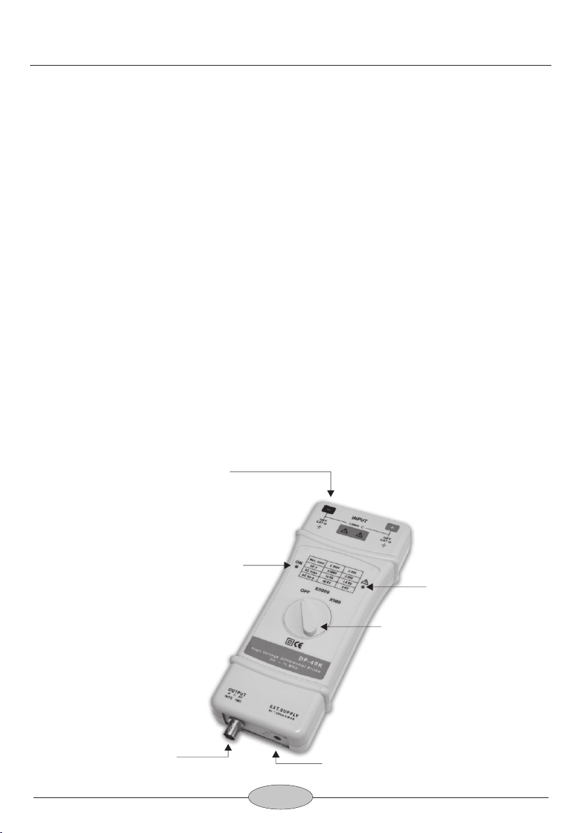
3. PANEL DESCRIPTION
Over Range Indicator
Input Connector
Output Connector External Power Source
Attenuation Function Switch
Power Indication
(1) Please DO NOT hold the probe itself when measuring the high
voltage is over 1 KV. Please put the probe itself on the working
table.
(2) Please DO NOT measuring home electricity (including two-phase
electricity and three-phase electricity).
(3) Please let the probe has 30 minutes rest after having a 5 minutes
normal measurement for over DC 10 KV or AC 7 KVRMS. It is
able to give time for internal high voltage resistors to cool down.
CAUTION!

4
5. OPERATING PROCEDURE
!Connect to leads to the input and place the wire-grip on the
circuit to be tested.
!Connect the probe to the oscilloscope with the insulated
BNC/BNC lead.
!Adjust the vertical zero adjustment of the oscilloscope if
necessary.
!Select the attenuation ratio* and the vertical deviation of the
oscilloscope in accordance with the conversion table below.
!NB: The POWER light must come on.
The conversion table gives the real vertical deviation.
MAX Voltage Input Range
(DC+AC Peak)
x 5000 40 KVp-p
4 KVp-p
4. OPERATING ENVIRONMENTAL CONDITIONS
(1) Dimensions and Weight:
218 x 83 x 30 mm; 390 g
(2) Electrical Safety to IEC 1010-1
!Dual Insulation
!Installation Category III
!Degree of Pollution 2
!Rated Voltage or Max Live-Earth: 10 KV RMS
(3) CE Mark
Conforms to EN 50081-1 and 50082-1 standards
Temperature
Relative Humidity
Reference Use Storage
+20°C … +30°C
70 % RH
0°C … +50°C
10 % … 85 % RH
-30°C … +70°C
10 % … 90 % RH
Attenuation
x 500
AC RMS
MAX Input
14 KVrms
1.4 KVrms
DCV
MAX Input
± 20 KV
± 2 KV
DP-40K Instruction Manual

5
[N.B]
The real vertical deviation in V/div is equal to the attenuation
factor multiplied by the range of vertical deviation selected on the
oscilloscope. It will be doubled in the case of use of a 50 Ω load.
Example:
With the probe on factor x 500, the oscilloscope on 1 V/div, the
real vertical deviation is 500 x 1 V/div = 500 V/div.
With a 50 Ω load on the input of the oscilloscope the deviation
becomes: 500V/div x 2 = 1KV/div.
x 5000 Range
Real Deviation In V/div
1
x 500 Range
2.5 KV0.5 250 V
1 KV0.2 100 V
500 V0.1 50 V
250 V50 m 25 V
100 V20 m 10 V
50 V10 m 5 V
25 V5 m 2.5 V
10 V2 m 1 V
6. EXT. POWER SOURCE
! Power consumption of the probe are 120 mA, thus it not suit for
battery, please use the accessory adapter only.
! If there are any damage on the adaptor, please contact us and use
the adaptor supply by us only. If the input power over 12 V DC will
caused to the probe hard damage.
Vertical Deviation on the
Oscilloscope in V/div
5 KV 500 V
DP-40K Instruction Manual
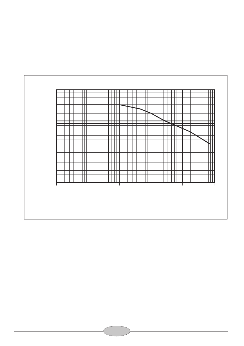
7. Voltage Derating Curve
DP-40K Instruction Manual
6
Frequency (Hz)
Voltage(DC+ACp-p)
100V
1K 10K 100K 1M 10M 100M
1KV
30KV
100KV
40KV
100 KHz / 40 KVp-p, 500 KHz / 30 KVp-p, 1 MHz / 20 KVp-p,
3 MHz / 10 KVp-p, 20 MHz / 5 KVp-p, 75 MHz / 2 KVp-p
20KV
10KV
5KV
2KV
3M 20M 75M500K

8. MAINTENANCE
For maintenance, only use specified spare parts.
The manufacturer can not be held responsible for any accident
arising following a repair made other than its after sales service or
approved repairers.
9. CLEANING
This probe does not require any particular cleaning. If necessary,
clean the case with a cloth slightly moistened with soapy water.
10. WARRANTY
Unless notified to the contrary, our instruments are guaranteed
against any manufacturing defect or material defect. They do not
bear the specification known as the safety specification. Our
guarantee, which may not under any circumstances exceed the
amount of the invoiced price, goes no further than the repair of our
faulty equipment, carriage paid to our workshops.
11. REPAIR
Maintenance, repairs under or out of guarantee. Please return to
product to your distributor.
7
DP-40K Instruction Manual

差動測試棒,
!使用前請詳細閱讀使用說明
1.請先獲得⼀⽀差動測試棒
2.從使⽤說明取得最佳維修及服務
3.請詳讀使⽤者操作⼿冊
4.請注意安全注意事項
!安全注意事項:
請⼩⼼注意觸電!
請注意最⾼輸⼊電壓!
最⾼差動電壓:40KV(DC+ACpeak)或14KVRMS
輸⼊端及接地端間的最⼤差動電壓:10KVRMS
請勿使⽤此產品在潮濕的環境下或有易爆的⾵險下操作!
請勿使⽤此產品當此產品的盒蓋被打開!
當打開此產品的盒蓋時請將輸出及輸⼊端切斷!
!訂購差動測試棒時內含
雙端BNC接頭的測試纜線,⾧度3英呎(BP-250)
⼀個9VDC轉換器[客⼾必需指定115V(SP-115)或230V(SP-230)]
⼀對⾼電壓專⽤的IC夾(BP-266N)
⼀對指定規格的雙端⾹蕉插頭⾼電壓傳輸線(BP-366A)
⼀對⾼電壓專⽤的鱷⿂夾(BP-276N)
使⽤說明書
8

DP-40K 差動測試棒
1.簡述:
DP-40K差動測試棒提供⼀個安全的絕緣儀器給所有的⽰波器使
⽤,它可以轉換由⾼輸⼊的差動電壓(≦40KVPEAK)進⼊⼀個低
電壓(≦4.0V),並且顯⽰波形在⽰波器上,使⽤頻率⾼達75MHz,
是⾼電壓專⽤型。
差動測試棒輸出標⽰是設計在操作⽰波器1MΩ的輸⼊阻抗的相
對衰減量,當使⽤50Ω匹配器時衰減量剛好為2倍量。
DP-40K差動測試棒,也建議在數字電表上觀測更精確的實際測試
電壓值(⽰波器精確度為3%,數字電表約精準10倍)。
2.規格:
(1)頻寬:DC-75MHz(-3dB)forx500檔
DC-20MHz(-3dB)forx5000檔
(2)衰減:共2檔(x5000,x500)
(3)精確度:±2%
(4)輸⼊電壓範圍(DC+ACPEAKTOPEAK)
≦40KVforx5000,(約14KVRMS或±20KVDC)
≦4KVforx500, (約1.4KVRMS或±2KVDC)
(5)允許最⾼輸⼊電壓:
最⾼差動電壓:40KV(DC+ACPEAKTOPEAK)
輸⼊端及接地端間最⾼電壓:10KVRMS
(6)輸⼊阻抗:
差動:108.8MΩ//1pF
單端到接地端間的輸⼊阻抗:54.4MΩ//2pF
(7)輸出電壓:≦±4V
9
3. 測試棒面板說明
(8)輸出阻抗:50Ω
(9)上升時間:4.7nsforx500檔,17.5nsforx5000檔
(10)雜訊抑制率:
60Hz:>80dB;100Hz:>60dB;1MHz:>50dB
(11)電源:指定外接9VDC電源(必須使⽤本公司指定品)
(12)耗電:最⼤耗電量120mA(1.1⽡特)
輸入端
過載指式燈
衰減量選擇及電源開關旋鈕
電源指示燈
外部電源引入端
輸出端
DP-40K 中文說明書
10
(1) 量測1 Kv以上⾼壓時, 請勿⼿持本機, 建議平放於⼯作桌使⽤。
(2) 市電量測 (包含雙相電, 三相電) , 嚴禁超過10 KVRMS。
(3) ⼀般測量超過DC 10 KV 或AC 7 KVRMS, 請量測五分鐘, 休息
30分鐘。讓內部⾼壓電阻有⾜夠時間散熱。
安全注意事項 !

5.操作程序
!將附件BP-366N與BP-266N(或BP-276N)接起來後插⼊DP-40KV
的輸⼊端,並將BP-266N(或BP-276N)與測量物接觸。
!將BP-250與DP-40K的輸出端連接,並與⽰波器連結。
!如有需要先調整⽰波器上的垂直開關。
!將⽰波器上的衰減率及垂直開關調整到⼀致的位置,如下表。
!注意:電源必須打開。
4.操作環境及狀況
(1)尺⼨及重量:218x83x30mm;390g
(2)電⼦安全規範IEC1010-1
!雙絕緣
!安裝類⽬III
!污染程度2
!相關電壓或最⼤接地:10KVRMS
!CE:EN50081-1及50082-1
溫度
溼度
一般狀態 使用操作中 儲存
+20°C … +30°C
70 % RH
0°C … +50°C
10 % … 85 % RH
-30°C … +70°C
10 % … 90 % RH
11
DP-40K 中文說明書
x 5000 40 KVp-p
4 KVp-p
x 500
最大輸入
AC RMS
14 KVrms
1.4 KVrms
最大輸入
DCV
± 20 KV
± 2 KV
衰減 最大輸入電壓
(DC+AC Peak)

[注意]
實際的垂直偏向是等於衰減乘上⽰波器上所選擇的垂直偏向.如
果另外使⽤50Ω負載端⼦時,實際電壓值剛好是2倍量。
例如:
測試棒是x500,⽰波器的垂直偏向在1V/div,其實際的垂直偏向
為:500x1V/div=500V/div
若⽰波器輸⼊的負載是50Ω,偏向就為:
500V/divx2=1KV/div
示波器上的
垂直偏向(V/DIV)
換算實際偏向(V/DIV)
6.外接電源
!本產品因耗電量⾼達120mA,因此指定使⽤電轉接器115V專
⽤(SP-115)或230V專⽤(SP-230)。
!請勿使⽤⾮本公司指定品,若因此造成任何損毀,本公司概不
負責。
12
DP-40K 中文說明書
x 5000檔
1
x 500檔
2.5 KV0.5 250 V
1 KV0.2 100 V
500 V0.1 50 V
250 V50 m 25 V
100 V20 m 10 V
50 V10 m 5 V
25 V5 m 2.5 V
10 V2 m 1 V
5 KV 500 V

13
DP-40K 中文說明書
7. 耐壓曲線
頻 率 (Hz)
電壓(直流+交流峰值)
100V
1K 10K 100K 1M 10M 100M
1KV
30KV
100KV
40KV
100 KHz / 40 KVp-p, 500 KHz / 30 KVp-p, 1 MHz / 20 KVp-p,
3 MHz / 10 KVp-p, 20 MHz / 5 KVp-p, 75 MHz / 2 KVp-p
20KV
10KV
5KV
2KV
3M 20M 75M500K

8.維護:
保養此產品時請使⽤原廠指定的⼯具.原廠將不負任何責任由其他不
被認可的維修⼈員所做的維修。
9.清潔:
此產品不需要任何特定的清潔. 如有需要, 請⽤輕軟乾淨的布沾上微量
的清潔液輕輕的在產品外觀擦拭。
10.保固:
除了在⼈為上的特意損壞,本產品是受保固並可以維修的,並不包含在
安全規範的責任。
保固是以不超出發票上的⾦額,零件的更換及運送的費⽤。
保固是僅在正常操作下⽽造成的損壞.並不包含任何刻意的損壞,操作
上的錯誤,機械上的操作不當,保養不當,負載或過壓。
原廠的保固僅包含有限的單純更換損壞的零件.使⽤者將不可歸據直接
或間接的責任在原廠。
原廠的保固是賣出後的12個⽉內.如有任意的⾮原廠的維修或更換零件,
原廠保固將⾃然取消。
11. 維修:
有任何的維修,保養或更換零件是在保固以外,請將產品退回原廠維
修。
14
DP-40K 中文說明書

Accessories 附件圖:
BP-266N BP-250
BP-366A
BP-276N
(Adapter)
115V: SP-115
230V: SP-230

TINSE22 Ver.04
Other manuals for DP-40K
1
Table of contents
Other Pintek Test Equipment manuals


Popular Test Equipment manuals by other brands


Kingfisher
Kingfisher KI7343C-InGaAs quick start guide

Fluke
Fluke 975 AirMeter Application note

Andatech
Andatech SOBERLIVE user manual

Agilent Technologies
Agilent Technologies 8156A Operating and Programming Guide

Oakton
Oakton EcoTestr pH 2 operating instructions

Dräger
Dräger Alcotest 6510 Instructions for use