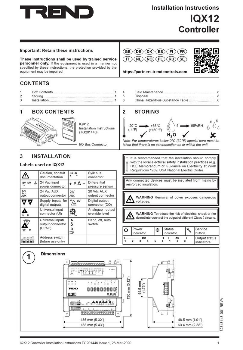
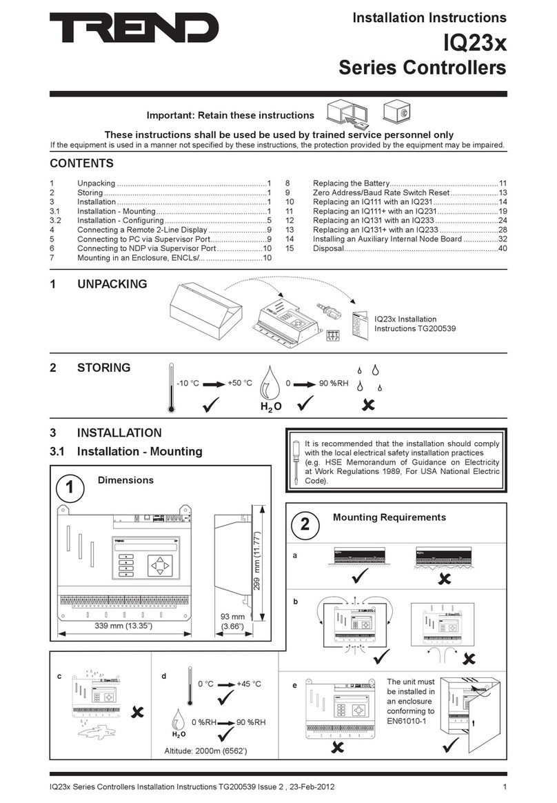
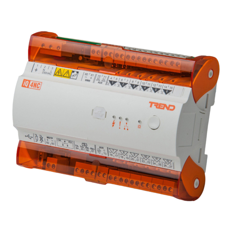
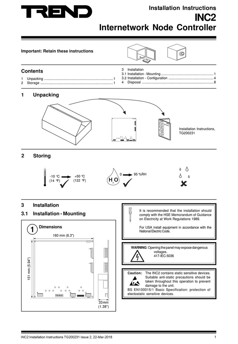
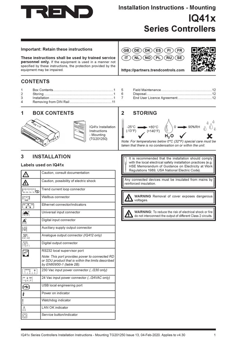
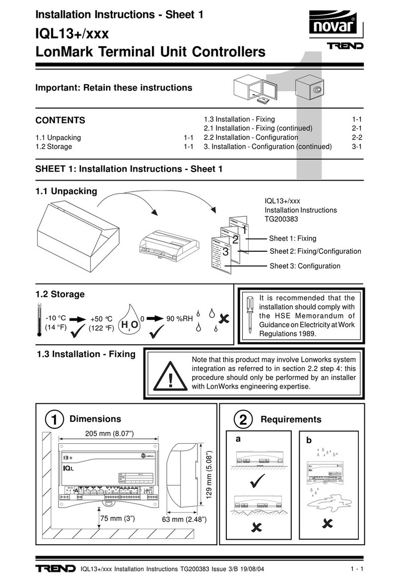
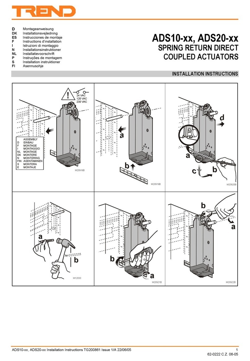
TREND IQ251 User manual

IQ251 Installation Instructions TG103483 Issue 4, 09-May-2012 1
Installation Instructions
IQ251
Controller
Important: Retain these instructions
These instructions shall be used by trained service personnel only
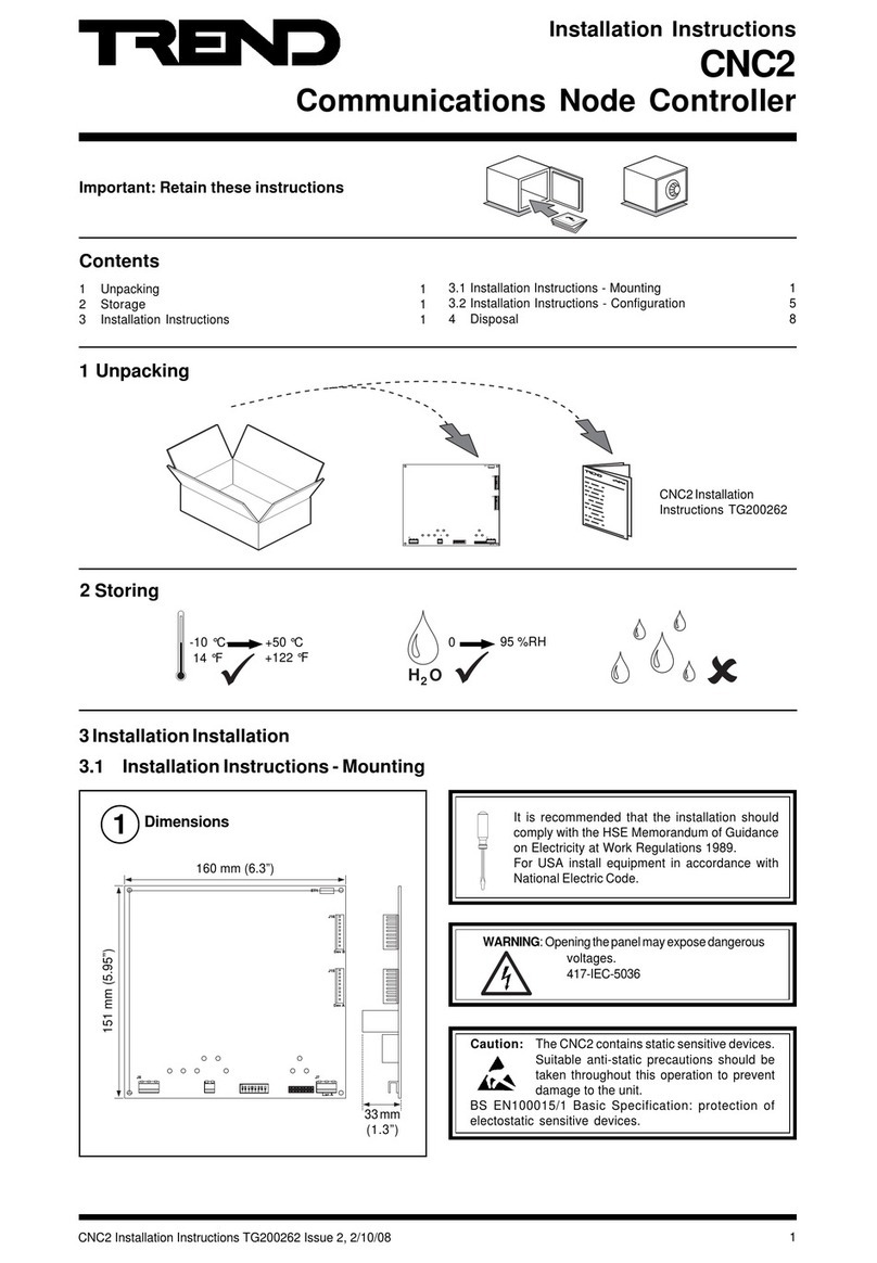
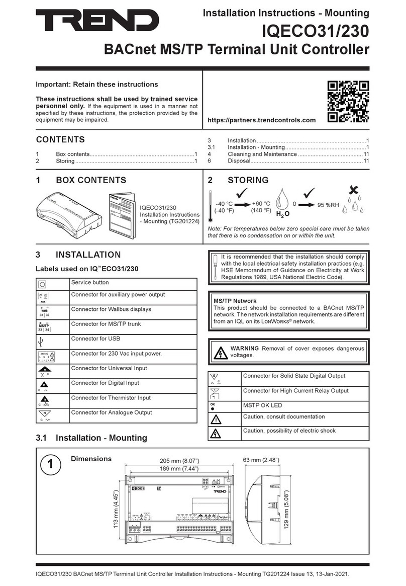
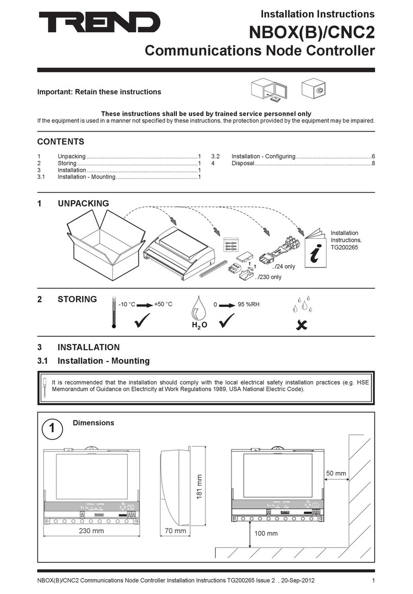
1Dimensions 2Mounting Requirements
3 INSTALLATION
3.1 Installation - Mounting
1 UNPACKING
2 STORING
It is recommended that the installation should comply
HSE Memorandum of Guidance on Electricity at Work
CONTENTS
1
1
3 Installation1
1
7
12
12
13
15
16
IQ251
Installation Instructions,
TG103483
only
HO
2
0
90 %RH
IQ251
a
IQ251
IQ251
b
e
IQ251
IQ251
in an enclosure rated to
!
IQ251
d
0 %RH 90 %RH
HO
2
c
Altitude:

2 IQ251 Installation Instructions TG103483 Issue 4, 09-May-2012
IQ251 Installation Instructions
3Mounting
4Fit earthing (grounding) bars 5Route Cables
3.1 Installation - Mounting
Wall Metal Panel rear access Metal Panel no rear access ENCLS
see section 5
a
4 holes
aa
b bTap holes
ef
IQ251
IQ251
IQ251
4 holes
4 holes
b-
M6 screws and nuts
Tap 4 M6 holes
d
cInsert lower screws cInsert lower screws cInsert lower screws
M6 screws
a
b
!

IQ251 Installation Instructions TG103483 Issue 4, 09-May-2012 3
Installation Instructions IQ251
6Tie Cables 7Remove Side Plates
8Fit I/O Modules
9Replace Side Plates 10 Terminate Screens
cleats
a
b c
IQ251
a Snap off section if required
b Select Modules
c
snap off sections
only
or
or
or
or
or
slot
d Slide into position
IQ251
2 eyelets
maximum
a b
3.1 Installation - Mounting

4 IQ251 Installation Instructions TG103483 Issue 4, 09-May-2012
IQ251 Installation Instructions
11 Connect Inputs
12 Connect Analogue Outputs
S
S
+
Thermistor Input
SIG
SIG
S
Analogue Input (AI1 to AI8)
I
IX
T
V
Analogue Output Channels (AO1 to AO8)
WARNING
+
0
2
2
recommended for all inputs
3.1 Installation - Mounting

IQ251 Installation Instructions TG103483 Issue 4, 09-May-2012 5
Installation Instructions IQ251
13 Connect Digital Outputs
14 Connect Input Power
3.1 INSTALLATION - MOUNTING
Digital Output Channels (DO1 to DO8)
n
IQ
Suppression Installation
Instructions TG200208
WARNING
n
IQ
IQ
n
n + 1
R
2
Arc suppression recommended
IQ251 Consumption <=100 VA
EJ105383
24V
Earth
if /230
if /24VAC
if /24VDC
50 to 60 Hz
50 to 60 Hz
EJ105383
24V
Earth
if /24VAC, /24VDC or /USA
DO NOT SWITCH
SUPPLY O N
/USA the input
power connections
IQ251/USA
!
if /USA
24 Vac:
24 Vdc:
24 Vac
Earth
+24V
0V
Black
Red
White
0V
WARNING:
6 IQ251 Installation Instructions TG103483 Issue 4, 09-May-2012
IQ251 Installation Instructions
15 Connect Network
16 Connect Auxiliary Output Supply
3.1 Installation - Mounting
92-1735
IQ251
polarity independent
4 wire
2
2 wire
Cable 1k2 baud 9k6 baud 19k2 baud No. of
Wires
1000 m
1000 m
700 m
2
1000 m
1000 m
500 m
2
IQ system TP/1/1/22/HF/200
1000 m
700 m
350 m
2
IQ system TP/2/2/22/HF/200
1000 m
500 m
250 m
4
24V
+
-
IQ251
+
C
AO
IQ251
24V
IN
0V
2RM
-
24V
I
2

IQ251 Installation Instructions TG103483 Issue 4, 09-May-2012 7
Installation Instructions IQ251
1Switch Off 2Isolate I/O
3Open Panel 4Disconnect I/O
5Set the Network Baud Rate 6Set the Network Address
IQ251
ADDRESS
ON
RX
TX
O
I
WARNING
WARNING
IQ251
WARNING
IQ251
IQ251
RX
TX
SET
IQ251
RX
TX
address
1, 4 to 9, 11 to 119
IQ251
3.2 Installation-Conguration

8 IQ251 Installation Instructions TG103483 Issue 4, 09-May-2012
IQ251 Installation Instructions
7Link Analogue Input Channels
8Set Digital Output Links
3.2 Installation-Conguration
I
IX
T
V
powered
powered
Thermistor
Warning: These terminals may
aidentify correct link
bset link appropriately
OI

IQ251 Installation Instructions TG103483 Issue 4, 09-May-2012 9
Installation Instructions IQ251
9Switch On 10 Check Controller
11 Check Network
WD
a PWR
power
IQ251
RX
TX
c I/O
IQ251
RX
TX
IQ251
a RX
IQ251
IQ251
3.2 Installation-Conguration

10 IQ251 Installation Instructions TG103483 Issue 4, 09-May-2012
IQ251 Installation Instructions
12 Congure
13 Test Inputs
14 Test Analogue Outputs
IQ251
IQ251
RX
TX
SET Manual TE200147
SET
IQ251
∆
ab
c d
Switch off
Switch on
IQ251
IQ251
d
ca b
Switch off Switch on
IQ251
3.2 Installation-Conguration

IQ251 Installation Instructions TG103483 Issue 4, 09-May-2012 11
Installation Instructions IQ251
15 Test Digital Outputs
16 Backup
17 Close Panel
d
c
ab
Switch off Switch on
O
I
IQ251
IQ251
IQ251
e
SET Manual TE200147
SET
IQ251
IQ251
IQ251
RX
TX
IQ251
Equipment
I
Equipment
3.2 Installation-Conguration

12 IQ251 Installation Instructions TG103483 Issue 4, 09-May-2012
IQ251 Installation Instructions
1Open Door 2Drill Wall
3Mount on Wall 4Remove Backplate
5Mount IQ251 on Backplate 6Replace Backplate
1Connect RS232 2CongureAddress
4 MOUNTING IN A ENCLOSURE, ENCLS/...
5 CONNECTING TO PC USING SUPERVISOR PORT
screws
ba
ba c
IQ251
RX
TX
SET or
IQ251

IQ251 Installation Instructions TG103483 Issue 4, 09-May-2012 13
Installation Instructions IQ251
1Upload Strategy
2Switch
Off 3Isolate I/O 4Open Panel
5Unscrew Main Cover 6Lift Off Cover
6 REPLACING THE BATTERY
SET Manual TE200147
SET
IQ251
IQ251
IQ251
RX
TX
SUPERVISOR
IQ251
WARNING
panel may expose
IQ251
ADDRESS
ON
RX
TX
O
I
WARNING
CAUTION
!

14 IQ251 Installation Instructions TG103483 Issue 4, 09-May-2012
IQ251 Installation Instructions
8Replace Battery 9Replace Cover
10 Screw on Main Cover 11 Switch On
12 Wait
13
14 Download Strategy
15 Close Panel 16 Reconnect Power to I/O
6 REPLACING THE BATTERY
10 S
IQ251
SET Manual TE200147
IQ251
SET
Reset
SUPERVISOR
IQ251
WARNING
!

IQ251 Installation Instructions TG103483 Issue 4, 09-May-2012 15
Installation Instructions IQ251
1Backup,
Switch Off,
Isolate,
Open Panel
2Note the Network Address and Baud Rate
3Set all Switch Poles to Zero 4Switch On
6Reset the Network Baud Rate 7Reset the Network Address
5Wait for Relays
8Download Strategy, Close Panel, Reconnect Power to I/O
7 ZERO ADDRESS/BAUD RATE SWITCH RESET
IQ251
RX
TX
IQ251
RX
TX
IQ251
RX
TX
IQ251
RX
TX
SET
Address = 0 Baud = 0
SET
address
1, 4 to 9, 11 to 119
IQ251

16 IQ251 Installation Instructions TG103483 Issue 4, 09-May-2012
IQ251 Installation Instructions
© 2012
Trend Control Systems Limited
Trend Control System USA
1Switch Off, Isolate, Open Panel, Remove Cover
2Replace Fuse
3Replace Cover 4Close Panel
6Reconnect Power to I/O
5Switch On
WEEE Directive:
9 DISPOSAL
8 REPLACING THE FUSE
1¼”
IQ251
a b c
Other manuals for IQ251
1
Table of contents
Other TREND Controllers manuals

TREND
TREND IQX12 User manual

TREND
TREND IQ4E User manual

TREND
TREND IQ41 Series User manual

TREND
TREND AL0620-24-K User manual

TREND
TREND IQ422 User manual

TREND
TREND IQ3xcite User manual

TREND
TREND INC2 User manual

TREND
TREND IQ3 series User manual

TREND
TREND AD05-24 Operation manual

TREND
TREND NBOX(B)/CNC2 User manual
Popular Controllers manuals by other brands

Danfoss
Danfoss Vacon NXP Series operating guide

Emerson
Emerson Dixell XR10C Installating and operating instructions

Spid Elektronik
Spid Elektronik MD-01 user manual

YASKAWA
YASKAWA motoman NX100 instructions

industrie technik
industrie technik CMF10 quick start guide

Erreka
Erreka ROLL 60C Installation instruction