artisan 5400-ES User manual

Notice: Artisan Controls Corporation assumes no responsibility for customers applications or product design. The information and data contained herein is the sole and
exclusive property of Artisan Controls Corporation. Any duplication, misuse, or conversion of this information without the express written consent of Artisan Controls
Corporation is illegal and will result in damages including court costs and attorney fees being assessed against the party misusing this property
Artisan Controls Corporation, 111 Canfield Ave., Bldg B15-18, Randolph, NJ 07869
www.artisancontrols.com
5400-E & -ES Event Controller User’s Manual
Table of Contents
Page 1
V1.08
SCREENS & FUNCTIONS
Table Of Contents
INTRODUCTION
. . . . Main Screen
2
2
2
3
4
5
6
7
8
9
10
11
12
13
14
14
15
16
17
18
. . . . Setting Time & Date
. . . . Schedules
. . . . Schedule Editing
TECHNICAL DATA
. . . . 5400-E Dimensions
. . . . 5400-E Wiring
. . . . Specifications
. . . . Event Editing
. . . . Schedule Copy & Delete
. . . . Configuring Security & Outputs
. . . . USB Import & Export
. . . . Holidays
. . . . Main Menu
. . . . System Inputs & Outputs
5400-E
5400-ES
. . . . Daylight Savings Time
. . . . 5400-ES Dimensions
. . . . 5400-ES Wiring

Notice: Artisan Controls Corporation assumes no responsibility for customers applications or product design. The information and data contained herein is the sole and
exclusive property of Artisan Controls Corporation. Any duplication, misuse, or conversion of this information without the express written consent of Artisan Controls
Corporation is illegal and will result in damages including court costs and attorney fees being assessed against the party misusing this property
Artisan Controls Corporation, 111 Canfield Ave., Bldg B15-18, Randolph, NJ 07869
www.artisancontrols.com
5400-E & -ES Event Controller User’s Manual
Table of Contents
Page 2
V1.08
INTRODUCTION
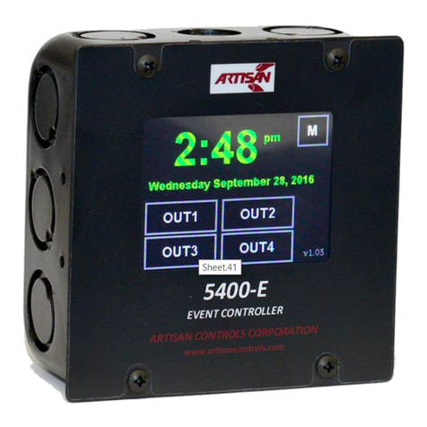
The Artisan Controls Model 5400-E and 5400-ES event and bell controllers provide a modern graphical user
interface via it’s 3.5" diagonal color display and includes two relay contact outputs, two DC outputs for
driving solid state relays, two switch inputs, and a USB port for importing and exporting the controller
configurations. The 5400-ES uses the two DC output to drive additional relays.
MAIN SCREEN
The main screen of the controller indicates the current time and date, the state of the four outputs, function
flags that indicate whether the controller is running the output schedules, has security enabled for accessing
the controller schedules and configuration, and whether holidays are enabled and active.
Function Flags -
blank or [RUN]= Controller outputs are activating according to their schedules.
[RUN]= Controller outputs are disabled.
blank = No access code required for menu access.
[SEC]= Either the switch input is closed or the controller will require entering an access code.
[SEC]= Aswitch input needs to be closed to gain access.
[DST]= Daylight Savings Time is enabled, [DST]= is it disabled.
blank = Holidays not enabled or active.
[HOL]= Holidays have been enabled and the outputs are active
[HOL]= Today is configured as a holiday and the outputs are inactive.

Notice: Artisan Controls Corporation assumes no responsibility for customers applications or product design. The information and data contained herein is the sole and
exclusive property of Artisan Controls Corporation. Any duplication, misuse, or conversion of this information without the express written consent of Artisan Controls
Corporation is illegal and will result in damages including court costs and attorney fees being assessed against the party misusing this property
Artisan Controls Corporation, 111 Canfield Ave., Bldg B15-18, Randolph, NJ 07869
www.artisancontrols.com
5400-E & -ES Event Controller User’s Manual
Table of Contents
Page 3
V1.08
MAIN SCREEN (cont)
Time and Date -
To update the time and/or date simply touch either the time or
date on the main screen and this window appears:
To change any item (other than the am/pm) simply touch the
item and it is highlighted in green. The window to the right
shows the hours being highlighted. To change the value use the
plus and minus buttons on the right side. To change the am to
pm and vice versa simply touch the item and it toggles back
and forth.
Output Buttons -
Touching any of the output buttons displays the events in its
schedule, this event occurs at 7:00 am, the output is turned
ON, and this happens Monday thru Friday but not on Saturday
or Sunday. More details about events are in the Scheduling
section later in this manual.
Touching and holding an output button for two seconds until it
double chirps manually changes its state from on to off or off
to on.
To exit without changing press the red X in the upper right hand corner. to save the new values press the
[SAVE] button. The system save the new values and return to the main screen.
Buttons for outputs which are turned on are filled with green, otherwise they are black. Outputs whose
schedules are disabled will be black and there will be no name visible in the button . Disabled outputs
cannot be changed by holding their buttons down nor are their schedules available for viewing .
Main Menu Button -
Pressing the [M] button in the upper right hand corner will access the Main Menu screen from which the
output schedules are managed, holidays can be configured, the controller security and input functions can
be configured, and the controller configurations and schedules can be imported and exported.

Notice: Artisan Controls Corporation assumes no responsibility for customers applications or product design. The information and data contained herein is the sole and
exclusive property of Artisan Controls Corporation. Any duplication, misuse, or conversion of this information without the express written consent of Artisan Controls
Corporation is illegal and will result in damages including court costs and attorney fees being assessed against the party misusing this property
Artisan Controls Corporation, 111 Canfield Ave., Bldg B15-18, Randolph, NJ 07869
www.artisancontrols.com
5400-E & -ES Event Controller User’s Manual
Table of Contents
Page 4
V1.08
MAIN MENU
If password security has been enabled the access code entry window (below) will appear requesting the 4
digit code. This screen will show the digits as asterisks for security. Pressing the [Clear] button clears the
digits already entered, pressing the [ENTER] button uses the entered digits to attempt to access the main
menu. If password security is not enabled the controller will display the main menu screen below.
MAIN MENU FUNCTIONS:
[Schedules] = Edit, copy, and delete output schedules.
[Holidays] = Configure and enable holidays
[Daylight ST] = Configure and enable Daylight Savings Time.
[Configure] = Set security code and enable/disable security, configure switch input functions, and
set the output channel names.
[USB] = Use a USB flash drive to save or read output schedules and controller configurations.
[System] = Test controller inputs and outputs, reset back to factory defaults

Notice: Artisan Controls Corporation assumes no responsibility for customers applications or product design. The information and data contained herein is the sole and
exclusive property of Artisan Controls Corporation. Any duplication, misuse, or conversion of this information without the express written consent of Artisan Controls
Corporation is illegal and will result in damages including court costs and attorney fees being assessed against the party misusing this property
Artisan Controls Corporation, 111 Canfield Ave., Bldg B15-18, Randolph, NJ 07869
www.artisancontrols.com
5400-E & -ES Event Controller User’s Manual
Table of Contents
Page 5
V1.08
The 5400-E has the capacity for storing up to 128 events. Events
can be created for any output and all the events for an output is
called a schedule.
NOTE: Users of our 4950 series controllers please read this
section carefully as we have designed the events for this new
controller differently than you are familiar with on your 4950.
This one controller can perform all the function of the 4950B bell
controller, 4950H event controller, and all controllers derived
from those products!
SCHEDULES
Important Features:
1. Any number of the 128 available events can be used for an output schedule, there are no limitations.
2. Each event can be configured to be active on any or all of the days of the week.
3. The events do not have to be entered in sequence, the controller automatically sorts them into proper
time order for each output.
4. The output events and system configurations are saved in non-volatile memory which will retain your
settings for up to 10 years with no power. Losing power to the controller will not affect the schedules,
it will only affect the current time and date and only if power is off for more than 5 days.
NOTE: When saving or deleting events and schedules the controller will chirp twice to indicate that your
changes have been saved to the non-volatile memory. A long beep indicates that it was not saved and
should be tried again.
Press the [Edit Schedule] button to begin with the screen below, then press the button for the output
schedule you want to edit:

Notice: Artisan Controls Corporation assumes no responsibility for customers applications or product design. The information and data contained herein is the sole and
exclusive property of Artisan Controls Corporation. Any duplication, misuse, or conversion of this information without the express written consent of Artisan Controls
Corporation is illegal and will result in damages including court costs and attorney fees being assessed against the party misusing this property
Artisan Controls Corporation, 111 Canfield Ave., Bldg B15-18, Randolph, NJ 07869
www.artisancontrols.com
5400-E & -ES Event Controller User’s Manual
Table of Contents
Page 6
V1.08
SCHEDULE EDITING
Once you select the output to edit its schedule is displayed in
the window to the right. All the events are sorted and shown
in sequence, the up and down arrows allow you to scroll
page by page through all the events. Touching an event will
highlight it with red text on a white background.
[Add] = Create a new event and add it to the schedule.
[Edit] = Edit the highlighted event.
[Copy] = Copies the highlighted event to a new event
[Del]= Deletes the highlighted event.
The [ON]button indicates that this output schedule is active. Touching this button disables the schedule,
the button turns black and the text changes to [OFF]. Touching the button again re-enables the schedule,
the button turns green and the text changes to [ON].
Touching the [Add], [Edit], or [Copy] buttons displays the event editing window:

Notice: Artisan Controls Corporation assumes no responsibility for customers applications or product design. The information and data contained herein is the sole and
exclusive property of Artisan Controls Corporation. Any duplication, misuse, or conversion of this information without the express written consent of Artisan Controls
Corporation is illegal and will result in damages including court costs and attorney fees being assessed against the party misusing this property
Artisan Controls Corporation, 111 Canfield Ave., Bldg B15-18, Randolph, NJ 07869
www.artisancontrols.com
5400-E & -ES Event Controller User’s Manual
Table of Contents
Page 7
V1.08
EVENT EDITING WINDOW
Day of the Week:
The day of the week buttons allow you to enable this event for
any of the days in the week, [S] = Sunday, [M] = Monday, etc. A
green button indicates that this event will be active that day,
black means that it is not. Touch the button to change that day
between its active and inactive states.
Event Hour and Minute:
Touching the hour or minute item highlights it, then use the plus
and minus buttons to change the value. Touching the [am] button changes it to [pm] and vice versa.
Output State:
The output state button is either [ON] and green or [OFF] and red:
[ON]= Output turns ON when the event is activated.
[OFF]= Output turns OFF when the event is activated.
Event Duration:
The event duration determines how long the output stays in that state:
1. An event duration of 0 means that the output goes to the programmed state and stays in that state until
another event changes it.
2. An event duration greater than 0 means that the output will take the programmed state for that length
of time in second or minutes then change back.
Press the red X to exit without saving, press [SAVE] to save the event and return to the schedule window.
Event Programming Notes:
Event durations of 0 (state changes) are most useful when you want to turn something on in the morning
(such as an elevator or a coffee pot) and turn it off at night. This requires two events, one to turn the
output ON and another to turn it OFF.
Non-zero event durations are useful for programming bell sequences for schools or factories . You can
program an output to turn on for 5 seconds 10 minutes before the end of a period, and then for 10 seconds
when the period ends.
Programming Tip –When programming for bell sequences you can use the [Copy] button to make it easier
to create your events. Create the first bell event, configuring your time, duration, and active days and save
it. Then highlight it in the event list and press [Copy]. The original event is copied to a new event so all you
need to do is change the time and save it!

Notice: Artisan Controls Corporation assumes no responsibility for customers applications or product design. The information and data contained herein is the sole and
exclusive property of Artisan Controls Corporation. Any duplication, misuse, or conversion of this information without the express written consent of Artisan Controls
Corporation is illegal and will result in damages including court costs and attorney fees being assessed against the party misusing this property
Artisan Controls Corporation, 111 Canfield Ave., Bldg B15-18, Randolph, NJ 07869
www.artisancontrols.com
5400-E & -ES Event Controller User’s Manual
Table of Contents
Page 8
V1.08
[Copy Schedule] allows you to copy schedules from one output
to another with just a few button pushes.
Press the [Copy Schedule] button the window on the right
opens. When this window first loads none of the From or To
buttons are highlighted and the [COPY] button is blank.
Press the button for the output schedule you want to copy
from and it turns green if it has a schedule. Then press the
output button you want to copy the schedule to and it
highlights.
If the from output has events and there are enough events
available in the system the [COPY] button will now show COPY.
Press the button and all the events are copied.
Programming Note: This can be used to store different
schedules for different times of the year … For example you can
create a schedule for the winter months and save in one output
and then create a summer schedule and save it in another
output. Those two ‘storage’ outputs need to be disabled but
they can still store a schedule while disabled. Then each season
you delete the schedule in the active output and copy in the
appropriate schedule. Each output can be assigned a name (up
to 7 characters) which can help you remember which season is
saved in which output.
[Delete Schedule] deletes all events in the selected output or
in all outputs. Press the [Delete Schedule] and the window to
the right appears.
Simply press the button corresponding to the output schedule
to delete, or press the [Delete All] button to clear all the
schedules.
SCHEDULES (cont)

Notice: Artisan Controls Corporation assumes no responsibility for customers applications or product design. The information and data contained herein is the sole and
exclusive property of Artisan Controls Corporation. Any duplication, misuse, or conversion of this information without the express written consent of Artisan Controls
Corporation is illegal and will result in damages including court costs and attorney fees being assessed against the party misusing this property
Artisan Controls Corporation, 111 Canfield Ave., Bldg B15-18, Randolph, NJ 07869
www.artisancontrols.com
5400-E & -ES Event Controller User’s Manual
Table of Contents
Page 9
V1.08
Finally, the controller is constantly checking the current output schedules and taking action upon them,
even during schedule editing. If you add or delete an event, once it is saved the controller scans the entire
schedule and sets the output appropriately. If you want to prevent this, simply disable the schedule until
you are done editing it. Alternately, you can disconnect the output connector.
SCHEDULES
HOLIDAYS
The 5400-E controller allows you to enter up to 15 holidays. On
a holiday all output schedules are disabled and the outputs will
be turned off from midnight to midnight.
Press the [Holidays] button and the window to the right
appears, showing the 15 holidays and whether the holidays are
enabled or disabled.
To enable the holidays press the button to the right and it
turns ON, press it again and it turns OFF.
A value of “----“ in a holiday button shows that it is not
configured. Press any of the holiday buttons and the window
on the right appears showing the month and date.
Press the [+] or [-] buttons to the right of the month change
the month, and the same buttons to the right of the date
change the date. Pressing the [Clear] button sets them both to
dashes which means that is not configured.
Press the [SAVE] button to save the holiday and you return to
the first window showing the holiday configuration.
Similar to editing events, you do not have to enter holidays in calendar sequence.
If holidays are enabled the holiday function flag in the main window will be visible. If the current day is not
configured to be a holiday it will display as [HOL]. If the current day is a holiday in the current configuration
the function flag will display as [HOL]indicating that the outputs are disabled.

Notice: Artisan Controls Corporation assumes no responsibility for customers applications or product design. The information and data contained herein is the sole and
exclusive property of Artisan Controls Corporation. Any duplication, misuse, or conversion of this information without the express written consent of Artisan Controls
Corporation is illegal and will result in damages including court costs and attorney fees being assessed against the party misusing this property
Artisan Controls Corporation, 111 Canfield Ave., Bldg B15-18, Randolph, NJ 07869
www.artisancontrols.com
5400-E & -ES Event Controller User’s Manual
Table of Contents
Page 10
V1.08
DAYLIGHT SAVINGS TIME
The 5400-E controller allows you to edit and enable or disable Daylight Savings Time. The clock is always
changed at 2 am, forward 1 hour in the spring and backwards one hour in the fall. The dates are set to the
current default values of March 10th and November 3rd.
Press the [Daylight ST] button and the window below appears, showing the spring and fall dates and
whether it is enabled or disabled.
To enable Daylight Savings press the button to the right of Enabled: and it turns green and says ON, press it
again and it turns back to black and says OFF.
To change the dates, touch the month or date to highlight it and then press the [+] or [-] buttons to change
the value
Press the [SAVE] button to save the configuration and you return to the main menu window .
Effect on programmed events:
Spring –Any short term event which is programmed to occur between 2:01 am and 2:59 am will be skipped
on the spring clock changing, events at 2:00 am and 3:00 am may not be acted upon. State change events
(turning an output on or off) at anytime between 2:00 am and 3:00 am will be activated when the clock
changes from 2:00 am to 3:00 am.
Fall –Any short term event between 1:01 am and 1:59 am will be repeated according to the schedule, state
change events at anytime between 1:00 am and 2:00 am will be de-activated when the clock changes from
2:00 am to 1:00 am and then re-activated at the programmed time.

Notice: Artisan Controls Corporation assumes no responsibility for customers applications or product design. The information and data contained herein is the sole and
exclusive property of Artisan Controls Corporation. Any duplication, misuse, or conversion of this information without the express written consent of Artisan Controls
Corporation is illegal and will result in damages including court costs and attorney fees being assessed against the party misusing this property
Artisan Controls Corporation, 111 Canfield Ave., Bldg B15-18, Randolph, NJ 07869
www.artisancontrols.com
5400-E & -ES Event Controller User’s Manual
Table of Contents
Page 11
V1.08
The Configuration window serves multiple functions, changing and enabling the menu access code, setting
the functions of the two switch inputs, and editing the output names. Press the [Configure] button and the
Configuration window appears.
CONFIGURATION
The access control is first, showing the current four digit code
and whether access control is enabled.
The button to the far right is used to enable or disable the access
control, touch it to change it from [ON]to [OFF] and vice versa.
Pressing the [Edit] button opens the access code window to
change the current access code. Enter the four digits you want
and then press [ENTER]. The [Clear] button clear any entered
digits, and the red X button exits the window without making
any changes
Main Screen Lock prevents the output states from being
changed, touch it to change it from [ON]to [OFF] and vice versa.
The IN1 and IN2 buttons show the functions assigned to the two
switch inputs. Touching these buttons toggles thru their different
values:
[Off] = No function assigned.
[Security] = The input switch must be closed to have access to
the main menu.
[Run/Stop] = The input switch must be closed for all outputs to
run their scheduled events.
[AC Sync] = IN2 only for AC line clock synchronization
The function flags on the main screen indicate whether these
functions are enabled and the state of the input switches. If
neither switch is assigned to security but passwords are enabled
the [SEC]flag will be displayed but will always be green.
The four buttons on the bottom show the names assigned to
each output. Press any one of them and the output name editing
window appears. Enter up to 7 letters, digits, or symbols and
press [SAVE] to change the output name. This name will now
appear on the main window and any other button associated
with this output.

Notice: Artisan Controls Corporation assumes no responsibility for customers applications or product design. The information and data contained herein is the sole and
exclusive property of Artisan Controls Corporation. Any duplication, misuse, or conversion of this information without the express written consent of Artisan Controls
Corporation is illegal and will result in damages including court costs and attorney fees being assessed against the party misusing this property
Artisan Controls Corporation, 111 Canfield Ave., Bldg B15-18, Randolph, NJ 07869
www.artisancontrols.com
5400-E & -ES Event Controller User’s Manual
Table of Contents
Page 12
V1.08
The 5400-E can save and read information from USB flash
drives up to 16Gb in size. Press the [USB] button in the main
menu and this window appears.
NOTE: Do not insert the USB drive until you are in this window.
Once you insert the USB drive the controller indicates that it
has detected it and the [Export] and [Import] buttons are
enabled.
IMPORT / EXPORT
Export:
Press the [Events] button and all programmed events are stored with the file name of “EVENTS.CFG”.
Press the [Config] button and the controller configuration and holidays are saved with the file name of
“CONFIG.CFG”
Import:
Press the [Events] button and the controller looks for the file named “EVENTS.CFG” and reads the events
from it. Note: All current events are deleted before importing.
Press the [Config] button and the controller looks for a file named “CONFIG.CFG” and reads the
configuration and holiday data.
Removing the USB drive will exit this window and return to the main menu window. If you use the red X
button to exit this window be sure to remove your USB drive.

Notice: Artisan Controls Corporation assumes no responsibility for customers applications or product design. The information and data contained herein is the sole and
exclusive property of Artisan Controls Corporation. Any duplication, misuse, or conversion of this information without the express written consent of Artisan Controls
Corporation is illegal and will result in damages including court costs and attorney fees being assessed against the party misusing this property
Artisan Controls Corporation, 111 Canfield Ave., Bldg B15-18, Randolph, NJ 07869
www.artisancontrols.com
5400-E & -ES Event Controller User’s Manual
Table of Contents
Page 13
V1.08
The [System] button in the main menu allows the user to check the proper functioning of the controller
outputs and inputs, and also allows clearing the entire controller configuration back to the factory defaults.
You must press and hold this button for two seconds until you hear a double chirp.
The [OUT1], [OUT2], [OUT3], and [OUT4] buttons control their corresponding outputs. Touch the button
once to turn it on (turns green), touch it again to turn it off. The [IN1] and [IN2] buttons display the state of
the two inputs, green is on and black is off.
The [Reset System] button set the system configuration back to how it was delivered from the factory; no
events for any outputs, all outputs enabled, no holidays, no security enabled, outputs named OUT1, OUT2,
etc, and the access code is set to “1234”.
You must press and hold the [Reset System] button for two seconds until the double chirp to activate it.
SYSTEM I/O

Notice: Artisan Controls Corporation assumes no responsibility for customers applications or product design. The information and data contained herein is the sole and
exclusive property of Artisan Controls Corporation. Any duplication, misuse, or conversion of this information without the express written consent of Artisan Controls
Corporation is illegal and will result in damages including court costs and attorney fees being assessed against the party misusing this property
Artisan Controls Corporation, 111 Canfield Ave., Bldg B15-18, Randolph, NJ 07869
www.artisancontrols.com
5400-E & -ES Event Controller User’s Manual
Table of Contents
Page 14
V1.08
5400-E DIMENSIONS

Notice: Artisan Controls Corporation assumes no responsibility for customers applications or product design. The information and data contained herein is the sole and
exclusive property of Artisan Controls Corporation. Any duplication, misuse, or conversion of this information without the express written consent of Artisan Controls
Corporation is illegal and will result in damages including court costs and attorney fees being assessed against the party misusing this property
Artisan Controls Corporation, 111 Canfield Ave., Bldg B15-18, Randolph, NJ 07869
www.artisancontrols.com
5400-E & -ES Event Controller User’s Manual
Table of Contents
Page 15
V1.08
INPUT POWER MATING
CONNECTOR WITH WIRES
5400-E Power Wiring . . . . . . . . . . . . . . . . . . . . . . . . . . . . . . . . . . . . . . . . . . . . . . . . . . . . . . . . . . . . . . . . . . . . . . .
Bell
Power
Source
Alarm
System
Controller
AC or DC
5400-E Typical Wiring –Direct To Bells or To Alarm System . . . . . . . . . . . . . . . . . . . . . . . . . . . . . . . . . . . . . . .
The 5400-E outputs OUT1 and OUT2 are normally open relay contacts, there is no power connected to them. They can switch
any AC or DC power source directly to the bells, or they can be wired to the ‘TEST’ or ‘ACTIVATE’ inputs on most alarm
systems.
To connect your wiring to the 5400-E connectors,
first strip the wire to about ¼”, then press a small
screwdriver into the slot as shown to open the
connector, then finally insert the wire and remove
the screwdriver
115
VAC

Notice: Artisan Controls Corporation assumes no responsibility for customers applications or product design. The information and data contained herein is the sole and
exclusive property of Artisan Controls Corporation. Any duplication, misuse, or conversion of this information without the express written consent of Artisan Controls
Corporation is illegal and will result in damages including court costs and attorney fees being assessed against the party misusing this property
Artisan Controls Corporation, 111 Canfield Ave., Bldg B15-18, Randolph, NJ 07869
www.artisancontrols.com
5400-E & -ES Event Controller User’s Manual
Table of Contents
Page 16
V1.08
3.9 Max
6.0 SQ.
4.8
6.5
0.35 x 0.20
5400-ES DIMENSIONS

Notice: Artisan Controls Corporation assumes no responsibility for customers applications or product design. The information and data contained herein is the sole and
exclusive property of Artisan Controls Corporation. Any duplication, misuse, or conversion of this information without the express written consent of Artisan Controls
Corporation is illegal and will result in damages including court costs and attorney fees being assessed against the party misusing this property
Artisan Controls Corporation, 111 Canfield Ave., Bldg B15-18, Randolph, NJ 07869
www.artisancontrols.com
5400-E & -ES Event Controller User’s Manual
Table of Contents
Page 17
V1.08
USB
Port
10A
10A
5A
5A
INPUT POWER MATING
CONNECTOR WITH WIRES
Connect For AC Line
Synchronization
5400-ES Power Wiring With AC Line Synchronization . . . . . . . . . . . . . . . . . . . . . . . . . . . . . . . . . . . . . . . . . . . .
Bell
Power
Source
Alarm
System
Controller
AC or DC
5400-ES Typical Wiring –Direct To Bells or To Alarm System . . . . . . . . . . . . . . . . . . . . . . . . . . . . . . . . . . . . . .
The 5400-ES outputs are normally open relay contacts, there is no power connected to them. They can switch any AC or DC
power source directly to the bells, or they can be wired to the ‘TEST’ or ‘ACTIVATE’ inputs on most alarm systems .
115
VAC

Notice: Artisan Controls Corporation assumes no responsibility for customers applications or product design. The information and data contained herein is the sole and
exclusive property of Artisan Controls Corporation. Any duplication, misuse, or conversion of this information without the express written consent of Artisan Controls
Corporation is illegal and will result in damages including court costs and attorney fees being assessed against the party misusing this property
Artisan Controls Corporation, 111 Canfield Ave., Bldg B15-18, Randolph, NJ 07869
www.artisancontrols.com
5400-E & -ES Event Controller User’s Manual
Table of Contents
Page 18
V1.08
SPECIFICATIONS:
LCD DISPLAY: Color 3.5" diagonal TFT display, 320 x 240 pixels, 16 bit color, resistive touchscreen, 300 nits
minimum.
INPUTS:
SW1 & SW2: Low voltage dry contact inputs, <5mA @ 5VDC
OUTPUTS:
OUT1 & OUT2: SPNO relay contacts rated 10A @ 125V, 7A @ 250V.
5400-E: OUT3 & OUT4 = 5VDC @ 50mA maximum2.
5400-ES: OUT3 & OUT4 = SPNO relay contacts rated 5A @ 125V.
FUNCTIONALITY:
Up to 128 events usable for any output, configurable for any number of days of the week.
REAL TIME CLOCK:
Accurate to ±2 minutes/month without AC line synchronization, ±20 seconds non-cumulative with AC line
sync. Clock runs for up to 5 days without power or batteries.
ARCHITECTURE:
Microcontroller: 32 bit processor, 80MHz, w/floating point.
USB PORT:
Flash drive interface for importing & exporting output schedules and controller configuration.
CONNECTIONS:
5400-E: Supply: Wago 231-134/001-000, Input/Output: Wago 231-140/001-000, both supplied
5400-ES: Supply: 18 GA color coded wires, Input/Output: Screw terminal blocks
ENVIRONMENTAL:
Operating Temperature: 0°C to +70°C
AC POWER: 90-265VAC, 50/60Hz, 5W maximum
RECOGNITIONS 5400-E ONLY:
Conforms to UL STDS 60730-1 & 60730-2-9
Certified to CSA STDS E60730-1 & E60730-2-9
2- Total external 5VDC current draw = 80mA maximum.
VERSION HISTORY:
V1.04 –Oct 2016 –Corrected am/pm display, updated touchscreen calibration process.
V1.05 –May 2017 –Corrected issue with event display after event deletion.
V1.06 –Dec 2017 –Maintenance issue
V1.07 –Jan 2019 –Added Daylight Savings and 5400-ES
V1.08 –Jun 2019 –Added AC Line synchronization and detailed wiring
This manual suits for next models
1
Table of contents
Other artisan Controllers manuals

artisan
artisan cFP-2200 User manual

artisan
artisan PMAC2-Lite Quick user guide

artisan
artisan 5400 User manual

artisan
artisan RS-617S User manual

artisan
artisan DMC-41-3 Series User manual

artisan
artisan 5400-E User manual

artisan
artisan Achronix Bitporter User manual

artisan
artisan Altivar 16 Series User manual