biossun BIO K User manual

Assembly instructions
Folding arm awning
BIO K

BIOSSUN SAS
24 rue de la Sure
38360 SASSENAGE (FR)
Téléphone : +33 (0)4.80.42.08.10
E-mail : [email protected]
Site web : www.biossun.com
02.09.2021Folding arm awning BIO K2

nFailure to follow these instructions
nWork and repairs carried out by unqualified
persons
nMechnical modifications
Address Biossun
24 Rue de la Sûre
38360 Sassenage
Téléphone 04 80 42 08 10
Fax
e-mail [email protected]
nMotor manual
nIf included: Radio remote control instruction manual
nIf included in the scope of supply: Automatic control
instruction manual
About the instructions
Limitation of liability
Support
Other applicable documents
Additional instructions
02.09.2021 Folding arm awning BIO K 3
These instructions contain important information on the correct
and safe assembly of the blind. Please read them in their entirety
before installing the blind. Failure to do so may result in injury or
damage to the blind. If you pass on the blind to a third party,
please ensure that these instructions are also included.
The illustrations in these instructions are intended to convey a
general understanding and may differ from the actual design.
The manufacturer declines all responsibility in the following cases:

Table of contents
1Folding arm awning BIO K........................................................ 5
2Safety....................................................................................... 6
3Prepare the assembly............................................................. 10
4Mount the blind....................................................................... 14
5Adjust the blind........................................................................ 17
6Problem solving....................................................................... 21
7 Index....................................................................................... 22
Table of contents
02.09.2021Folding arm awning BIO K4
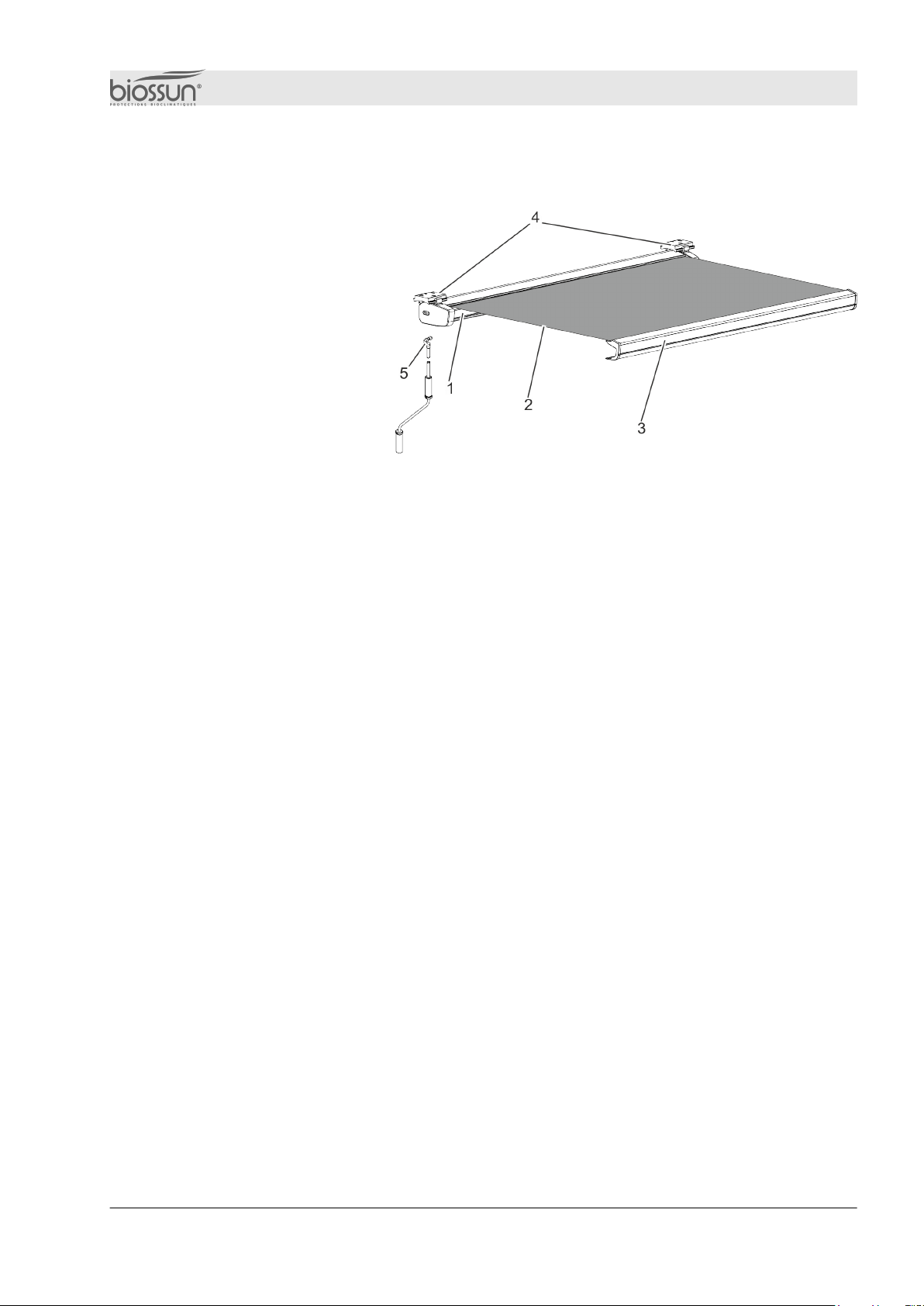
1 Folding arm awning BIO K
Fig. 1: Awning K
1 Cassette
2Awning
3Drop bar
4 Consoles
5Handwheel (control option)
Motor (ordering option)
The cassette (Fig. 1/1) is attached to the support surface by the
brackets (Fig. 1/4). The drop bar (Fig. 1/3) is connected to the
articulated arms (under the awning) and to the awning (Fig. 1/2).
The electric drive can be operated either by permanent wiring with
directional buttons, by a control knob, by radio remote control or by
automatic control.
Manual operation is by crank.
Folding arm awning BIO K
02.09.2021 Folding arm awning BIO K 5
Safety instructions in these instructions are indicated by symbols.
Safety instructions begin with signal words indicating the extent of
the hazard.
WARNING!
This combination of symbol and signal word
indicates an imminently hazardous situation
which, if not avoided, will result in death or
serious injury.
WARNING!
This combination of symbol and signal word
indicates a potentially hazardous situation which,
if not avoided, could result in death or serious
injury.
WARNING!
Risk of injury from electric current!
Improper work on the awning's electrical
components can result in serious injury or death.
–Work on electrical components may only be
carried out by qualified electricians.
–The blind may only be connected if the
specifications on the nameplate match the supply
voltage.
–Follow the supplied motor operating instructions.
WARNING!
Risk of crushing from moving parts!
Moving awning parts present a crushing hazard.
- Secure support arms and end rail during assembly
2 Security
Safety notes
Electric current
(with electric drive)
Moving parts
Security
02.09.2021Folding arm awning BIO K6

WARNING !
Risk of injury from falling from height!
Working at height and using climbing equipment
present a risk of injury from falls.
–Use appropriate safety equipment.
–Never fix or support climbing aids on the
awning.
–Climbing aids must be sturdy and offer
sufficient handholds.
–Never hang on to the awning.
WARNING !
Danger when lifting the awning with ropes!
If the awning has to be lifted using ropes, there is a risk
of fatal injury due to crushing.
–Secure the ropes to the awning.
–Make sure that the awning cannot come loose from
the ropes.
–Keep the awning horizontal when lifting.
–Do not enter the danger zone beneath the load.
Working at height
Lifting with ropes
Security
02.09.2021 Folding arm awning BIO K 7

WARNING!
Risk of injury from incorrect disassembly/
reassembly!
Incorrect disassembly/reassembly increases
the risk of injury from moving parts or working
at height.
–Disassembly/reassembly should only be carried out
by a qualified installer.
–If you plan to reassemble the blind, make sure you
have all the documentation.
–Ask Biossun for any missing documents.
–Make sure you have enough space before you start
work.
–Handle exposed and sharp components with care.
–Keep your workspace tidy and clean! Stacked or
scattered components and tools present an accident
hazard.
–Dismantle the components as required. Note that
some of the components are heavy. If necessary,
use a lifting device.
–Secure components to prevent them from falling or
tipping over.
–In doubt, consult Biossun
WARNING
Risk of material damage when folding out
the awning!!
Extending the awning can cause it to fall or be
damaged.
–Do not test in freezing or snowy conditions.
–Remove dead leaves and other foreign
objects from the awning.
–Remove any obstacles.
Hearing protection
Hearing protection is used to protect hearing from noise
damage.
Dismantling old systems
Awning extension
Personal protective equipment
Security
02.09.2021Folding arm awning BIO K8
Safety helmet
Safety helmets protect the head from falling objects, swinging
loads and impacts with fixed objects..
Safety goggles
Goggles are used to protect eyes from flying debris and liquid
splashes.
Safety shoes
Safety shoes protect feet from falling parts, and prevent crushed
feet or slipping on slippery floors.
Qualified installer
A qualified installer has the technical skills, experience and
knowledge of applicable standards and regulations required to
carry out work on awnings and to recognize and avoid potential
hazards. A qualified fitter has training and experience in the
following areas:
nOccupational health and safety, industrial safety and accident
prevention regulations
nHandling ladders and scaffolding
nHandling and transport of long, heavy components
nTool and machine handling
nFastener installation
nBuilding structure assessment
nCommissioning and use of the product
Permanent electrical wiring may only be installed by an officially qualified
electrician.
Qualified persons
Security
02.09.2021 Folding arm awning BIO K 9
3 Preparing the assembly
Assembly requires at least two people.
Protective equipment :
Staff: nQualified personnel
nHearing protection
nIndustrial helmet
nSafety shoes
nSafety goggles
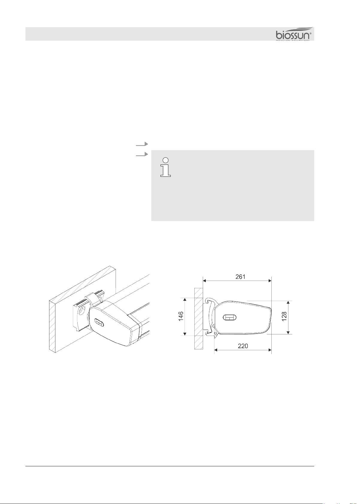
1. Check load-bearing capacity of support surface 2.
Suitable fastening materials
–For outdoor installation, use stainless steel
bolts.
–In the vicinity of swimming pools, use
galvanized steel bolts to counter the risk of
corrosion due to the presence of chlorine in
the air.
–To avoid contact corrosion, do not use steel
and stainless steel parts together.
Keep appropriate fastening materials (not
included) on hand.
Fig. 2: Bracket for wall mounting
Preparing for installation
Wall mounting
Preparing the assembly
02.09.2021Folding arm awning BIO K10

The 90° rotated wall bracket matches the ceiling
bracket
Fig. 3: Bracket for ceiling mounting
Fig. 4: Bracket for rafter mounting
Ceiling mounting
Assembly preparation
02.09.2021 Folding arm awning BIO K 11
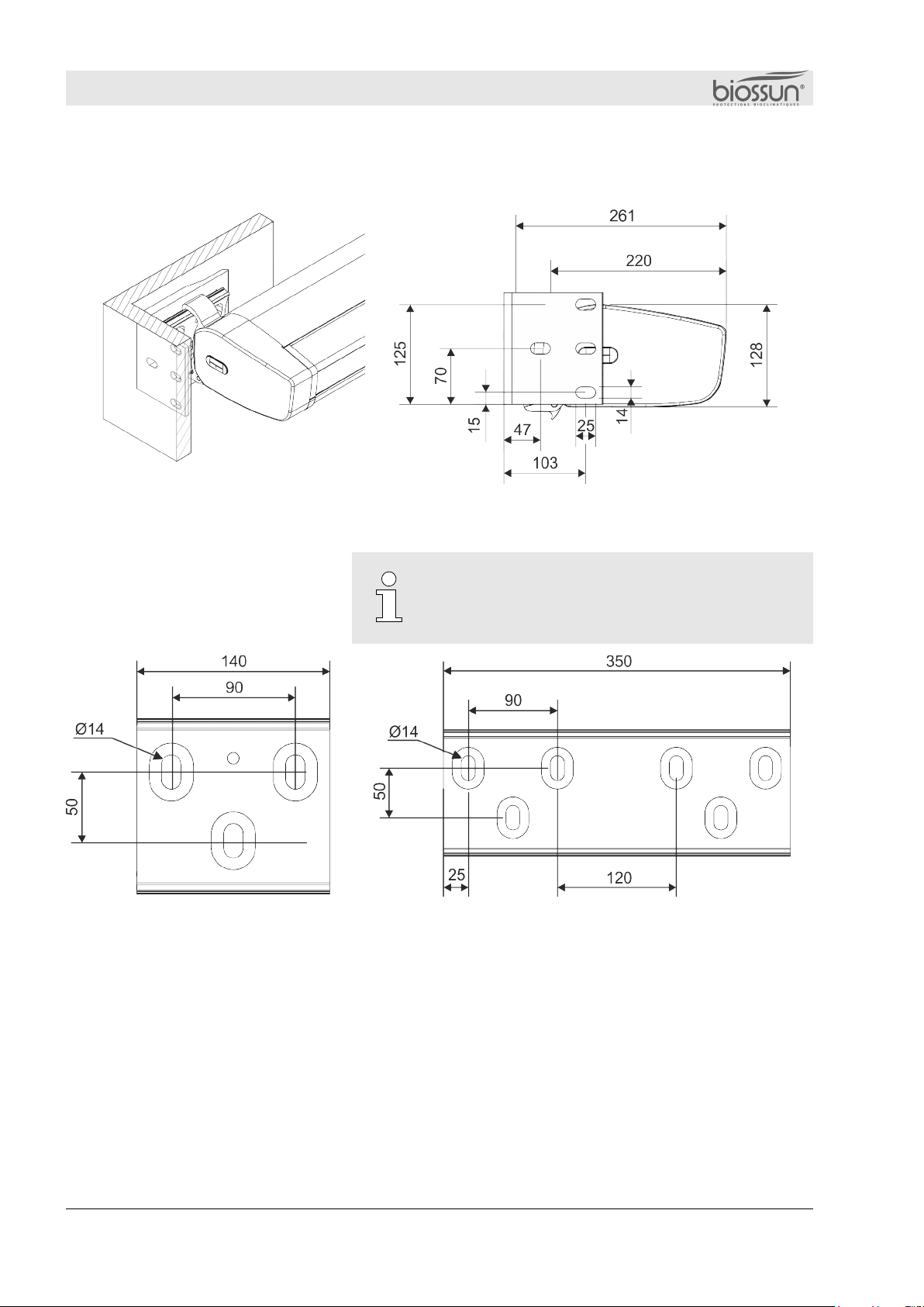
Fig. 5: Bracket for frame mounting
The brackets for wall and ceiling mounting can
also be used as drilling templates.
Fig. 7: Drilling template for wall bracket extension
Frame assembly
Drilling jigs
Fig. 6: Drilling template for
wall/ceiling bracket
Assembly preparation
02.09.2021Folding arm awning BIO K12

Fig. 8:Console extension for wall or ceiling mounting
Fig. 9: Rafter extension
Console extension for wall or
ceiling mounting
Rafter extension
Assembly preparation
02.09.2021 Folding arm awning BIO K 13

Staff:
Protective equipment:
nQualified installer
nHearing protection
nSafety helmet
nSafety shoes
nSafety goggles
1. Determine console mounting height
Positioning
The projection area of the awning must be
free of any rigid or mobile obstacle. The
minimum distance (Fig. 10/X) between the
end rail and a rigid or mobile object must be
at least 40 cm. The minimum height (Fig.
10/Y) between the end rail and the ground
must be at least 180 cm. If these
specifications cannot be met, appropriate
safety measures must be applied to the
building (e.g. fencing).
2. Align brackets horizontally.
Use a spirit level or string to align the
mounting holes horizontally.
3. Transfer the drilling diagram (Fig. 12).
4 Mounting the awning
Mounting the brackets
Fig. 10: Blind deployment zone
Fig. 11: Aligning brackets
Fig. 12: Console markings
Mounting the awning
02.09.2021Folding arm awning BIO K14
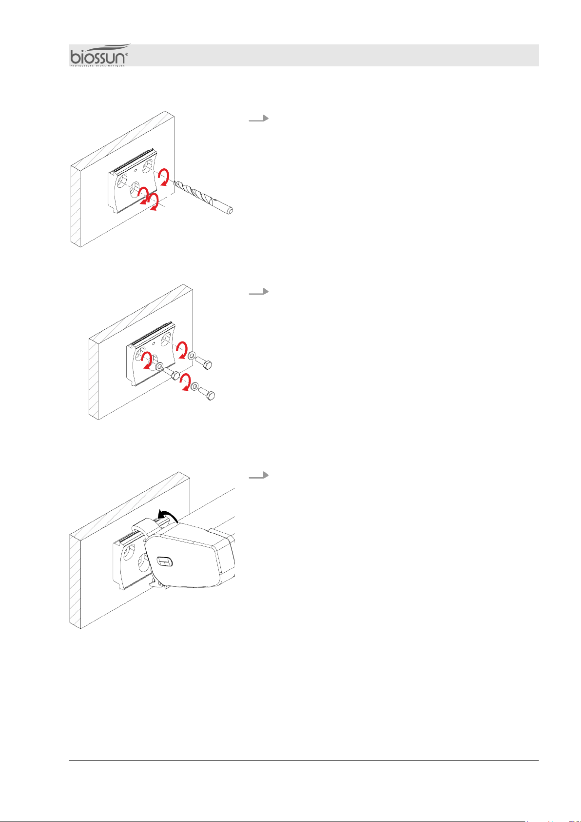
4. Drill the console mounting holes and insert wall plugs if necessary.
(Fig. 13).
5. Screw the brackets to the support surface (Fig. 14).
1. Connect awning to brackets (Fig.15)
Fig. 13: Console drilling
Fig. 14: Screwing the console
Awning connection
Fig. 15: Awning connection
Mounting the awning
02.09.2021 Folding arm awning BIO K 15
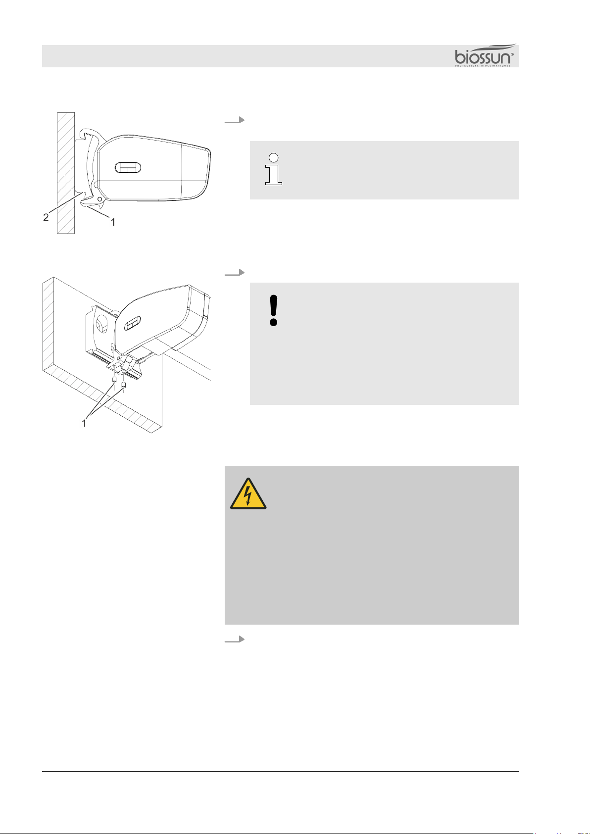
2. Use the ratchet levers (Fig. 16/1) to lock the awning securely in the locking lugs
Fig. 16/2).
The ratchet lever is permanently tensioned
by a spring. When it engages the locking
lugs, a click is heard.
3. Secure the awning with the clamping screws (Fig. 17/1).
WARNING!
Material damage and injury if awning is
not secured!
Si l'auvent glisse hors des consoles, cela
peut entraîner des dégâts matériels
importants et des blessures.
– Always secure the awning with the
clamping bolt
WARNING!
Risk of injury from electric current!
Improper work on the awning's electrical
components can result in serious injury or death.
–Work on electrical components may only be
carried out by qualified electricians.
–The blind may only be connected if the
specifications on the nameplate match the supply
voltage.
–Follow the supplied motor operating instructions.
Connect the drive to the power supply as described in
the enclosed motor manual.
Fig. 16: Fixing the awning
Fig. 17: Mounting the awning
Device connection
Mounting the awning
02.09.2021Folding arm awning BIO K16

WARNING!
Risk of damage to the fall bar and
malfunction of the awning!
–Make sure the drop bar is horizontal.
–The angle of inclination of the individual
folding arms must not differ by more than
10°.
Tilt angle can be set from 0 to 40°.
To change the shaded area and orient the awning, adjust
the angle of inclination.
1. Extend the awning by 50 to 80 cm.
2. Take the strain off the blind by gently lifting it while
adjusting the angle of inclination.
Fig. 19: Angle adjustment
3. Adjust the angle of inclination of all folding arms using the
adjusting screw with hexagon socket SW10 (Fig. 19/1).
Counter-clockwise : The angle of inclination increases - the
folding arm lowers.
nClockwise : The angle of inclination is reduced - the
folding arm is raised.
4. Check that the blind is horizontal.
5 Awning adjustment
Tilt angle adjustment
Fig. 18: Tilt angle adjustment
Awning adjustment
02.09.2021 Folding arm awning BIO K 17

Fig. 20: Arm level adjustment
To ensure that the folding arms move freely and avoid contact with the
canopy, the level of the arms must be adjusted.
1. Extend the awning by 50 to 80 cm.
2. Ease the awning by gently lifting it while adjusting the
arm level.
Fig. 21: Arm level adjustment components
3. Loosen the M6x10 hex head clamping screw
(Fig. 21/1) on the upper arm fork (Fig. 21/3).
4. Bring the folding arms into a horizontal position using a 5
mm wrench on the folding arm eccentric bearing screw (Fig.
21/4) (Fig. 21/2).
Arm level adjustment
Blind adjustment
02.09.2021Folding arm awning BIO K18
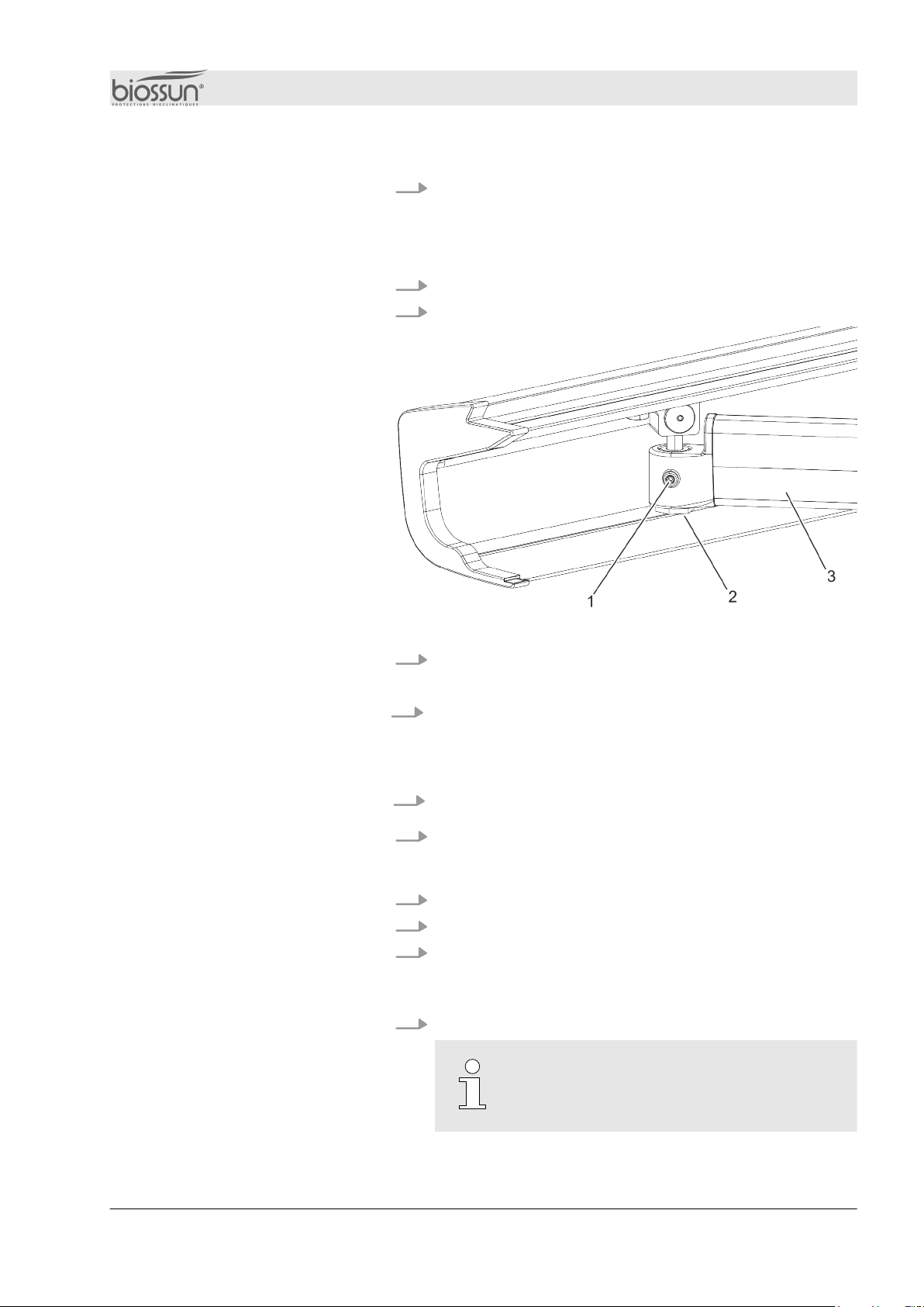
5. Tighten the M6x10 hex head clamping bolt
(Fig. 21/1).
1. Unfold the blind by approx. 70 cm.
2.
Fig. 22: End rail adjustment
3. Unscrew the M5x10 threaded pin from the clamping screw
(Fig. 22/1).
4. Use the size 22 drop bar attachment (Fig. 22/2) on the arm
profile (Fig. 22/3) to adjust the drop bar.
nCounter-clockwise : The drop bar lifts.
nClockwise : The drop bar lowers.
5. Tighten the M5x10 threaded pin of the clamping screw
(Fig. 22/1).
6. Check that the end rail is horizontal.
1. Fully extend the awning
2. Retract the blind by about 1 cm.
3. Fix the position of the bottom end of the motor as indicated
in the motor manual.
1. Retract the blind.
The motor stops in the upper end position
due to the increased torque.
Load bar adjustment
End position adjustment
(with electric drive)
Lower end position
Upper end position
Blind adjustment
02.09.2021 Folding arm awning BIO K 19

2. Check cassette alignment and closure. If the cassette
does not close properly :
n
Ä
"Arm level adjustment" on page 18
n
Ä
"Adjusting the drop bar" on page 19
1. Fully extend the awning. Make sure the engine is
switched off.
Retract blind
2. Make sure the blind rolls up evenly.
nMake sure the cassette closes properly. If the
cassette does not close properly :
n
Ä
"Arm level adjustment" on page 1
n
Ä
"Adjusting the drop bar" on page 19
Function control
Blind adjustment
02.09.2021Folding arm awning BIO K20
Table of contents
Popular Lawn And Garden Equipment manuals by other brands


FLORABEST
FLORABEST FGS 10 A1 translation of original operation manual

Goodlife
Goodlife Guardian instruction manual

LuxenHome
LuxenHome WHPL1274 instruction manual

Tube-Line
Tube-Line BF 5000SL manual

FLORABEST
FLORABEST FLV 1200 A1 translation of original operation manual

In 2 Care
In 2 Care Mosquito Station Quick installation guide