biossun BIO230 NVS User manual

Installation instructions
Pergola BIO230 NVS

2
Pergola BIO230 NVS
Table des matières
1. Directives ........................................................................................................................................................................... 3
2. Overview ............................................................................................................................................................................ 4
2.1. 3D overview ............................................................................................................................................................. 4
2.2. Tools overview ......................................................................................................................................................... 4
2.3. Fixing options: .......................................................................................................................................................... 5
3. Safety ................................................................................................................................................................................. 6
4. Preparing assembly ......................................................................................................................................................... 11
4.1. Checking the basic elements delivered .................................................................................................................. 11
4.2. Checking the power supply characteristics ............................................................................................................ 14
4.3. Checking the fixing supports (walls and floor) ....................................................................................................... 15
4.4. Choice of fixing materials ....................................................................................................................................... 16
5. Mounting the pergola ...................................................................................................................................................... 17
5.1. Place the beams on trestles ................................................................................................................................... 17
5.2. Connect the various cables and extensions ........................................................................................................... 17
5.3. Assemble the corners and seal them ..................................................................................................................... 18
5.4. Mount the top PDLs ............................................................................................................................................... 20
5.5. In case of wall mounting, drill holes in the frame(s) intended to be set against the wall(s) ................................. 21
5.6. Set in place the EP with a layer of sealing .............................................................................................................. 23
5.7. Seal every junction ................................................................................................................................................. 24
5.8. Reassemble the wheel of the motor(s) and install the motor cover ..................................................................... 25
5.9. Install the motion rod and link it with the motor(s) .............................................................................................. 27
5.10. Install a slat at each end and next to each motor ............................................................................................. 29
5.11. Cut the posts to size (if necessary, and move the bottom PDLs inside the posts) ............................................ 31
5.12. Raise the pergola above its installation height ................................................................................................. 32
5.13. Set the posts in place on the ground ................................................................................................................ 33
5.14. Lower the pergola on its posts .......................................................................................................................... 34
5.15. In case of wall mounting, set the pergola next to the intended wall, drill the wall and tighten the fixation ... 35
5.16. Check that the posts are vertical and that the diagonals are equal .................................................................. 37
5.17. Lock upper PDLs in place ................................................................................................................................... 37
5.18. Fix the posts to the ground ............................................................................................................................... 38
5.19. Lock bottom PDLs in place ................................................................................................................................ 41
5.20. Pipe the EP post (if necessary) .......................................................................................................................... 41
5.21. Put the slats in place ......................................................................................................................................... 42
5.22. Fit the cover of the opposite motor position rod ............................................................................................. 43
5.23. Set up the electronics in the technical post ...................................................................................................... 44
5.24. Fit the posts cover ............................................................................................................................................. 46
6. Troubleshooting .............................................................................................................................................................. 47
7. Technical data .................................................................................................................................................................. 48
8. Index ................................................................................................................................................................................ 49

3
Pergola BIO230 NVS
1. Directives
About these instructions
These instructions contain important information on correct and
safe assembly of the pergola. Make sure to read them in their
entirety before installing the product. Failure to do so may
otherwise result in hazards to persons or damage to the product.
When passing on the pergola to a third party, make sure that theses
instructions are also included.
Illustrations in these instructions are intended to convey a general
understanding and may differ from the actual design.
Limitation of liability
The manufacturer cannot accept any liability in the following cases:
§ Failure to observe theses instructions.
§ Execution of work and repairs by non-qualified persons.
§ Technical modifications.
Support
Address Biossun SAS
24 rue de la Sure
38360 Sassenage
FRANCE
Phone +33 (0)4.80.42.08.10
e-mail info@biossun.com
Other applicable documents
§ User manual for pergola
§ If included in scope of supply: Instruction manual for radio
remote control
4
Pergola BIO230 NVS
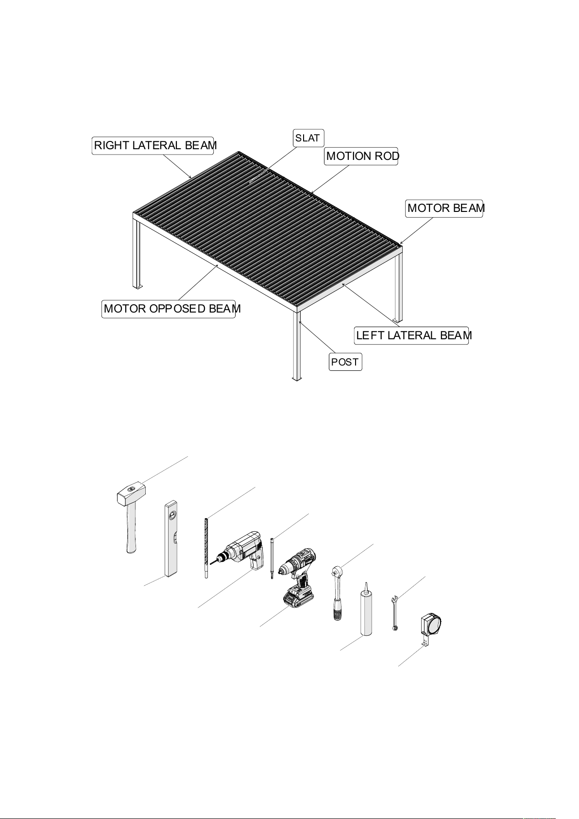
2. Overview
2.1. 3D overview
2.2. Tools overview
RIGHT LATERAL BEAM
MOTOR BEAM
SLAT
MOTION ROD
MOTOR OPPOSED BEAM
LE FT LATERAL BEA M
POST
Spirit level
Sledgehammer
Drill
Concrete dr ill
Screwer
Screwer extension
Silicone
Dynamometric wrench
Open-end spanner
Tape measure

5
Pergola BIO230 NVS
2.3. Fixing options:
o Standard (directly to the ground)
o Wide plate
>105. 00 mm >105. 00 mm
<105. 00 mm <105. 00 mm

6
Pergola BIO230 NVS
3. Safety
Safety note design Safety notes in these instructions are indicated by symbols.
The safety notes begin with signal words that indicate the
magnitude of the hazard.
Tips and recommendations
Safety instructions in specific Safety instructions may refer to specific, individual instruction
instructions Such safety instructions are integrated into the instruction so
that they do not interrupt the flow of reading when carrying
out the task.
The signal words described above are used.
Example:
1. Loosen the screw.
2.
Close the cover carefully.
3. Tighten the screw.
DANGER !
This combination of symbol and signal word indicates
an imminently hazardous situation that will result in
death or serious injury if it is not avoided.
WARNING!
This combination of symbol and signal word indicates
a potentially hazardous situation that can result in
death or serious injury if it is not avoided.
NOTICE!
This combination of symbol and signal word indicates a
potentially hazardous situation that can result in
property damage if it is not avoided.
This symbol highlights useful tips and recommendations
as well as information designed to ensure efficient and
smooth operation.
CAUTION!
Risk of pinching by cover!

7
Pergola BIO230 NVS
Additional symbols The following symbols are used in this manual to highlight
instructions, results, lists, references and other elements:
Symbol Explanation
Step-for-step instructions
Results of instruction steps
References to sections in this manual and to
other applicable documents
Lists without a specified sequence.
Risk of injury due to electrical
current
Electrical current (with electric
drive)
DANGER!
Risk of injury due to electrical current!
The lighting is powered by electric current. Work
performed improperly on the lighting can result in serious
or fatal injury.
- Electrical installations or repairs may only be carried
out by electricians.
- Do not allow any fluids to enter the lighting.
- Do not use flammable cleaning agents.
WARNING!
Risk of injury due to electrical current!
Work performed improperly on the awning’s electrical
components can result in serious or fatal injury.
- Work on the electrical components must be
performed by qualified electricians only.
- The pergola may only be connected if the
specifications on the type plate match the power
supply voltage.
- Observe the enclosed motor operating manual.
8
Pergola BIO230 NVS
Risk of burning
Risk of damage to eyes
Danger of falling
Lifting
WARNING !
Risk of burning during operation of the
lighting!
If the lamps are touched during operation, there is
an acute risk of burning.
- Do not touch lamps when they are in operation.
- Let lamps cool down before touching theme.
WARNING!
Risk of damage to eyes due to direct eye
contact with the lamp
Longer eye contact with a switched-on lamp
can damage the eyes.
- Avoid direct eye contact with the lamp.
WARNING!
Risk of injury due to falling from heights!
Working at heights and on climbing aids poses a risk of
injury due to falling.
- Use suitable safety gear.
- Never fasten or lean climbing aids on the pergola.
- Make sure that climbing aids are standing firmly
and provide sufficient support.
- Never hold on to the pergola.
WARNING!
Hazard posed by lifting the awning!
When lifting the pergola, e.g. using ropes, there is a risk
of fatal injury through crushing.
- Securely attach the ropes to the awning.
- Make sure that the pergola cannot slip free of the
ropes.
- Keep the pergola horizontal when lifting it.
- Do not enter the danger zone beneath the load.
9
Pergola BIO230 NVS
Disassembling or reassembling old
systems
Operating the slats
WARNING!
Risk of injury due to improper disassembly or
reassembly!
Improper disassembly or reassembly poses an increased
risk of injury due to moving parts or working at height.
- Have disassembly/reassembly be performed only by
a qualified fitter.
- If reassembly is planned, make sure that all of the
pergola’s documentation is available. Request any
missing documents from Biossun SAS.
- Make sure sufficient space is available before
beginning work.
- Handle exposed, sharp-edged components with
care.
- Keep the workspace tidy and clean! Loosely stacked
or scattered components and tools pose a risk of
accident.
- Disassemble components properly. Note that some
of the components are heavy. If necessary, use
lifting gear.
- Secure components to prevent them from falling or
toppling over.
- Consult Biossun SAS in any cases of doubt.
NOTICE!
Risk of property damage when extending the awning!
When rotating the slats, there is a risk of damaging them if
they collide with obstacles.
- Remove fallen leaves and other foreign objects
from the pergola.
- Do not operate the pergola in freezing weather
or when it is snowing.
- Remove any obstacles.
10
Pergola BIO230 NVS
Qualified persons
Qualified fitter
A qualified fitter has the technical skills and experience as well as knowledge
of the applicable standards and regulations required to perform work on
shading systems and to recognise and avoid potential hazards.
The qualification includes:
§ Knowledge of health and safety, industrial safety and
accident prevention regulations
§ Assessment of building fabric
§ Safe handling of ladders and scaffolds
§ Safe handling and transport of long, heavy components
§ Safe handling of tools and machines
§ Correct installation of attachment elements
§ Commissioning and operating the product.
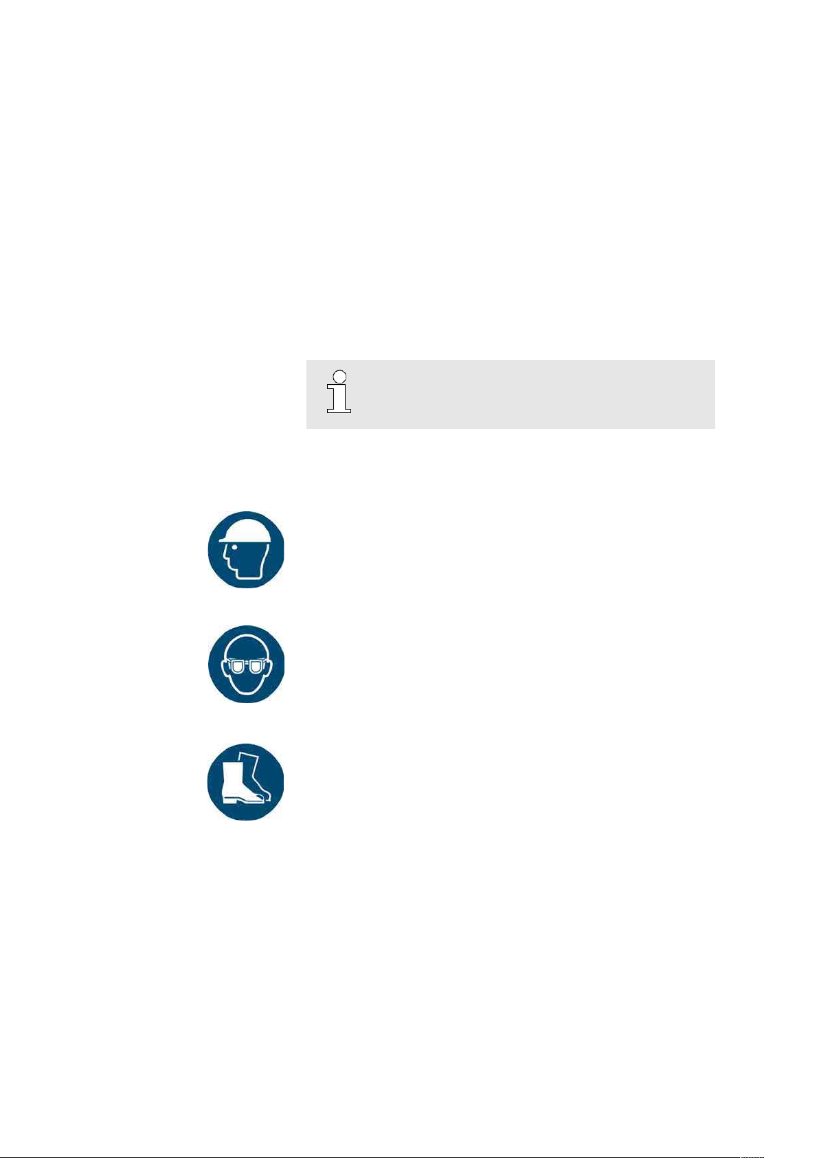
Personal protective equipment
Industrial helmet
Industrial helmets protect the head against falling objects, swinging loads
and impacts with fixed objects.
Safety goggles
Safety goggles protect your eyes from flying parts and spraying liquids.
Safety shoes
Safety shoes protect the feet from crushing, from dropping parts,
and from slipping on slippery floors.
The permanent electrical wiring must be installed by an
officially qualified electrician only.

11
Pergola BIO230 NVS
4. Preparing assembly
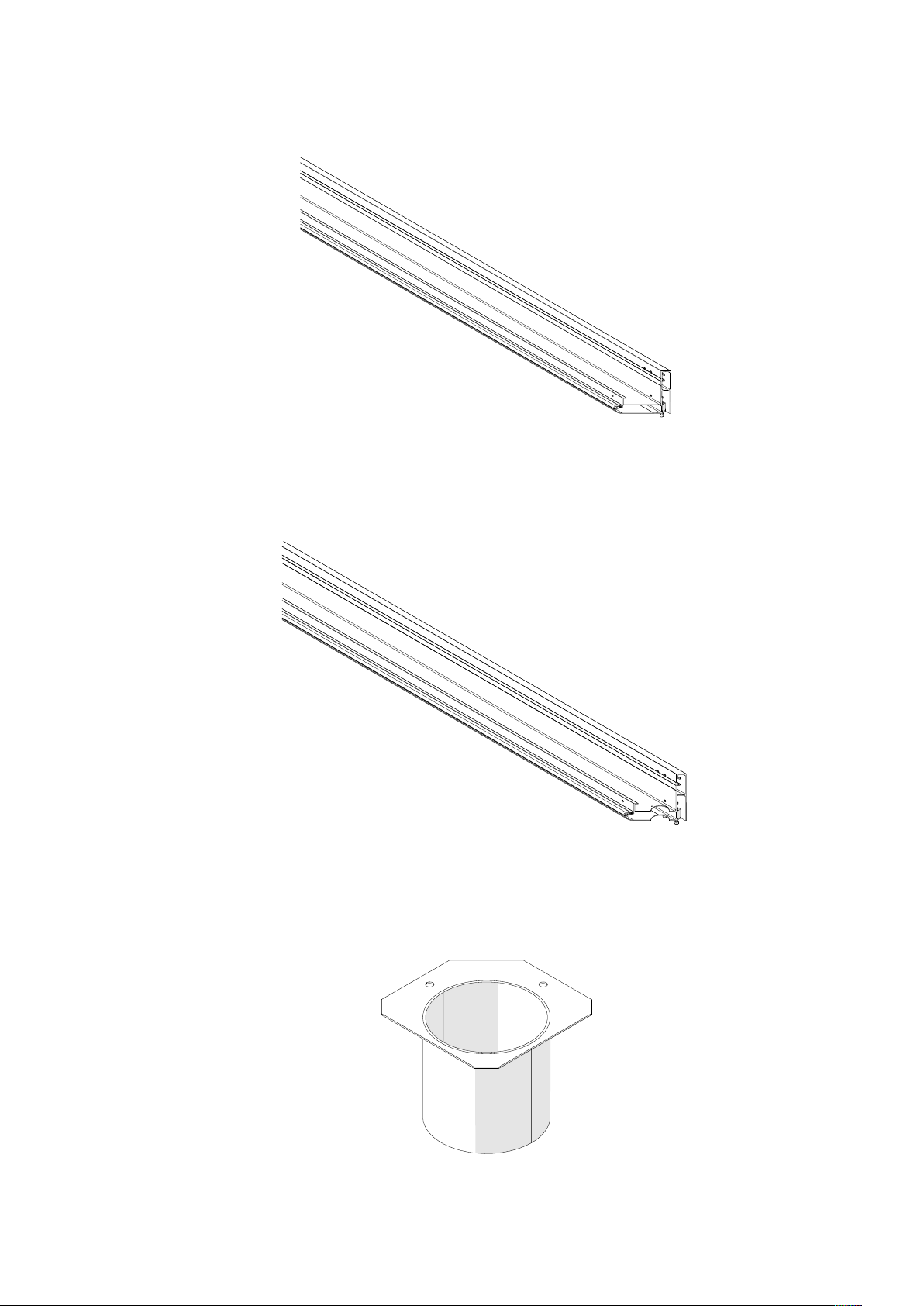
4.1. Checking the basic elements delivered
- Motor beam
- Motor opposed beam
- Position rod cover
12
Pergola BIO230 NVS
- Right lateral beam
- Left lateral beam
- EP
13
Pergola BIO230 NVS
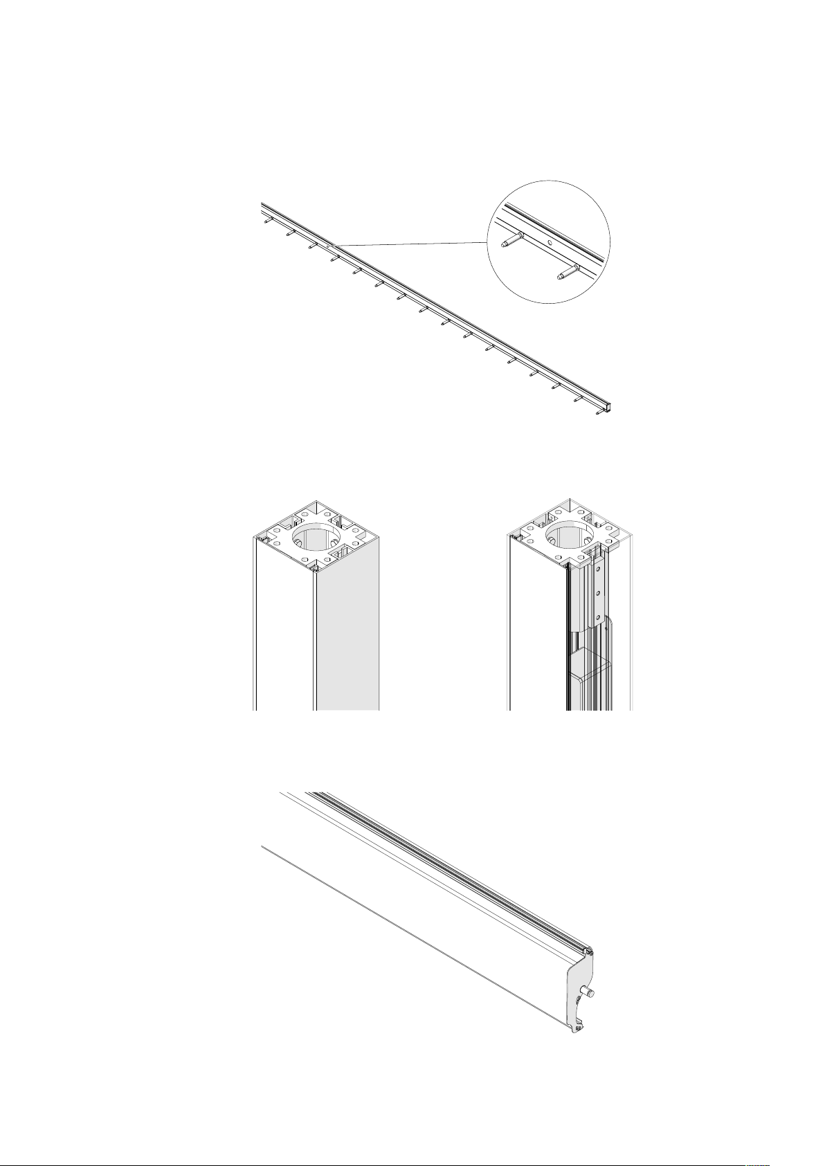
- Motion rod
- Posts/Technical post
- Slats
14
Pergola BIO230 NVS
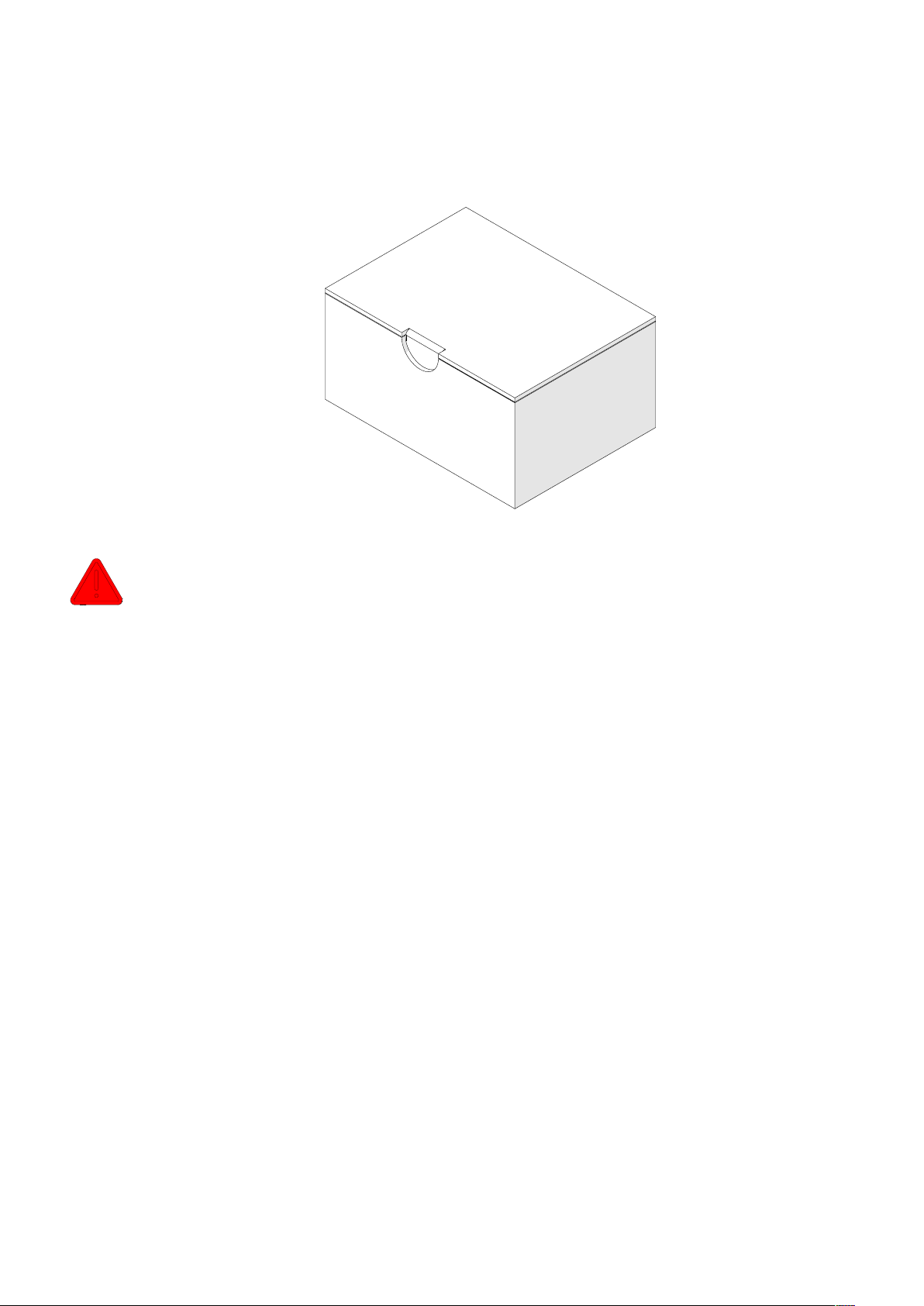
- Screws (all the screws you need to assemble the pergola are provided)
- Be advised: all the components used to anchor the pergola to the ground or to a wall are
NOT provided,
- Before installing, make sure the machinings on your components matches what you ordered,
4.2. Checking the power supply characteristics
Make sure your power supply has the following characteristics:
- Voltage: 230 V,
- Frequency: 50 Hz,
Electric protection:
- 10 A protection with a 30mA differential,
Power cable:
- Three-wires cable with grounding (min. Ø1.5 mm2)

15
Pergola BIO230 NVS
4.3. Checking the fixing supports (walls and floor)
- We recommend installing the pergola on an at least grade C25/30 concrete slab respecting
the following configuration:
- In case of wall mounting you may face two situations:
140,00 mm
M12
70,00 mm
50,00 mm
90,00 mm
70,00 mm
90,00 mm
Installation against a concrete wall
Concrete anchor specification
Type
M12 x 120
Shear strength
17 kN
Tensile strength
9 kN
Concrete anchor specification
Type
M12 x 120
Shear strength
17 kN
Tensile strength
9 kN

16
Pergola BIO230 NVS
- Before you start installing our product, make sure you have a clearance of at least 100mm
above the top of the pergola:
4.4. Choice of fixing materials
Whether you install the pergola on the ground or against a wall, always use stainless steel screws.
70,00 mm
90,00 mm
Installation through an insulation layer
It is highl y recommen ded to use a spacer (not provide d)
clearan ce > 10 0 mm

17
Pergola BIO230 NVS
5. Mounting the pergola
5.1. Place the beams on trestles
5.2. Connect the various cables and extensions
While doing this step, keep in mind that the various cables must end up in the technical post.
Connect matching colors
18
Pergola BIO230 NVS
The rain and wind sensors cables layout must be addressed at this step, before assembling the
corners.
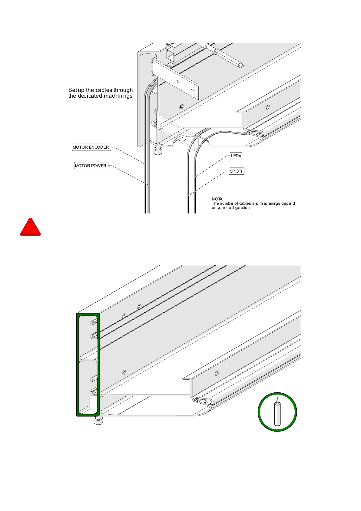
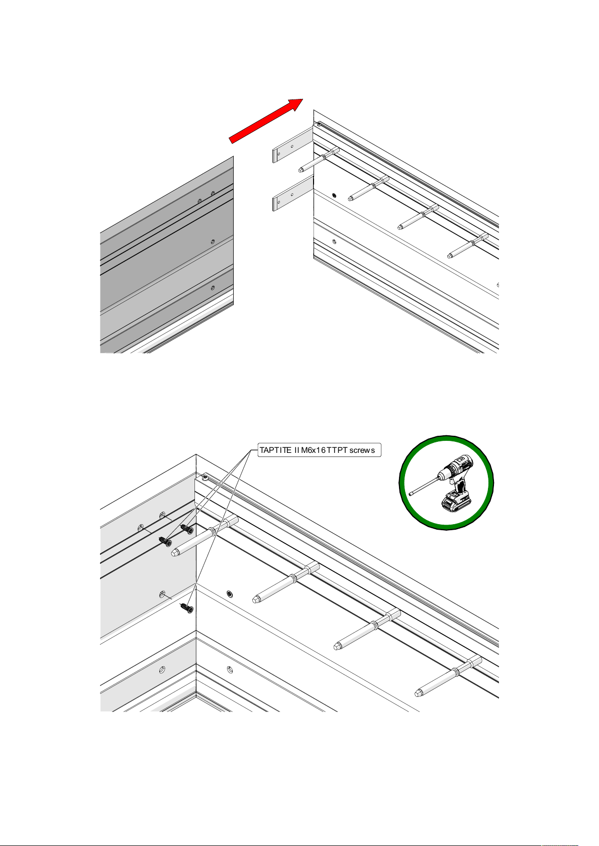
5.3. Assemble the corners and seal them
SP OTs
MOTOR POWER
LEDs
MOTOR EN COD ER
Set up the cables through
the dedicated machinings
NOTA
The number of cables and m ac hinings depend
on your configuration
19
Pergola BIO230 NVS
TAPTITE II M6x16 TTPT screws

20
Pergola BIO230 NVS
5.4. Mount the top PDLs
TAPTITE II M6x16 TTBT screws
WARNING
The way y ou angle t he PDL impact
th e w a y the p o st is a ng le d
Table of contents
Popular Outdoor Furnishing manuals by other brands

BENITO
BENITO Urban Picco PA664S3 Anchoring instructions

Royalcraft
Royalcraft ZURICH ZURGAZ3X3-GREY Assembly and operating instructions

for Living
for Living 399-9879-8 Assembly instructions

Sunjoy Industries
Sunjoy Industries D-GZ822PCO Assembly instructions

Essential Garden
Essential Garden Ridgeway 08402027-0 Use and care guide

vidaXL
vidaXL 44860 manual

Sunjoy
Sunjoy L-GZ660PST-MN Assembly instruction

U-Line
U-Line H-10001 quick start guide

Outdoor GreatRoom Company
Outdoor GreatRoom Company Lodge II Pergola Manual and installation instructions

Gumax
Gumax RAL-7016 Mounting instructions

Anova
Anova F1030R Assembly instructions

Westfield Outdoors
Westfield Outdoors 1318991 instructions


