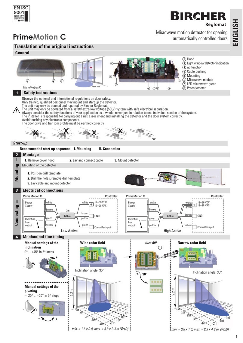
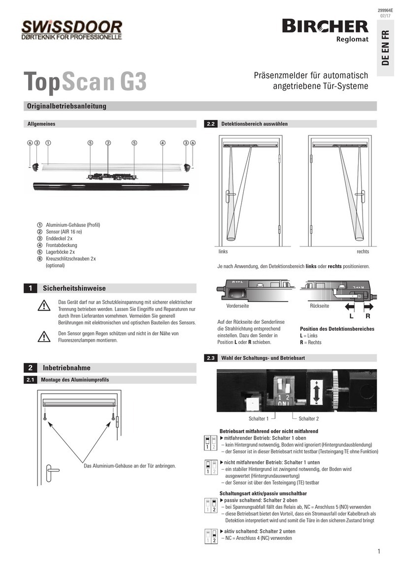
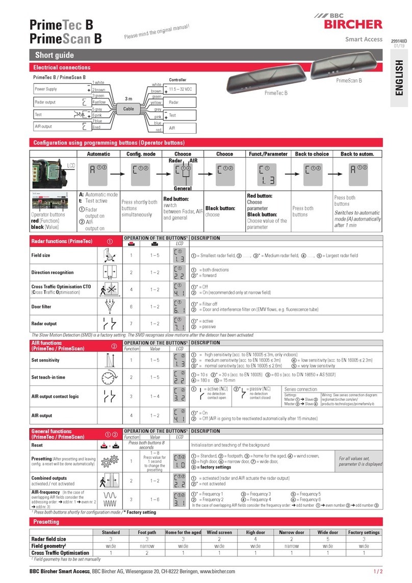
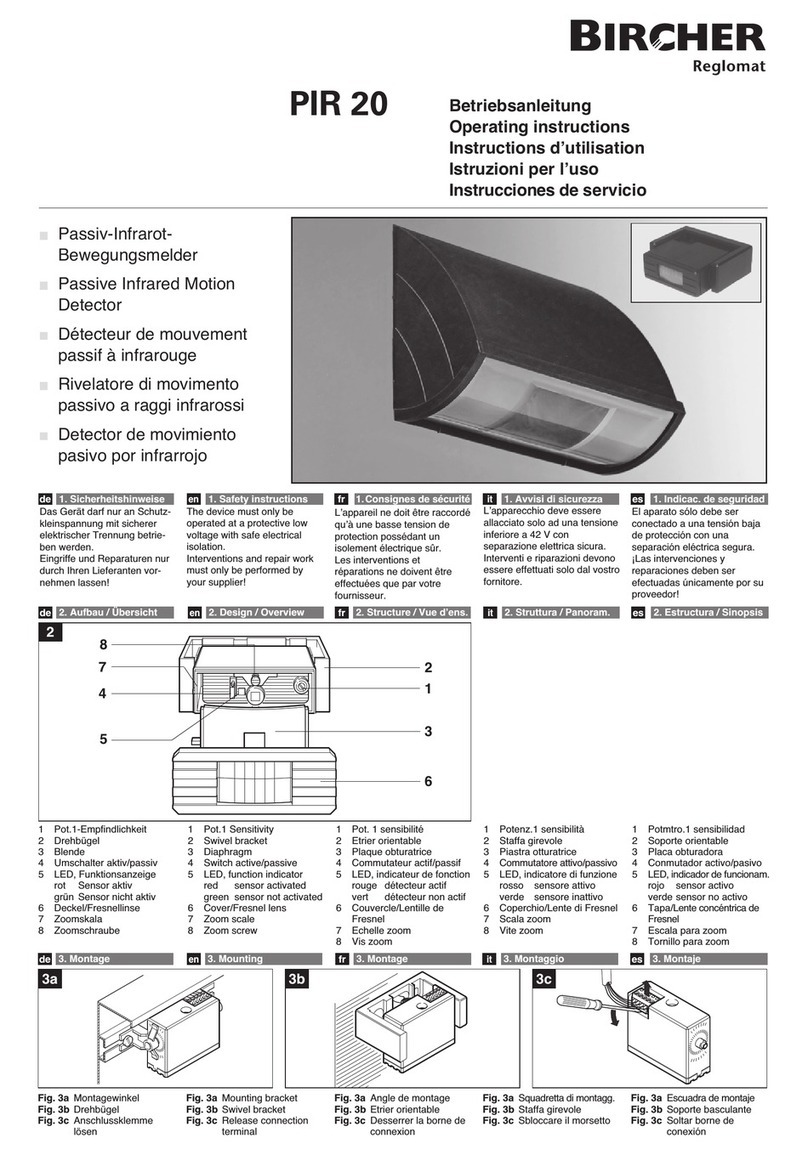
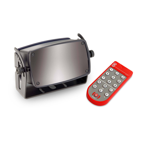
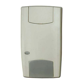
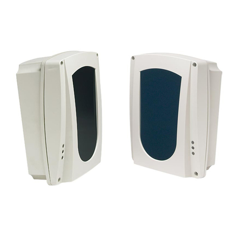
Bircher Merkur 2 ES.SM Series User manual

Merkur 2 ES.SM Radar-Bewegungsmelder als Öffnungs-
impulsgeber für automatische Türen
an Flucht- und Rettungswegen
1
Das Gerät darf nur an Schutzkleinspannung mit sicherer elektrischer
Trennung betrieben werden. Lassen Sie Eingriffe und Reparaturen nur
durch Ihren Lieferanten vornehmen. Vermeiden Sie generell
Berührungen mit elektronischen Bauteilen des Sensors.
LED rot
Aussparungen zur Befestigung
des Sensors
Bodenplatte
Kabeldurchführung
DIP-Schalter (Adressierung)
Taste [<]
Taste [>]
8
9
10
11
14
13
12
Abdeckhaube
Steckschraubklemme
RJ12-Printbuchse
Raster zum Schwenken
des Radarmoduls
Raster zum Neigen
des Radarmoduls
Radar Doppelfeldmodul
LED grün
7
6
5
4
3
2
1
Original-Betriebsanleitung
3.2 Gehäuse öffnen
- Der Sensor muss auf einer ebenen Fläche montiert werden
(Vibrationen vermeiden)
- Der Sensor muss vor Regen und Schnee geschützt sein
- Objekte (z.B. Pflanzen, Fahnen, Ventilatoren, usw.) dürfen nicht in das
Detektionsfeld hineinragen
- Der Sensor darf nicht durch Abdeckungen/Schilder verdeckt sein
- FL-Röhren in unmittelbarer Nähe des Detektionsfeldes müssen vermieden werden
3Installation
3.1 Einbauhinweise
2
3.3 Montage
Bohrschablone an Wand/Decke kleben und Löcher gemäss Angaben bohren
Kabel durch vorgesehene Öffnung der Bodenplatte führen –
auf ausreichende Länge achten für Verdrahtung
Sensor festschrauben
Kabel anschliessen (gemäss Typenschild bzw. Kap. 3.4)
Abdeckhaube auf Bodenplatte klicken
5
4
3
2
1
Artikel Anschluss
Merkur 2 ES.SM.R.
Merkur 2 ES.SM.F.
Merkur 2 ES.SM.F
Merkur 2 ES.SM.V.
Merkur 2 ES.SM.V
Relais
Frequenz
Frequenz
Spannung
Spannung
RJ-Stecker
RJ-Stecker
Steckschraubklemme
RJ-Stecker
Steckschraubklemme
2Beschreibung des Sensors
1
6
12
2
3
14
8
7
5
9
11
10
VOR der Montage NA H der Montage
9
13
4
Merkur 2 ES.SM ist standardmässig richtungserkennend. Zudem ist der Sensor
selbstüberwachend und baumustergeprüft nach DIN 18650.
Signalausgang
1
2
3
4
5
DEUTSCH
222586Q
03/14
Sicherheitsinshinweise

5Konfiguration des Sensors
5.1 Konfiguration mittels Tasten
Stufe
1, 2, 3 klein
4, 5, 6* mittel
7, 8, 9 gross
1* vorwärts, Montagehöhe standard
2 vorwärts, Montagehöhe hoch
3 rückwärts, Montagehöhe standard
4 rückwärts, Montagehöhe hoch
5 Richtungserkennung AUS, Montagehöhe standard
6 Richtungserkennung AUS, Montagehöhe hoch
Der Sensor kann auf zwei Arten konfiguriert werden:
→mittels Tasten am Sensor (grundlegende Einstellungen), Kap. 5.1
→mittels Fernbedienung (vollständige Einstellungsmöglichkeiten), Kap. 5.2
Allgemeine Vorgehensweise
[>]
[<]
Feldgrösse: [<] und [>] 2 s drücken
Funktionalität: [<] und [>] 4 s drücken
Werkseinstellungen wiederherstellen: [<] und [>] 8 s drücken
1) [<] und [>] für entsprechende Zeit gleichzeitig gedrückt halten, alle 2 s blinkt
die grüne LED einmal
2) Häufigkeit der blinkenden grünen LED (1-9 mal) gibt aktuelle Parameterstufe an
3) Mit [<] bzw. [>] kann die Parameterstufe verringert bzw. erhöht werden
4) [<] und [>] kurz gleichzeitig drücken, um den Programmiermodus zu
verlassen (getätigte Einstellungen werden gespeichert)
4Anzeigen am Sensor
Rote ED = Funktionsanzeige
Grüne ED = Statusanzeige
3.4 Elektrische Anschlüsse
Wichtig:
Alle anderen Kombinationen sind nicht zulässig! Bei Türsteuerungen mit
Frequenz- oder Spannungseingang muss für jeden Merkur 2 ES.SM.F/ Merkur 2
ES.SM.Vein separater Eingang zur Verfügung stehen.
Kombination mehrerer Merkur 2 ES.SM für Flucht- und Rettungswege
Gemäss AutSchR müssen Signalgeber den Fluchtweg ohne bewusste
Anforderung flächendeckend freigeben, d. h. in voller Türbreite an jeder Stelle
bis mindestens 1,50 m vor den Türflügeln. Je nach Türgrösse sind hiefür zwei
Sensoren nötig. Einzige zulässige Möglichkeit ist die Kombination von zwei
Merkur 2 ES.SM.R Ausgängen wie folgt:
* Werkseinstellung
RJ12
Anschlussvariante Modell
weiss
10 – 40 V DC
schwarz
rot
grün
gelb
blau
U ein +
U ein –
nicht angeschlossen
F aus
˜
+ 12–36 V DC
– 12–28 V AC
U aus +
U aus –
+12–36 V DC
– 12–28 V AC
nicht angeschlossen
nicht angeschlossen
weiss
schwarz
rot
grün
gelb
blau
+ 12–36 V DC
– 12–28 V AC
weiss
schwarz
rot
grün
gelb
blau
Merkur 2 ES.SM.F.C Merkur 2 ES.SM.V.CMerkur 2 ES.SM.R.C *
Merkur 2 ES.SM.F Merkur 2 ES.SM.V
Steckschraubklemme
10–40 V DC
U ein +
U ein –
F aus
˜
+ 12–36 V DC
–
Uaus +
Uaus –
+ 12–36 V DC
–12–28 V AC
nicht angeschlossen
1
2
3
4
5
braun
blau
schwarz
weiss
1
2
3
4
5
Nicht verfügbar
braun
blau
schwarz
weiss
PIN 1 und 5 durch Drahtbrücke verbinden
Leuchtet →Objekt detektiert
Dunkel →kein Objekt detektiert
Blinkt →Sicherheitsöffnung
(Selbstüberwachung des Systems)
Leuchtet →SMD aktiv
Dunkel →SMD inaktiv
5.1.1 Veränderbare Parameter
Stufe
1 schmales Feld
2* breites Feld
Feldgeometrie: [<] und [>] 6 s drücken
Stufe
Steuerung mit zwei
Eingängen für
Relaissignal
Merkur 2 ES.SM.R. Merkur 2 ES.SM.R.
Merkur 2 ES.SM.R.C
* Die beiden Relaiskontakte sind galvanisch getrennt. Eine Serien- oder Parallelschaltung der beiden Kontakte ist aus sicherheitstechnischen Aspekten nicht zulässig. Beide
Kontakte müssen getrennt auf der Türsteuerung ausgewertet werden. Der Ausgangszustand ist nur korrekt, falls beide Relaiskontakte denselben Zustand aufweisen. Diese
Relais Ausgangs-Funktion muss von der Tür- oder Torsteuerung den relevanten Normenvorgaben entsprechend periodisch überprüft werden.

arameter Schritt 1 Schritt 2
Feldgrösse
Funktionalität
Feldgeometrie
[<] kurz drücken
[>] kurz drücken
[<] und [>] gleichzeitig kurz drücken
Häufigkeit der blinkenden
grünen LED (1-9 mal) gibt
aktuelle Parameterstufe an
Hinweis:
Erfolgt für 25 s keine Tastenbetätigung, wird der Programmiermodus automa-
tisch verlassen, der Sensor bleibt jedoch im Konfigurationsmodus. Die bis dahin
getätigten Einstellungen werden gespeichert.
Die Statusabfrage dient der Abfrage der eingestellten Parameter.
5.1.2 Statusabfrage mittels Tasten
5.2 Konfiguration mittels Fernbedienung
Änderung der Funktionalität von Stufe 6 auf Stufe 2:
1) [<] und [>] für 4 s gedrückt halten, die grüne LED blinkt einmal nach 2 s,
ein weiteres mal nach 4 s
2) Grüne LED blinkt 6 mal und gibt somit die aktuelle Parameterstufe an
3) Vier mal nacheinander die Taste [<] drücken, um die Parameterstufe
zu verringern (grüne LED blinkt 2 mal und gibt die neu eingestellte
Parameterstufe an)
4) [<] und [>] gleichzeitig drücken
Beispiel
Der Sensor kann mittels eines vierstelligen Zugangscodes (Passwort) gegen unerwünschte Manipulation durch Dritte geschützt werden. Mit diesem ode kann der
Konfigurationsmodus über die Fernbedienung jederzeit aktiviert werden, um Einstellungen am Sensor vorzunehmen. Die Funktion ”Zugangscode” ist über den Tastencode
erreichbar und wird abgeschlossen durch Drücken der Taste .
Werkseitig ist diese Funktion “Zugangscode” ausgeschaltet, d.h. es ist kein ode gespeichert.
5.2.5 Funktion Zugangscode
Jedem Sensor kann eine Adresse (1*, 2, 3 oder 4) zugeteilt werden.
Unterschiedliche Adressen sind dann notwendig, wenn sich mehrere Sensoren
in Reichweite einer Fernbedienung befinden.
Adresse 1*
Adresse 2
Adresse 3
Adresse 4
5.2.4 Adressierung des Sensors
5.2.1 Funktionsweise
Aktivieren: - Automatisch nach Anschluss des Sensors an
Versorgungsspannung oder
- Sensor kurzzeitig von der Versorgungsspannung trennen oder
- Beliebige Taste [<] oder [>] auf dem Sensor drücken oder
- Zugangscode mittels Fernbedienung eingeben (Kap. 5.2.5)
Beenden: - Tastenkombination drücken oder
- Automatisch nach 30 Min.
+
A 3
* Werkseinstellung
Die Datenübertragung zum und vom Sensor wird durch eine IR-Schnittstelle sicher-
gestellt. Die Verbindung zwischen der Fernbedienung und dem Sensor kann nur
aufgebaut werden, wenn sich der Sensor im Konfigurationsmodus befindet.
5.2.2 Konfigurationsmodus
Der Konfigurationsmodus muss aktiviert sein, um den Sensor mittels
Fernbedienung programmieren zu können.
Hinweis:
Erfolgt für 30 s keine Eingabe, wird die Verbindung beendet. Die bis dahin
getätigten Einstellungen werden gespeichert.
- G sowie eine der Tasten 1 bis 4 leuchten: erfolgreicher Verbindungsaufbau
- G blinkt: kein Verbindungsaufbau
→Konfigurationsmodus aktivieren
→Fernbedienung näher und zielgerichteter auf den Sensor halten
→Batterien in Fernbedienung überprüfen
- Keine Tasten leuchten
→Batterien in Fernbedienung überprüfen/austauschen
5.2.3 Verbindungsaufbau
Ohne Adressierung: Mit Adressierung:
1. Starttaste drücken 1. IR-Schnittstelle der
Fernbedienung mit der Hand
abdecken
2. Starttaste drücken →blinkt
3. IR-Schnittstelle freigeben (Hand
wegnehmen)
4. Entsprechende Nummerntaste
( bis ) drücken
G
G G
1 4
Die Verbindung zwischen Fernbedienung und Sensor kann erst nach Aktivierung
des Konfigurationsmodus (s. Kap. 5.2.2) hergestellt werden.
REGLO
beam
G
REGLO
beam
Code
4x
drücken
→leuchten, d. h. die Funktion
“Zugangscode” ist ausgeschaltet
(kein ode gespeichert)
4stelligen ode eingeben (frei wählbar
von 1111 bis 998) Mit bestätigen
→ leuchten, d. h. die Funktion
“Zugangscode” ist eingeschaltet
( ode gespeichert)
Verbindungsaufbau herstellen
(Kap. 5.2.3)
Nummerntasten bis
1 9
IR-Schnittstelle (Infrarot)
Funktionstasten bis
A F
Start
G
REGLO
beam
C
REGLO
beam
C
9
+
Zugangscode einschalten (Code speichern)
Der ode kann nur gespeichert werden, wenn der Sensor bereits im Konfigurationsmodus ist. Direkt nach erstmaligem Abspeichern des odes ist das Gerät geschützt, d. h.
der Konfigurationsmodus ist deaktiviert.
+
C 9 C
+
C 9
+
C 1
+
C 2
C

Parameter
Richtungserkennung
Feldgrösse
Relaishaltezeit
SMD-Funktion
Montagehöhe
Querverkehr
Störunterdrückung
SMD-Feldgrösse
Feldgeometrie
C 1
+ * +
C2 +
C3 +
C4 +
C5 +
C6
Standard
EIN, vorwärts
6
1 s
Aus
Bis 3 m
Gering
Aus
1
Breit
C1
Gehsteig
EIN, vorwärts
7
0.8 s
Aus
Bis 3 m
Mittel
Aus
1
Schmal
C2
Altersheim
AUS
6
2 s
Abfallend, 2 s
Bis 3 m
Aus
Aus
5
Breit
C3
Windfang
EIN, vorwärts
6
0.2 s
Aus
Bis 3 m
Gering
Aus
1
Schmal
C 4
Supermarkt
EIN, vorwärts
9
1.5 s
Abfallend, 2 s
3-4 m
Aus
Aus
5
Breit
C5
Hohe Montage
EIN, vorwärts
9
1 s
Aus
3-4 m
Mittel
Aus
1
Breit
C6
3 m
(9.84')
>
Tastencode
Komfortfunktionen
B
D
+
F 1
+
F 3
+
F 4
+
F 5
+
F 6
+
F 7
+
F 8
Empfehlung: Zuerst Komfortfunktion auswählen, die den Anforderungen am nächsten kommt, danach Parameterstufen entsprechend verändern.
* Werkseinstellung
A1
ca. 15 min.
A2
A3
Manuelle Offenhaltung der Tür wäh-
rend den Einstellarbeiten für 15 Min.
Danach schliesst die Tür, wenn kein
Objekt im Detektionsfeld ist.
Tür schliesst, wenn kein Objekt im
Detektionsfeld, danach Normalbetrieb.
Konfigurationsmodus wird beendet,
Tür schliesst wenn kein Objekt im
Detektionsfeld, danach Normalbetrieb.
Um unnötiges Öffnen und Schliessen der Tür während den Einstellarbeiten zu verhindern, kann sie mit der Funktion manuell offen gehalten bzw. wieder geschlossen werden.
5.2.6 Parameter einstellen / verändern
REGLO
beam
G
REGLO
beam
4x 9
4x
drücken
→ leuchten, d. h. die Funktion
“Zugangscode” ist eingeschaltet
( ode gespeichert)
4 mal drücken Mit bestätigen
→leuchten, d. h. die
Funktion “Zugangscode” ist ausge-
schaltet ( ode gelöscht)
Verbindungsaufbau herstellen
(Kap. 5.2.3)
REGLO
beam
C
REGLO
beam
C
9
+
Zugangscode ausschalten (Code löschen)
Der ode kann nur gelöscht werden, wenn der Sensor bereits im Konfigurationsmodus ist.
REGLO
beam
G
REGLO
beam
Code
4x
drücken
→leuchten, d. h. die Funktion
“Zugangscode” ist eingeschaltet
(→Falls leuchten, ist die
Funktion “Zugangscode” ausgeschaltet)
4stelligen ode eingeben Mit bestätigen
→leuchten, d. h. der
Konfigurationsmodus ist aktiviert und
der Sensor ist bereit zur Programmie-
rung (→Falls leuchten, war
der ode falsch; Neubeginn bei 1)
Verbindungsaufbau herstellen
(Kap. 5.2.3)
REGLO
beam
C
REGLO
beam
C
9
+
Konfigurationsmodus aktivieren mittels Zugangscode
Der Konfigurationsmodus kann nur dann mittels Fernbedienung aktiviert werden, wenn zuvor ein ode gespeichert wurde und die Funktion “Zugangscode” eingeschaltet ist.
Zugangscode ausschalten ohne Fernbedienung
Beide Tasten [<] und [>] für 8 s gleichzeitig gedrückt halten. Achtung: Sämtliche Parameter werden auf die Werkseinstellungen zurückgesetzt!
+
C 9
+
C 2
+
C 1
C
+
C 1
9
+
C 9
+
C 1
+
C 2
+
C 2
C
A

Tasten-
code Parameter Stufe Kurzbeschreibung
Komfortfunktionen 1*- 6 vordefinierte Einstellungen für
Standardanwendungen (siehe Tabelle)
Richtungserkennung 1
2
3*
Aus
Rückwärts
Vorwärts
Montagehöhe 1
2* Hoch (3-4 m)
Standard (bis 3 m)
Feldgeometrie 1
2* Schmales Feld
Breites Feld
Feldgrösse 1 - 3
4 - 6*
7 - 9
Klein
Mittel
Gross
Relaishaltezeit
1
2
3
0.2 s
0.5 s Kurz
0.8 s
4*
5
6
1.0 s
1.5 s Mittel
2.0 s
7
8
9
2.5 s
3.0 s Lang
4.0 s
SMD-Funktion
1*
2
3
4
5
6
7
8
9
Aus
0.5 s
1.0 s Empfindlichkeit abfallend
1.5 s
2.0 s
0.5 s
1.0 s Empfindlichkeit konstant
1.5 s
2.0 s (plus SMD+)
SMD-Feldgrösse 1*- 3
4 - 6
7 - 9
Klein
Mittel
Gross
QVA
(Querverkehrsaus-
blendung)
1
2*- 3
4 - 6
7 - 9
Aus
Gering
Mittel
Hoch
Filter zur
Störunterdrückung
1
2*
Ein Vermeidung eventueller
Fehlauslösungen durch FL-Röhren.
Aus
Angegebene Werte gemessen bei Montagehöhe 2.2 m und Neigungswinkel 35°.
SMD = Slow Motion Detection:
Kleinste (quasi-statische) Bewegungen werden detektiert, sobald der Sensor akti-
viert wurde. Erst wenn während der eingestellten
Überwachungszeit keine Bewegung mehr registriert wird, gibt der Sensor das
entsprechende Signal an die Türsteuerung ab. Die Empfindlichkeit während
dieser Überwachungszeit kann abfallend oder konstant gewählt werden.
3 1 . . . 9
Min. 1.1 x 0.6 m (BxT)
Max.4.7 x 1.7 m (BxT)
* Werkseinstellung
Konfiguration einzelner Parameter
Feldgrösse / Feldgeometrie
D+
F 8
In Abhängigkeit der Feldgeometrie (breites/schmales Feld) kann die Feldgrösse
entsprechend eingestellt werden.
Schmales Feld: Breites Feld:
Min. 0.7 x 0.6 m (BxT)
Max. 2.7 x 1.9 m (BxT)
SMD-Funktion und SMD+
+
F 3
SMD+:
löst bei sehr langsamen Bewegungen eine Aktivierung des Sensors aus. Somit
können auch Objekte < 5 (35° Neigungswinkel) , die mit dem normalen
Detektionsfeld nicht erfasst werden, sicher erkannt werden (Altersheim Einstel-
lung). Um zu langes Offenhalten der Tür zu vermeiden, ist das SMD+ Feld unge-
fähr halb so gross wie das Detektionsfeld.
SMD-Feldgrösse +
F 7
F 5 19
F 5 19
Die SMD-Feldgrössen entsprechen ungefähr denen des Detektionsfeldes, d.h.
Die QVA verhindert eine ungewollte Türöffnung bei Personen, die lediglich an
der Tür vorbeilaufen, nicht jedoch eintreten wollen.
+
D 5
+ + ~
F 7 5
Querverkehrsausblendung QVA +
F5
Optimale Sensoreinstellungen:
- Schmales Feld
- Neigungswinkel 30°-45°
5.2.8 Statusabfrage mittels Fernbedienung
Die Statusabfrage dient der Abfrage der eingestellten Parameter. Hierzu muss
die Verbindung zum Sensor hergestellt und der entsprechende Tastencode ein-
gegeben werden. Dann leuchtet eine Nummertaste auf, welche die jeweilige
Parameterstufe angibt.
cm
s
+
F 4
C
B
D
+
F 8
+
F 1
+
F 3
+
F 7
+
F 5
+
F 6
~
5.2.7 Erläuterung einzelner Parameter
T
B
T
B
Hinweis:
Gemäss Richtlinie (AutSchR) muss die Feldtiefe min. 1.5 m betragen.

min. 5
7Beheben von Störungen
Symptom Mögliche Ursache Behebung
Neigungswinkel des Radarmoduls verändern
- Sensor höher und wenn möglich direkt über Türangel montieren
- QVA-Stufe erhöhen
- Sensor in Richtung Türöffnung schwenken
- Feldgrösse überprüfen
- Hohe Montagehöhe aktivieren
- Störunterdruckungsfilter aktivieren
- Sensor geht automatisch in Normalbetrieb zurück
- Service benachrichtigen
Verweis auf Kapitel
6.1.1
5.2.6
6.1.1
5.2.6
5.2.6
Tür reversiert
Tür reversiert
Späte Detektion bzw.
Nichtdetektion von Personen
Tür öffnet ungewollt
Tür steht ungewollt offen
- Sensor sieht Tür
- Sensor sieht Drehflügeltür
- Feld zu klein
- Zu hohe Montage
- Störquelle beeinflusst Radarfeld (z.B. FL-Röhre)
- Einmalige Störung
- Störung, d. h. rote LED blinkt ständig
6Mechanische Einstellungen des Radarfeldes
6.1.1 Neigen des Radarmoduls 6.1.2 Schwenken des Radarmoduls
8Technische Daten
Technologie
Sendefrequenz
Sendeleistung
Betriebsspannung
Betriebsstrom
Netzfrequenz
Ausgänge (typenabhängig)
Relai Typ
Schaltspannung
Schaltstrom
Schaltleistung
Zustand Ausgang
Frequenz Typ
Speisung der Endstufe
Ausgangsstrom
Puls : Pausenverhältnis
Zustand Ausgang
Spannung Typ
Ausgangsspannung
Ausgangsstrom
Zustand Ausgang
Temperaturbereich
Luftfeuchtigkeit
Montagehöhe
Gehäuse
Gewicht
Schutzart
Min. Detektionsgeschwindigkeit
abellänge
Zulassungen
Ländereignung
Radarbewegungsmelder mit Planarmodultechnik
24.125 GHz
< 20 dBm
12-36 V D / 12-28 V A
ca. 50 mA @ 24 V D , 24°
50 Hz
2 potentialfreie NO
max. 48 VA D
max. 0.5 A A / 1 A D
max. 60 VA / 30 W
Relais angezogen (aktiv): keine Detektion/kein Fehler
Relais abgefallen (inaktiv): Detektion oder Fehler
Rechteck NPN-PNP Gegentaktendstufe (kurzschlussfest)
extern 12-36 V D
max. 50 mA, Restspannung max. 2 V
1:1, Abweichung max. 10 %
Ausgangsfrequenz f = 100 Hz ± 10 Hz: keine Detektion/kein Fehler
Ausgangsfrequenz f = 0 Hz: Detektion oder Fehler
Spannungsquelle als Ausgang zum direkten Anschluss von Optokopplern
<10 VD
10 mA bei 3.2 VD
Ausgangsspannung vorhanden: keine Detektion/kein Fehler
Ausgangsspannung < 3VD oder kein Strom: Detektion oder Fehler
-20° bis + 60°
0 bis 90 % rel., nicht kondensierend
Bis 4 m
Haube: P ; Bodenplatte: ABS
Abmessungen: 176 x 62 x 52 mm (B x H x T)
150 g (ohne Kabel)
Geeignet für Einsatz nach IP 54
5 cm/s (in Radarachse)
< 5 cm/s bei SMD+ (Neigungswinkel 35°)
3 m
E 0682 ! / TÜV baumustergeprüft
EU / EFTA-Staaten
5°
45°
-30°
+30°
5°
45° -30° +30°
+ +
F 6 1
D+ +
F 4 1
* Werkseinstellung
1. Die Gewährleistung und Haftung der Bircher Reglomat AG
richten sich nach dem Kaufvertrag.
2. Die Gewährleistung und Haftung erlischt vorzeitig, wenn der
Kunde oder Dritte das Produkt nicht gemäss der vorliegenden
Betriebsanleitung einsetzen und/oder bedienen, der Kunde
oder Dritte unsachgemässe Änderungen oder Reparaturen
vornehmen, der Kunde oder Dritte, falls ein Mangel
aufgetreten ist, nicht umgehend alle geeigneten
Massnahmen zur Schadensminderung treffen und der Bircher
Reglomat AG Gelegenheit geben, den Mangel zu beheben.
3. Von der Gewährleistung und Haftung ausgeschlossen sind
Schäden, die nicht nachweisbar infolge schlechten
Materials, fehlerhafter Konstruktion oder mangelhafter
Ausführung entstanden sind sowie Schäden, die aus anderen
Gründen entstanden sind, welche die Bircher Reglomat AG
nicht zu vertreten hat.
4. Eine Haftung für Folgeschäden ist ausgeschlossen, soweit
zwingende produktehaftpflichtrechtliche Bestimmungen dem
nicht entgegenstehen.
5. Die Gewährleistungsansprüche aus dem Kaufvertrag
gegen über dem Händler werden durch diese Bestimmungen
nicht berührt.
6. Bircher Reglomat AG entwickelt ihre Produkte zum Nutzen
ihrer Kunden stetig weiter. Bircher Reglomat AG behält sich
das Recht vor, ohne vorherige Ankündigung, an jedem in
dieser Dokumentation erwähnten Produkt, Änderungen
vorzunehmen.
Gewährleistung und HaftungIhr Ansprechpartner
Bircher Reglomat AG
Wiesengasse 20
H-8222 Beringen
Schweiz
Telefon +41 52 687 11 11
Telefax +41 52 687 11 12
info@bircher.com
www.bircher-reglomat.com
Wichtiger Hinweis:
Im Falle von kraftbetätigten Türen ohne Break-Out-Funktion in Fluchtwegen müssen die
Erkennungsbereiche gemäss Unterabschnitt 4.5.1.3 der EN 16005 Norm eingehalten werden.
Konformitätserklär ng & Identifizier ng des Ba jahrs: siehe letzte Seite

Merkur 2 ES.SM Microwave motion detector as an
opening sensor for automatic doors in
escape and emergency routes
1Safety Instructions
The unit may only be connected to a protection low-voltage system
with safe electrical separation. The unit may only be opened and
repaired by the supplier. Never touch any electronic components of
the sensor.
Red LED
Recess for fastening
the sensor
Floor plate
able feed-through
DIP switch (addressing)
Key [<]
Key [>]
8
over
Plug-in screw terminal
RJ12 P B socket
Grid for swivelling
the microwave module
Grid for tilting
the microwave module
Microwave double field module
Green LED
1
Translation of the original instructions
3.2 Opening the housing
- The sensor must be mounted on a flat surface
(avoid vibrations)
- The sensor must be protected from rain and snow
- Objects (e.g. plants, flags, fans etc.) must not extend into the
detection area
- The sensor must not be obscured by covers/signs
- Fluorescent tubes should not be placed in the immediate vicinity of the
detection area
3Installation
3.1 Installation instructions
1 2
3
4
5
1 2
3
4
5
3.3 Mounting
Affix drilling jig to wall/ceiling and drill holes according to instructions
Route cable through the appropriate opening in the floor plate –
make sure length is sufficient for wiring
Fasten sensor
onnect cable (according to type plate or chap. 3.4)
lick cover onto floor plate
1
Article Connection
Merkur 2 ES.SM.R.
Merkur 2 ES.SM.F.
Merkur 2 ES.SM.F
Merkur 2 ES.SM.V.
Merkur 2 ES.SM.V
Relay
Frequency
Frequency
Voltage
Voltage
RJ connector
RJ connector
Plug-in screw terminal
RJ connector
Plug-in screw terminal
2Description of the Sensor
1
6
12
2
3
14
8
7
5
9
11
10
BEFORE installation AFTER installation
9
13
4
Merkur 2 ES.SM detects the direction in compliance with standards. The sensor
is also self-monitoring and type tested according to DIN 18650.
Signal output
1
2
3
4
5
2
3
4
5
6
7
9
10
11
12
13
14
2
3
4
5
ENG ISH

5Sensor Configuration
5.1 Configuration with keys
Level
1, 2, 3 small
4, 5, 6* medium
7, 8, 9 large
1* forwards, mounting height standard
2 forwards, mounting height high
3 backwards, mounting height standard
4 backwards, mounting height high
5 direction recognition OFF, mounting height standard
6 direction recognition OFF, mounting height high
The sensor can be configured in two ways:
→With keys on the sensor (basic settings), chap. 5.1
→With the remote control (complete setting options), chap. 5.2
General procedure
[>]
[<]
Field size: ress [<] and [>] for 2 s
Functionality: ress [<] and [>] for 4 s
Restore factory settings: ress [<] and [>] for 8 s
1) Keep [<] and [>] pressed for a corresponding length of time; every 2 s the
green LED will flash once
2) Frequency of the flashing green LED (1-9 times) indicates current parameter
level
3) The parameter level can be decreased or increased with [<] and [>]
respectively
4) Press [<] and [>] briefly to exit the programming mode (settings are saved)
4Displays on the Sensor
Red LED = function indication
Green LED = status indication
3.4 Electrical connections
Important:
All other combinations are not permitted! A separate input must be available for
each Merkur 2 ES.SM.F/ Merkur 2 ES.SM.Vif the door controller has a frequen-
cy or voltage input.
Combination of several Merkur 2 ES.SM for escape and rescue routes
According to AutSchR, signal sensors must fully release the escape route
without an explicit request, i.e. at any point across the full width of the door up
to at least 1.50 m before the door panels. This requires two sensors depending
on the door size. The following combination of two Merkur 2 ES.SM.R outputs is
the only approved option:
* Factory setting
RJ12
Connection type Model
white
12–36V DC
black
red
green
yellow
blue
U in +
Uin –
n
ot connected
F out
˜
+12–36 V DC
– 12–28 V AC
U out +
U out –
+ 12–36 V DC
– 12–28 V AC
not
connected
n
ot connected
white
black
red
green
yellow
blue
+ 12–36 V DC
– 12–28 V AC
white
black
red
green
yellow
blue
Merkur 2 ES.SM.F.C Merkur 2 ES.SM.V.CMerkur 2 ES.SM.R.C *
Merkur 2 ES.SM.F Merkur 2 ES.SM.V
Plug-in screw terminal
12–36V DC
U in +
U in –
F out
˜
+ 12–36 V DC
–
U out +
U out –
+ 12–36 V DC
– 12–28 V AC
not connected
1
2
3
4
5
brown
blue
black
white
1
2
3
4
5
Not available
brown
blue
black
white
Connect PIN 1 and 5 using a wire bridge
lights up →object is detected
dark →no object is detected
flashes →safety opening
(self-monitoring of the system)
lights up →SMD active
dark →SMD not active
5.1.1 Adjustable parameters
Level
1 narrow field
2* wide field
Field geometry: ress [<] and [>] for 6 s
Level
ontrol unit with two
inputs for the
relay signal
Merkur 2 ES.SM.R. Merkur 2 ES.SM.R.
Merkur 2 ES.SM.R.C
* Both relay contacts are electrically isolated. onnecting the two contacts in series or in parallel is not permitted for safety reasons. Each contact must be evaluated
separately by the door controller. The initial state is only correct if the state of both relay contacts is the same. The door controller has to periodically verify this relay
output function according to the relevant standards requirements.

arameter Step 1 Step 2
Field size
Functionality
Field geometry
Press [<] briefly
Press [>] briefly
Press [<] and [>] briefly at the
same time
Frequency of the flashing
green LED (1-9 times)
indicates the current
parameter level
Note:
If no key is actuated for 25 s, the programming mode is automatically exited –
however the sensor is still in the configuration mode. The settings made up to
that point are saved.
The status query is to find out what parameters have been set.
5.1.2 Status query with keys
5.2 Configuration with remote control
hanging the functionality from level 6 to level 2:
1) Keep [<] and [>] pressed for 4 s; the green LED blinks once after 2 s and
once again after 4 s
2) Green LED flashes 6 times and thereby indicates the current parameter level
3) Press the key [<] four times in a row to decrease the
parameter level (green LED flashes twice and indicates the new
parameter level)
4) Press [<] and [>] at the same time
Example
The sensor can be protected against unwanted manipulation by third parties with a four-digit access code. The configuration mode can be activated with this code at
any time on the remote control in order to change the sensor settings. The “access code” function can be reached by entering the key code and is completed by
pressing the key .
The “access code” function is deactivated as standard, i.e., a code is not stored.
5.2.5 Function access code
Each sensor can be assigned an address (1*, 2, 3 or 4). Different addresses are
necessary when several sensors are within the range of a remote control.
Address 1*
Address 2
Address 3
Address 4
5.2.4 Sensor addressing
5.2.1 Mode of operation
Activation: - Automatically after the sensor is connected to
the supply voltage or
- Briefly disconnect the sensor from the supply voltage or
- Press either key [<] or [>] on the sensor or
- Enter the access code via the remote control (chap. 5.2.5)
Exiting: - Press key combination or
- Automatically after 30 min.
+
A 3
* Factory setting
The data transmission to and from the sensor is ensured by an IR interface. The
connection between the remote control and the sensor can only be established
when the sensor is in configuration mode.
5.2.2 Configuration mode
The configuration mode must be activated, in order to program the sensor with
the remote control.
Note:
If no entry is made for 30 s, the connection is ended. The settings
made up to that point are saved.
- G
and one of the keys 1 to 4 light up: onnection successfully established
- G flashes:
onnection not established
→Activate configuration mode
→Hold remote control closer to the sensor and point directly at it
→heck batteries in remote control
- No keys light up
→heck/replace batteries in remote control
5.2.3 Establishing the connection
Without addressing: With addressing:
1.
Press the start key
1.
over the IR interface
of the remote control with
your hand
2.
Press the start key →flashes
3.
Release the IR interface
(remove hand)
4.
Press the corresponding numerical
key ( to )
G
G G
1 4
The connection between the remote control and the sensor can only be esta-
blished after activating the configuration mode (see chap. 5.2.2).
REGLO
beam
G
REGLO
beam
Code
4x
Press
→light up, i.e. the “access
code” function is deactivated
(no code is stored)
Enter a 4-digit code (freely selectable
from 1111 to 9998) onfirm by pressing
→ light up, i.e. the “access
code” function is activated
(the code has been stored)
Establish the connection
(chap. 5.2.3)
Numerical keys to
1 9
IR interface (infrared)
ontrol keys to
A F
Start
G
REGLO
beam
C
REGLO
beam
C
9
+
Activating the access code (store code)
The code can only be stored if the sensor is already in configuration mode. The device is protected as soon as the code is stored for the first time, i.e. the configuration
mode is deactivated.
+
C 9
C
+
C 9
+
C 1
+
C 2
C

arameter
Direction recognition
Field size
Relay hold interval
SMD function
Mounting height
Cross traffic
Interference suppression
SMD field size
Field geometry
C 1
+ * +
C2 +
C3 +
C4 +
C5 +
C6
Standard
ON, forwards
6
1 s
Off
Up to 3 m
Low
Off
1
Wide
C1
Pavement
ON, forwards
7
0.8 s
Off
Up to 3 m
Medium
Off
1
Narrow
C2
Retirement home
OFF
6
2 s
Decreasing, 2 s
Up to 3 m
Off
Off
5
Wide
C3
Entry hall
ON, forwards
6
0.2 s
Off
Up to 3 m
Low
Off
1
Narrow
C 4
Supermarket
ON, forwards
9
1.5 s
Decreasing, 2 s
3-4 m
Off
Off
5
Wide
C5
High mounting
ON, forwards
9
1 s
Off
3-4 m
Medium
Off
1
Wide
C6
3 m
(9.84')
>
Key code
Enhanced functions
B
D
+
F 1
+
F 3
+
F 4
+
F 5
+
F 6
+
F 7
+
F 8
Recommendation: First, select the enhanced function that is closest to the requirements and then change the parameter levels correspondingly.
* Factory setting
A1
ca. 15 min.
A2
A3
Keep the door open manually for
15 min. when making the settings.
Afterwards the door will close when
there is no object within the detection
area.
Door closes when no object is in the
detection area; afterwards standard
operation.
onfiguration mode is ended; door clo-
ses when no object is in the
detection area; afterwards standard
operation.
In order to prevent the door from opening and closing unnecessarily while the parameters are being set or changed, it can be held open or closed again with the function.
5.2.6 Setting / changing parameters
REGLO
beam
G
REGLO
beam
4x 9
4x
Press
→ light up, i.e. the “access
code” function is activated
(the code has been stored)
Press four times onfirm by pressing
→light up, i.e. the “access
code” function is deactivated
(the code is reset)
Establish the connection
(chap. 5.2.3)
REGLO
beam
C
REGLO
beam
C
9
+
Deactivating the access code (reset code)
The code can only be reset if the sensor is already in configuration mode.
REGLO
beam
G
REGLO
beam
Code
4x
Press
→light up, i.e. the “access
code” function is activated
(→If light up, the “access
code” function is deactivated)
Enter a 4-digit code. onfirm by pressing
→light up, i.e. the configura-
tion mode is activated and the
sensor is ready for programming
(→If light up, the code was
incorrect; restart at 1)
Establish the connection
(chap. 5.2.3)
REGLO
beam
C
REGLO
beam
C
9
+
Activating the configuration mode via the access code
The configuration mode can only be activated with the remote control, if a code was previously stored and the “access code” function is activated.
Deactivating the access code without the remote control
Press both [<] and [>] keys simultaneously for 8 s. Caution: All parameters are reset to the default settings!
+
C 9
+
C 2
+
C 1
C
+
C 1
9
+
C 9
+
C 1
+
C 2
+
C 2
C
A

Key
code Parameter Level Short description
Enhanced functions 1*- 6 Predefined settings for standard applicati-
ons (see table)
Direction recognition 1
2
3*
Off
Backwards
Forwards
Mounting height 1
2* High (3-4 m)
Standard (up to 3 m)
Field geometry 1
2* Narrow field
Wide field
Field size 1 - 3
4 - 6*
7 - 9
Small
Medium
Large
Relay hold interval
1
2
3
0.2 s
0.5 s Short
0.8 s
4*
5
6
1.0 s
1.5 s Medium
2.0 s
7
8
9
2.5 s
3.0 s Long
4.0 s
SMD function
1*
2
3
4
5
6
7
8
9
Off
0.5 s
1.0 s Decreasing sensitivity
1.5 s
2.0 s
0.5 s
1.0 s onstant sensitivity
1.5 s
2.0 s (plus SMD+)
SMD field size 1*- 3
4 - 6
7 - 9
Small
Medium
Large
TM
(cross traffic mas-
king)
1
2*- 3
4 - 6
7 - 9
Off
Low
Medium
High
Filter for
interference suppres-
sion
1
2*
On Prevention of possible
spurious tripping by fluorescent
tubes
Off
Specified values measured with mounting height 2.2 m and inclination angle 35°.
SMD = Slow motion detection:
The slightest (quasi-static) movements are detected as soon as the sensor is acti-
vated. Only when no more movements are registered during the set monitoring
period does the sensor relay the corresponding signal to the door controller. The
sensitivity during this this monitoring period can be set to decreasing or con-
stant.
3 1 . . . 9
Min. 1.1 x 0.6 m (WxD)
Max. 4.7 x 1.7 m (WxD)
* Factory setting
Configuration of individual parameters
Field size / field geometry
D+
F 8
Depending on the field geometry (wide/narrow field), the field size can be set
correspondingly.
Narrow field: Wide field:
Min. 0.7 x 0.6 m (WxD)
Max. 2.7 x 1.9 m (WxD)
SMD function and SMD+
+
F 3
SMD+:
Triggers the sensor when very slow movements occur. In this way, even objects
< 5 (35° inclination angle) that are not detected with the normal detection
area are reliably identified (retirement home setting). In order to prevent the
door from being kept open too long, the SMD+ field is approximately half as
large as the detection area.
SMD field size +
F 7
F 5 19
F 5 19
The SMD field sizes approximately correspond to those of the detection area,
i.e.
The TM prevents a door from being inadvertently opened by people who only
walk past it but do not want to enter.
+
D 5
+ + ~
F 7 5
Cross traffic masking CTM +
F5
Optimum sensor settings:
- Narrow field
- Inclination angle of 30°-45°
5.2.8 Status query with remote control
The status query is to find out what parameters have been set. For this to take
place, the connection to the sensor has to be established and the correspon-
ding key code has to be entered. Next, a numerical key lights up that indicates
the respective parameter level.
cm
s
+
F 4
C
B
D
+
F 8
+
F 1
+
F 3
+
F 7
+
F 5
+
F 6
~
5.2.7 Explanation of individual parameters
T
B
T
B
Note:
The minimum field depth must be 1.5 m according to the guideline (AutSchR).

7Remedying Malfunctions
Symptom ossible cause Remedy
hange the inclination angle of the microwave module
- Install the sensor higher + if poss. directly above the door hinge
- Increase the TM level
- Swivel the sensor in the direction of the door opening
- heck field size
- Activate high mounting height
- Activate the interference suppression filter
- Sensor returns automatically to standard operation
- Notify Service
Refer to chapter
6.1.1
5.2.6
6.1.1
5.2.6
5.2.6
Door reverses
Door reverses
Late detection or
non-detection of persons
Door opens inadvertently
Door remains open inadvertently
- Sensor detects door
- Sensor detects the swing door
- Field too small
- Installation too high
- Interference source influences the
microwave field (e.g. fluorescent tube)
- On-off interference
- Interference, i.e. red LED flashes continuously
6Mechanical Settings of the Microwave Field
6.1.1 Tilting the microwave module 6.1.2 Swivelling the microwave module
8Technical data
Technology
Transmitting frequency
Transmitting power
Operating voltage
Operating current
Mains frequency
Outputs (model-specific)
Relay Model
Switching voltage
Switching current
Switching capacity
Output state
Frequency Model
Output stage supply
Output current
Mark-to-space ratio
Output state
Voltage Model
Output voltage
Output current
Output state
Temperature range
Air humidity
Mounting height
Housing
Weight
Protection class
Min. detection speed
Cable length
Approvals
Overview of countries
Microwave motion detector with planar module technology
24.125 GHz
< 20 dBm
12-36 V D / 12-28 V A
approx. 50 mA @ 24 V D , 24°
50 Hz
2 potential-free NO
max. 48 VA D
max. 0.5 A A / 1 A D
max. 60 VA / 30 W
Relay picks up (active): no detection/no error
Relay drops out (inactive): detection or error
Square NPN-PNP push-pull output stage (short-circuit-proof)
External 12-36 V D
max. 50 mA, max. residual voltage 2 V
1:1, max. deviation 10 %
Output frequency f = 100 Hz ± 10 Hz: no detection/no error
Output frequency f = 0 Hz: detection or error
Voltage source as output for direct connection of optocouplers
<10 VD
10 mA at 3.2 VD
Output voltage present: no detection/no error
Output voltage < 3 VD or no current: detection or error
-20 ° to + 60 °
0 to 90 % rel., without condensation
Up to 4 m
over: P ; floor plate: ABS
Dimensions: 176 x 62 x 52 mm (W x H x D)
150 g (without cable)
Suitable for use acc. to IP 54
5 cm/s (in sensor axis)
< 5 cm/s with SMD+ (inclination angle 35°)
3 m
E 0682 ! / TÜV design approval
E / EFTA states
+ +
F 6 1
D+ +
F4 1
* Factory setting
1. The warranty and liability of Bircher Reglomat AG are based
on the sales contract.
2. The warranty and liability shall expire prematurely, should the
client or third parties not use and/or operate the product in
compliance with existing operating instructions, should incor-
rect changes or repairs be made by the client or third parties,
should the client or third parties, when a fault has occurred,
not take suitable steps at once for a reduction of possible da-
mage/losses and offer Bircher Reglomat AG a chance for re-
medying the said fault.
3. The warranty and liability shall exclude any damage for which
there is no proof that it is due to poor materials, faulty con-
struction, poor workmanship, and any damage caused by
other reasons, for which Bircher Reglomat AG cannot be held
liable.
4. No liability can be assumed for any consequential damage,
provided this is not governed otherwise by applicable product
liability laws and regulations.
5. Warranty claims made against the seller on the basis of the
sales agreement are not affected by these regulations.
6. For the benefit of its customers Bircher Reglomat AG con-
stantly develops its products further. Bircher Reglomat AG
reserves the right to make changes to any of the products
described in this document without prior notice.
Warranty and LiabilityYour contact
Bircher Reglomat AG
Wiesengasse 20
CH-8222 Beringen
Switzerland
Phone +41 52 687 11 11
Fax +41 52 687 11 12
info@bircher.com
www.bircher-reglomat.com
min. 5
5°
45°
-30°
+30°
5°
45° -30° +30°
Important note:
In the case of power-operated doors without break-out function on escape routes the detection
ranges must be maintained in accordance with subsection 4.5.1.3 of EN16005 standard.
Declaration of conformity & identification of the year of man fact re: see last page

Merkur 2 ES.SM
Radar d tecteur de mouvement utilis
comme impulseur d’ouverture pour
portes automatiques dans les issues de
secours et les passages de sauvetage
1Consignes de sécurité
L’appareil ne doit fonctionner que sur basse tension de protection
avec coupure électrique sûre. Adressez-vous exclusivement à votre
fournisseur pour toute intervention ou réparation. Evitez, en règle
générale, tout contact avec les composants électroniques du détec-
teur.
LED rouge
Encoches pour la fixation
du détecteur
Panneau de fond
Passe-câble
ommutateur DIP (adressage)
Touche [<]
Touche [>]
8
apot de recouvrement
Borne à vis enfichable
Prise femelle RJ12 à circuit
imprimé
Trame d’orientation
du module radar
Trame d’inclinaison
du module radar
Module radar à double champ
LED verte
1
Traduction de la notice originale
3.2 Ouverture du boîtier
- Le détecteur doit être monté sur une surface plane
(éviter les vibrations)
- Le détecteur doit être protégé contre la pluie et la neige
- Aucun objet (par exemple des plantes, drapeaux, ventilateurs, etc...) ne doit
pénétrer dans le champ de détection
- Le détecteur ne doit pas être couvert par des recouvrements/panneaux
- Eviter de placer des tubes fluorescents à proximité directe du champ de détection
3Installation
3.1 Consignes de montage
1 2
3
4
5
1 2
3
4
5
3.3 Montage
oller le gabarit de perçage au mur/plafond et percer les trous
conformément aux indications
Insérer le câble dans l’ouverture prévue sur le panneau de fond –
veiller à conserver une longueur suffisante pour le câblage
Fixer le détecteur
Raccorder le câble (conformément à la plaque signalétique ou au chap. 3.4)
lipser le capot de recouvrement au panneau de fond
1
Article Raccordement
Merkur 2 ES.SM.R.
Merkur 2 ES.SM.F.
Merkur 2 ES.SM.F
Merkur 2 ES.SM.V.
Merkur 2 ES.SM.V
Relais
Fréquence
Fréquence
Tension
Tension
onnecteur RJ
onnecteur RJ
Borne à vis enfichable
onnecteur RJ
Borne à vis enfichable
2Description du détecteur
1
6
12
2
3
14
8
7
5
9
11
10
AVANT le montage APRÈS le montage
9
13
4
Merkur 2 ES.SM est doté de manière standard d’une fonction de détection de
la direction. De plus, le détecteur est à auto-surveillance et certifié homologué
selon la norme DIN 18650.
Sortie de signal
1
2
3
4
5
2
3
4
5
6
7
9
10
11
12
13
14
2
3
4
5
FRANÇAIS

5Configuration du détecteur
5.1 Configuration au moyen des touches
Niveau
1, 2, 3 petit
4, 5, 6* moyen
7, 8, 9 grand
1* «en avant», hauteur de montage standard
2 «en avant», hauteur de montage élevée
3 «en arrière», hauteur de montage standard
4 «en arrière», hauteur de montage élevée
5 détection de la direction à l’ARRÊT, hauteur de montage standard
6 détection de la direction à l’ARRÊT, hauteur de montage élevée
Le détecteur peut être configuré de deux manières différentes :
→au moyen des touches du détecteur (réglages de base), chap. 5.1
→au moyen de la télécommande (possibilités de réglage complètes), chap. 5.2
rocédure générale
[>]
[<]
Taille du champ : resser les touches [<] et [>] pendant 2 s
Fonctionnalité : resser les touches [<] et [>] pendant 4 s
Rétablir les configurations d’usine : resser les touches [<] et [>] pendant 8 s
1) Maintenir les touches [<] et [>] enfoncées pour une durée correspondante,
la LED verte clignote une fois toute les 2 s
2) La fréquence de clignotement de la LED verte (1 à 9 fois) indique le niveau du
paramètre actuel
3) Les touches [<] ou [>] permettent d’augmenter ou de diminuer le niveau du
paramètre
4) Presser les touches [<] et [>] en même temps un court instant pour quitter le mode
de programmation (les réglages auxquels vous avez procédé sont sauvegardés)
4Affichage sur le détecteur
LED rouge = indicateur de fonction
LED verte = affichage d’état
3.4 Raccords électriques
Important :
Aucune autre combinaison n’est autorisée ! Dans le cas de commandes de por-
tes avec entrée de fréquence ou de tension, une entrée doit être disponible pour
chaque Merkur 2 ES.SM.F/ Merkur 2 ES.SM.V.
Combinaison de plusieurs Merkur 2 ES.SM pour les issues de secours
et les passages de sauvetage
Selon AutSchR, les générateurs de signaux doivent être en mesure de libérer
l’issue de secours sur toute sa surface sans demande délibérée, c.à.d. sur toute
la largeur de la porte en tout endroit jusqu’à 1,50 m des vantaux de la porte.
Deux détecteurs sont requis selon la taille de la porte. ombiner comme suit
deux sorties Merkur 2 ES.SM.R est la seule possibilité autorisée :
* Configuration d’usine
RJ12
Type de raccordement Modèle
blanc
12–36V DC
noir
rouge
vert
jaune
bleu
U d’entrée +
Ud’entrée –
pas connecté
F de sortie
˜
+ 12–36 V DC
– 12–28 V AC
Ude sortie +
Ude sortie –
+12–36 V DC
–12–28 V AC
pas connecté
pas connecté
blanc
noir
rouge
vert
jaune
bleu
+12–36 V DC
–12–28 V AC
blanc
noir
rouge
vert
jaune
bleu
Merkur 2 ES.SM.F.C Merkur 2 ES.SM.V.CMerkur 2 ES.SM.R.C *
Merkur 2 ES.SM.F Merkur 2 ES.SM.V
Borne à vis enfichable
12–36V DC
U d’entrée +
U d’entrée –
F de sortie
˜
+ 12–36 V DC
–
U de sortie +
Ude sortie –
+ 12–36 V DC
– 12–28 V AC
pas connecté
1
2
3
4
5
marron
bleu
noir
blanc
1
2
3
4
5
Non disponible
marron
bleu
noir
blanc
relier borne 1 et 5 par un fil de liaison
Allumée →Détection d’objet
Eteinte →Pas de détection d’objet
lignote →Ouverture par sécurité
(autosurveillance du système)
Allumée →SMD actif
Eteinte →SMD inactif
5.1.1 aramètres variables
Niveau
1 champ étroit
2* champ large
Géométrie du champ : resser les touches [<] et [>] pendant 6 s
Niveau
ommande avec deux
entrées pour signal de
relais
Merkur 2 ES.SM.R. Merkur 2 ES.SM.R.
Merkur 2 ES.SM.R.C
* Les deux contacts de relais sont isolés galvaniquement. Pour des raisons de sécurité technique, un montage parallèle ou en série des deux contacts est interdit. Les deux
contacts doivent être évalués séparément sur la commande de la porte. L’état initial n’est correct que si les deux contacts de relais présentent le même état.
La commande de la porte doit périodique vérifier cette fonction de la sortie relais conforme à la norme pertinente.

aramètres Etape n° 1 Etape n° 2
Taille du champ
Fonctionnalité
Géométrie du
champ
Presser la touche [<] un court instant
Presser la touche [>] un court instant
Presser les touches [<] et [>]
simultanément un court instant
La fréquence de
clignotement de la LED
verte (1 à 9 fois) indique le
niveau actuel du paramètre
Remarque :
Si aucune touche n’est pressée pendant 25 s, vous quittez automatiquement le
mode de programmation – le détecteur reste dans le mode de configuration. Les
réglages déjà réalisés sont alors sauvegardés.
La demande d’état sert à consulter les paramètres réglés.
5.1.2 Demande d’état au moyen des touches
5.2 Configuration au moyen d’une télécommande
Modification de la fonctionnalité du niveau 6 au niveau 2 :
1) Maintenir les touches [<] et [>] enfoncées pendant 4 s, la LED verte clignote
une fois après 2 s, puis encore une fois après 4 s
2) La LED verte clignote 6 fois et indique le niveau actuel du paramètre
3) Presser la touche [<] quatre fois successivement pour diminuer le niveau
du paramètre (la LED verte clignote 2 fois et indique le nouveau niveau
du paramètre réglé)
4) Presser les touches [<] et [>] simultanément
Exemple
Le détecteur peut être protégé contre toute manipulation indésirable au moyen d’un code d’accès à quatre caractères (mot de passe). e code permet de réactiver à tout
moment le mode de configuration avec la télécommande pour procéder à des réglages du détecteur. L’utilisateur accède à la fonction « code d’accès » par la combinaison
des touches et la confirme en appuyant sur la touche .
ette fonction « code d’accès » est désactivée en usine, ce qui signifie qu’aucun code n’est enregistré.
5.2.5 Fonction code d’accès
Une adresse (1*, 2, 3 ou 4) peut être attribuée à chaque détecteur. Différentes
adresses sont nécessaires lorsque plusieurs détecteurs se trouvent à portée
d’une télécommande.
Adresse 1*
Adresse 2
Adresse 3
Adresse 4
5.2.4 Adressage du détecteur
5.2.1 Fonctionnement
Activation : –Automatique après le raccordement du détecteur à la tension
d’alimentation o
- Débrancher le détecteur un court instant de la tension
d’alimentation o
- Presser une touche [<] ou [>] du détecteur au choix o
- Entrer le code d’accès à l’aide de la télécommande (chap. 5.2.5)
Terminer : - Presser une combinaison de touches o
- Automatiquement après 30 min.
+
A 3
* Configuration d’usine
Le transfert des données vers le détecteur / du détecteur est assuré par une inter-
face IR. La connexion entre la télécommande et le détecteur ne peut être éta-
blie que lorsque le détecteur se trouve en mode de configuration.
5.2.2 Mode de configuration
Le mode de configuration doit être activé pour permettre la programmation du
détecteur à l’aide de la télécommande.
Remarque :
Si aucune action n’est réalisée pendant 30 s, la connexion est interrompue.
Les réglages déjà réalisés sont alors sauvegardés.
-
G, ainsi qu’une des touches 1 à 4 sont allumées : connexion établie avec succès
- G clignote :
aucune connexion établie
→Activer le mode de configuration
→Maintenir la télécommande plus près et mieux pointée sur le détecteur
→ontrôler les piles de la télécommande
- Aucune touche ne s’allume
→ontrôler/remplacer les piles de la télécommande
5.2.3 Etablissement de la communication
Sans adressage : Avec adressage :
1.
Presser la touche de démarrage
1.
Recouvrir de la main l’interface IR
(infrarouge) de la télécommande
2.
Presser la touche de démarrage
→clignote
3.
Libérer l’interface IR
(retirer la main)
4.
Presser la touche numérique
correspondante ( à )
G
G
G
1 4
La communication entre le détecteur et la télécommande ne peut être établie
qu’après activation du mode de configuration (v. chap. 5.2.2).
REGLO
beam
G
REGLO
beam
Code
4x
Presser
→sont allumées, la fonction
« code d’accès » est donc désactivée
(pas de code enregistré)
Entrer le code à quatre chiffres
(au choix entre 1111 et 9998) onfirmer par
→sont allumées, la fonction
« code d’accès » est donc activée
(code enregistré)
Etablir la communication
(chap. 5.2.3)
Touches numériques à
1 9
Interface IR (infrarouge)
Touches de fonction à
A F
Démarrage
G
REGLO
beam
C
REGLO
beam
C
9
+
Activation d’un code d’accès (enregistrer un code)
Le code ne peut être mémorisé que si le détecteur se trouve dans le mode de configuration. L’appareil est protégé immédiatement après le premier enregistrement du code,
c.à.d. que le mode de configuration est désactivé.
+
C 9 C
+
C 9
+
C 1
+
C 2
C

aramètres
Détection de direction
Taille du champ
Temps de maintien du relais
Fonction SMD
Hauteur de montage
Circulation transversale
Antiparasitage
Taille du champ SMD
Géométrie du champ
C 1
+ * +
C2 +
C3 +
C4 +
C5 +
C6
Standard
ACTIVE,
« en avant »
6
1 s
Inactif
Jusqu’à 3 m
Réduite
Inactif
1
Large
C1
Trottoir
ACTIVE,
« en avant »
7
0.8 s
Inactif
Jusqu’à 3 m
Moyen
Inactif
1
Etroite
C2
Maison de
retraite
INACTIVE
6
2 s
En dimin., 2 s
Jusqu’à 3 m
Inactif
Inactif
5
Large
C3
Sas d’entrée
ACTIVE,
« en avant »
6
0.2 s
Inactif
Jusqu’à 3 m
Réduite
Inactif
1
Etroite
C 4
Supermarché
ACTIVE,
« en avant »
9
1.5 s
En dimin., 2 s
3-4 m
Inactif
Inactif
5
Large
C5
Montage élevé
ACTIVE,
« en avant »
9
1 s
Inactif
3-4 m
Moyen
Inactif
1
Large
C6
3 m
(9.84')
>
Combinaison des touches
Fonctions de confort
B
D
+
F 1
+
F 3
+
F 4
+
F 5
+
F 6
+
F 7
+
F 8
Conseil : Sélectionner tout d’abord la fonction de confort la plus proche de vos exigences, puis modifier les niveaux des paramètres en conséquence.
* Configuration d’usine
A1
ca. 15 min.
A2
A3
La porte est maintenue ouverte manuellement
pendant 15 min. pendant les travaux de
réglage. Ensuite, la porte se ferme si aucun
objet ne se trouve dans le champ de détection.
La porte se ferme lorsqu’aucun objet
ne se trouve dans le champ de détec-
tion, puis passe en mode normal.
Vous quittez le mode de configuration
et la porte se ferme si aucun objet ne
se trouve dans le champ de détection,
puis passe en mode normal.
Pour éviter que la porte ne s’ouvre ou ne se ferme inutilement pendant les travaux de réglage, il est possible de la maintenir ouverte ou de la refermer manuellement avec la fonction .
5.2.6 Régler / modifier les paramètres
REGLO
beam
G
REGLO
beam
4x 9
4x
Presser
→ sont allumées, la fonction
« code d’accès » est donc activée
(code enregistré)
Presser quatre fois onfirmer par
→sont allumées, la fonction
« code d’accès » est donc désactivée
(code effacé)
Etablir la communication
(chap. 5.2.3)
REGLO
beam
C
REGLO
beam
C
9
+
Désactivation d’un code d’accès (effacer un code)
Le code ne peut être effacé que si le détecteur se trouve déjà dans le mode de configuration.
REGLO
beam
G
REGLO
beam
Code
4x
Presser
→sont allumées, la fonction
« code d’accès » est donc activée
(→Si sont allumées, la
fonction « code d’accès » est désactivée)
Entrer le code à 4 chiffres onfirmer par
→sont allumées, le mode de
configuration est donc activé et le détec-
teur est prêt à être programmé
(→Si sont allumées, le code était
erroné, il faut recommencer au point 1)
Etablir la communication
(chap. 5.2.3)
REGLO
beam
C
REGLO
beam
C
9
+
Activation du mode de configuration au moyen du code d’accès
Le mode de configuration ne peut être activé à l’aide de la télécommande que si un code a été enregistré au préalable et que la fonction « code d’accès » est activée.
Désactivation d’un code d’accès sans télécommande
Maintenir les deux touches [<] et [>] enfoncées pendant 8 s. Attention : Les réglages d’usine sont restaurés pour l’ensemble des paramètres !
+
C 9
+
C 2
+
C 1
C
+
C1
9
+
C9
+
C 1
+
C2
+
C 2
C
A

omb.
touches Paramètres Niveau Description abrégée
Fonctions de confort 1*- 6 Paramètres prédéfinis pour les applicati-
ons standard (voir tableau)
Détection de directi-
on
1
2
3*
Inactive
« En avant »
« En arrière »
Hauteur de montage 1
2* Elevée (3-4 m)
Standard (jusqu’à 3 m)
Géométrie du champ 1
2* hamp étroit
hamp large
Taille du champ 1 - 3
4 - 6*
7 - 9
Petit
Moyen
Grand
Temps de maintien
du relais
1
2
3
0.2 s
0.5 s ourt
0.8 s
4*
5
6
1.0 s
1.5 s Moyen
2.0 s
7
8
9
2.5 s
3.0 s Long
4.0 s
Fonction SMD
1*
2
3
4
5
6
7
8
9
Inact.
0.5 s
1.0 s Sensibilité en diminution
1.5 s
2.0 s
0.5 s
1.0 s Sensibilité constante
1.5 s
2.0 s (plus SMD+)
Taille du champ SMD 1*- 3
4 - 6
7 - 9
Petit
Moyen
Grand
S T
(suppression de la
circulation transver-
sale)
1
2*- 3
4 - 6
7 - 9
Inactive
Réduite
Moyen
Elevée
Filtre pour
antiparasitage
1
2*
Actif Evite les éventuels
déclenchements erronés par des
Inactif tubes fluorescents.
Valeurs indiquées, mesurées pour une hauteur de montage de 2.2 m et un angle
d’inclinaison de 35°.
SMD = Slow Motion Detection :
même les plus petits mouvements (quasi-statiques) sont détectés dès que le
détecteur est activé. e n’est que lorsqu’aucun mouvement n’est plus enregistré
pendant la période de surveillance que le détecteur envoie le signal correspon-
dant à la commande de la porte. La sensibilité pendant cette période de surveil-
lance peut être sélectionnée en diminution ou de manière constante.
3 1 . . . 9
Min. 1.1 x 0.6 m (l x p)
Max. 4.7 x 1.7 m (l x p)
* Configuration d’usine
Configuration de certains paramètres
Taille du champ / Géométrie du champ
D+
F 8
La taille du champ peut être réglée en fonction de la géométrie du champ
(champ large/étroit).
Champ étroit : Champ large :
Min. 0.7 x 0.6 m (l x p)
Max. 2.7 x 1.9 m (l x p)
Fonction SMD et SMD+
+
F 3
SMD+ :
déclenche une activation du détecteur en cas de mouvements très lents. Il est
donc possible de détecter en toute sécurité des objets < 5 (angle d’inclinaison
de 35°) ne pouvant pas être détectés par un champ de détection normal (mode
Maison de retraite). Afin d’éviter que la porte reste ouverte trop longtemps, le
champ SMD+ est approximativement égal à la moitié du champ de détection.
Taille du champ SMD +
F 7
F 5 19
F 5 19
Les tailles des champs SMD correspondent approximativement à ceux du
champ de détection, c’est-à-dire
La S T empêche toute ouverture intempestive de la porte pour les personnes
passant seulement devant la porte, mais ne souhaitant pas entrer.
+
D 5
+ + ~
F 7 5
Suppression de la circulation transversale SCT +
F5
Réglages optimaux du détecteur :
- hamp étroit
- Angle d’inclinaison 30°-45°
5.2.8 Demande d’état au moyen d’une télécommande
La demande d’état sert à consulter les paramètres réglés. La connexion avec le
détecteur doit être établie et le code des touches correspondant doit être saisi.
Une touche numérique s’allume alors et indique le niveau du paramètre.
cm
s
+
F 4
C
B
D
+
F 8
+
F 1
+
F 3
+
F 7
+
F 5
+
F 6
~
5.2.7 Explication de certains paramètres
T
B
T
B
Remarque :
Selon la directive (AutSchR), la profondeur de champ doit être de 1.5 m mini-
mum.

7Elimination des dérangements
Symptôme Cause possible Remède
Modifier l’angle d’inclinaison du module radar
- Monter le détecteur plus haut et, si possible,
directement sur la charnière
- Augmenter le niveau de suppr. de la circulat. transvers.
- Orienter le détecteur en direction de l’ouverture de porte
- ontrôler la taille du champ
- Activer la hauteur de montage élevée
- Activer le filtre d’antiparasitage
- Le détecteur revient automatiquement au mode normal
- Informer le service clientèle
Renvoi au chapitre
6.1.1
5.2.6
6.1.1
5.2.6
5.2.6
Porte inversée
Porte inversée
Détection tardive ou absence de
détection de personnes
Ouverture non-intentionnelle de la
porte
Porte est ouverte involontairement
- Le détecteur voit la porte
- Le détecteur voit la porte à vantaux
- hamp trop petit
- Montage trop élevé
- Une source de perturbation influence le
champ radar (par ex. des tubes fluorescents)
- Perturbation unique
-
Perturbat.,c.à.d. la LED rouge clignote sans arrêt
6Réglages mécaniques du champ radar
6.1.1 Inclinaison du module radar 6.1.2 Orientation du module radar
8Caractéristiques techniques
Technologie
Fréquence d’émission
Puissance d’émission
Alimentation
Courant de service
Fréquence du réseau
Sorties (suivant le type)
Relais Type
Tension de commutation
ourant de commutation
Puissance de coupure
Etat sortie
Fréquence Type
Alimentation de l’étage final
ourant de sortie
Impulsion : Rapport de séquences
Etat sortie
Tension Type
Tension de sortie
ourant de sortie
Etat sortie
Plage de température
Humidité ambiante
Hauteur de montage
Boîtier
Poids
Type de protection
Vitesse de détection minimum
Longueur de câble
Homologations
Aptitude pour les pays
détecteur de présence radar avec technologie à module planaire
24.125 GHz
< 20 dBm
12-36 V D / 12-28 V A
env. 50 mA @ 24 V D , 24 °
50 Hz
2 NO sans potentiel
48 VA D max.
0.5 A A / 1 A D max.
60 VA / 30 W max.
relais fermé (activé) : pas de détection / pas d’erreur
relais retombé (désactivé) : détection ou erreur
rectangle NPN-PNP étage final symétrique (résistant aux courts-circuits)
externe 12-36 V D
max. 50 mA, tension résiduelle max. 2 V
1:1, écart max. 10 %
fréquence de sortie f = 100 Hz ± 10 Hz : pas de détection / pas d’erreur
fréquence de sortie f = 0 Hz : détection ou erreur
source de tension comme sortie pour le raccordement direct d’octocoupleurs
<10 VD
10 mA à 3.2 VD
tension de sortie appliquée : pas de détection / pas d’erreur
tension de sortie < 3VD ou absence de courant : détection ou erreur
-20° à + 60°
0 à 90 % d’humidité relative, sans condensation
jusqu’à 4 m
capot : P ; panneau de fond : ABS
dimensions : 176 x 62 x 52 mm (l x h x p)
150 g (sans câble)
convient à l’utilisation selon IP54
5 cm/s (dans l’axe du radar)
< 5 cm/s en mode SMD+ (angle d’inclinaison de 35°)
3 m
E 0682 ! / homologué TÜV
Etats EU / AELE
+ +
F 6 1
D+ +
F 4 1
* Configuration d’usine
1. Les garanties et responsabilités de Bircher Reglomat AG sont
définies dans le contrat de vente.
2. La garantie et la responsabilité expirent immédiatement si le
client ou des tiers utilisent et/ou manient le produit de façon
non conforme au mode d’emploi présent, ou qu’ils effectuent
des modifications ou des réparations impropres, et si, suite à
une défectuosité, le client ne prend pas immédiatement les
mesures adéquates pour réduire les dommages et permettre à
Bircher Reglomat AG de réparer la défectuosité.
3. Sont exclus de la garantie et de la responsabilité de Bircher
Reglomat AG les dommages pour lesquels il n’est pas prouvé
qu’ils résultent de défauts de matériel, de construction ou d’e-
xécution, de même que les dommages résultant de raisons
indépendantes de la volonté de Bircher Reglomat AG.
4. Sauf disposition contraire de la législation relative à la respon-
sabilité du fait du produit, Bircher Reglomat AG n’endosse
aucune responsabilité pour les dommages consécutifs.
5. es stipulations ne portent pas atteinte aux droits à la garan-
tie issus du contrat de vente concernant le revendeur.
6. Bircher Reglomat AG développe continuellement ses produits
dans l’intérêt de ses clients. Bircher Reglomat AG se réserve
le droit d’apporter des modifications sur chacun des produits
mentionnés dans cette documentation sans notification
préalable.
Garantie et responsabilitéVeuillez contacter
Bircher Reglomat AG
Wiesengasse 20
H-8222 Beringen
Suisse
Téléphone +41 52 687 11 11
Télécopie +41 52 687 11 12
info@bircher.com
www.bircher-reglomat.com
min. 5
5°
45°
-30°
+30°
5°
45° -30° +30°
Note importante:
Dans le cas de commande électrique des portes sans fonction break-out sur les voies de
secours, les plages de détection doivent maintenus conformément au paragraphe 4.5.1.3
de la EN16005 standard.
Déclaration de conformité & identification de l’année de fabrication: voir la dernière page

.

Konformitätserklärung
Identifizierung des Baujahrs // identification of the year of manufacture // identification de l’année de fabrication
Hersteller: Bircher Reglomat AG, Wiesengasse 20, H-8222 Beringen Schweiz, www.bircher-reglomat.com
Dokumentenbevollmächtigter: Bircher Reglomat GmbH, Robert Bosch Strasse 3, D-71088 Holzgerlingen
Notified Body: TÜV NORD ERT GmbH, Langemarckstrasse 20, D-45141 Essen, NB 0044,
EG-Baumusterprüfbescheinigung Nr. 44 780 09 374212-001
Es wurden folgende Richtlinien eingehalten: 2006/42/E , R&TTE Richtlinie 1999/5/E
Es wurden dabei folgende Normen berücksichtigt: EN 61000-6-1, EN 61000-6-2, EN 61000-6-3, EN 61000-6-4, DIN 18650-1:2005, EN16005:2012, EN ISO 13849-1:2008, Kat. 3/ PLd,
EN 61508:2001, AutSchR, 1997/12
Unterzeichner: TO, Dr. M. Loschonsky / OO, D. Nef, H-8222 Beringen
Produktvarianten: Merkur 2 ES.SM.R. , Merkur 2 ES.SM.F. , Merkur 2 ES.SM.V. , Merkur 2 ES.SM.V
Declaration of conformity
Hersteller: Bircher Reglomat AG, Wiesengasse 20, H-8222 Beringen, Switzerland, www.bircher-reglomat.com
Authorised rep: Bircher Reglomat GmbH, Robert Bosch Strasse 3, 71088 Holzgerlingen, Gernamy
Notified Body: TÜV NORD ERT GmbH, Langemarckstrasse 20, D-45141 Essen, NB 0044,
E -type-examination certificate No. 44 780 09 374212-001
Following directives have been observed: 2006/42/E , R&TTE directive 1999/5/E
Following standards have been taken into account: EN 61000-6-1, EN 61000-6-2, EN 61000-6-3, EN 61000-6-4, DIN 18650-1:2005, EN16005:2012, EN ISO 13849-1:2008, Kat. 3/ PLd,
EN 61508:2001, AutSchR, 1997/12
Signee: TO, Dr. M. Loschonsky / OO, D. Nef, H-8222 Beringen
Product variant: Merkur 2 ES.SM.R. , Merkur 2 ES.SM.F. , Merkur 2 ES.SM.V. , Merkur 2 ES.SM.V
Déclaration de conformité
Fabricant: Bircher Reglomat AG, Wiesengasse 20, H-8222 Beringen, Suisse, www.bircher-reglomat.com
Plénipotentiaire: Bircher Reglomat GmbH, Robert Bosch Strasse 3, DE-71088 Holzgerlingen
Notified Body: TÜV NORD ERT GmbH, Langemarckstrasse 20, D-45141 Essen, NB 0044,
attestation d'examen E de Type No. 44 780 09 374212-001
Les spécifications de sécurité suivantes ont été
prises en considération pour l'essentiel: 2006/42/E , directive R&TTE 1999/5/E ,
Les normes suivantes ont été appliquées: EN 61000-6-1, EN 61000-6-2, EN 61000-6-3, EN 61000-6-4, DIN 18650-1:2005, EN16005:2012, EN ISO 13849-1:2008, Kat. 3/ PLd,
EN 61508:2001, AutSchR, 1997/12
Signataire: TO, Dr. M. Loschonsky / OO, D. Nef, H-8222 Beringen
Variantes des produits: Merkur 2 ES.SM.R. , Merkur 2 ES.SM.F. , Merkur 2 ES.SM.V. , Merkur 2 ES.SM.V
- Woche
- Week
- Semaine
- Ba jahr
- Year of man fact ring
- Année de constr ction
xx
Kontakt // Contact // Contact
Bircher Reglomat AG
Wiesengasse 20
H-8222 Beringen
Switzerland
www.bircher-reglomat.com
This manual suits for next models
5
Table of contents
Languages:
Other Bircher Security Sensor manuals
