Bird Gard Super Pro User manual

PRIOR TO INSTALLATION
Your complete Bird Gard
®
Pro kit includes a control unit
with built-in speaker, mount-
ing bracket and AC power
adapter. (An optional battery
clip assembly is available;
an optional speaker may be
plugged into the speaker jack
on the back of the unit.)
IMPORTANT: Be certain that the power switch is in
the OFFposition and the volume control is set to the
minimum (LOW)volume level (counterclockwise) as
shown in Fig. 1 when powering up the unit.
SETUP AND INSTALLATION
1) It is recommended to mount the
unit on a post or surface that
is positioned in the direction
and at the same level of the
infected area.
2) Use the included metal mounting bracket (Fig. 2)
and screws (2) with lock washers (2) to mount the
unit to a post, fence, wall or other surface.
3)
Open the clear front panel in order to set the
Recording Switches, Mode Setting Switches,
Time Off Switches, Time of Operation Switches
and Random Operation Switch to the desired
settings.(See “PROGRAMMING YOUR BIRD
GARD
®
PRO” for more programming details.)
Digital Bird Repeller
Fig. 1
Fig. 2
Extension
Speaker Power
4)
Plug the AC power adapter into any standard
electrical outlet. Or attach the optional battery clip
assembly to a 12V battery. The other end of the
cable should already be plugged into the power
jack located above Power on the back of the unit.
5)
Make sure the volume setting is set to LOW(all
the way counterclockwise).
6)
Slide the power switch to the right to the INT/EXT.
SPKR position. The unit may take a few seconds
before starting.
7)
Adjust the volume to the desired level.
8)
The Bird Gard
®
Pro allows the addition of an
optional extension speaker. An extension speak-
er may be operated as a “stand-alone” speaker
OR along with the internal speaker in the front
of the Bird Gard
®
Pro unit. Plug in the Extension
.tinuehtfokcabehtnokcajehtotnirekaepS
Then move the slide switch on the front of
the control panel (upper right hand corner) to
INT/EXT. SPKR (to operate BOTHspeakers)
OR to EXT. SPKR ONLY (to operate ONLY the
Extension Speaker).
PROGRAMMING YOUR BIRD GARD
®
PRO
To program your Bird Gard
®
Pro unit you will need a
small screwdriver, toothpick, or other pointed, rigid
object to toggle the switches in the switch array
(Fig. 3). The switch array banks are located in the
bottom right hand corner on the front of the unit (to
the right of “RECORDINGS”) inside the front cover
door. A switch is ON if the switch is pressed down
on the right-hand side. The switch is OFFif the left
side is pressed down.
RECORDING SETTING SWITCHES
The RECORDINGS switches are the first eight
switches in the
switch array. Each
switch has a
recording number
to the right of it that
corresponds with
the bird descriptions
listed on the foil label affixed on the front inside the
front cover door.
MODE SETTING SWITCHES
The Mode Setting switch-
es set the various modes
of operation: such as the
amount of time between
playing bird distress calls,
when the unit will operate (day only, night only,
or 24 hours), and whether the unit will operate in
the Random Mode or Normal Mode.
Switch Mode or Function
1 Sets the Time-Off Period
2 Sets the Time-Off Period
3 Sets the Time the unit plays
4 Sets the Time the unit plays
5 Turns Random Mode On or Off
TIME OFF SWITCHES
The two Time-Off switches
are located just below the
Recording switches in the
switch array. When the unit
is set to one of the various
Time-Off modes, the unit will delay a number of
seconds or minutes between recorded sounds.
Please note that the unit will play all of the selected
recordings (either sequentially or non-sequentially,
depending on the Random Mode) then it will go
into a delay. The unit will play for a short interval
of time, from 6 seconds to 48 seconds, depending
on the number of sounds that are selected. The
time the unit stays off depends on the Time-Off and
the Random Mode settings. If the unit is operat-
ing in Random Mode, the unit will delay anywhere
from the minimum value to the maximum value for
that Time-Off setting.If the unit is notin Random
Mode, it will delay only the minimum value. To
set the Time-Off period (or delay interval), use the
following settings on switches 1 and 2 in the mode
function settings.
Switch 1 Switch 2 Time-Off Period
ON OFF Short
OFF ON Medium
ON ON Long
OFF OFF Extra Long

Mode Min Max
Short 17 sec 50 sec
Medium 1 min 4:15 min
Long 5:00 min 10:00 min
XLong 10 min 30 min
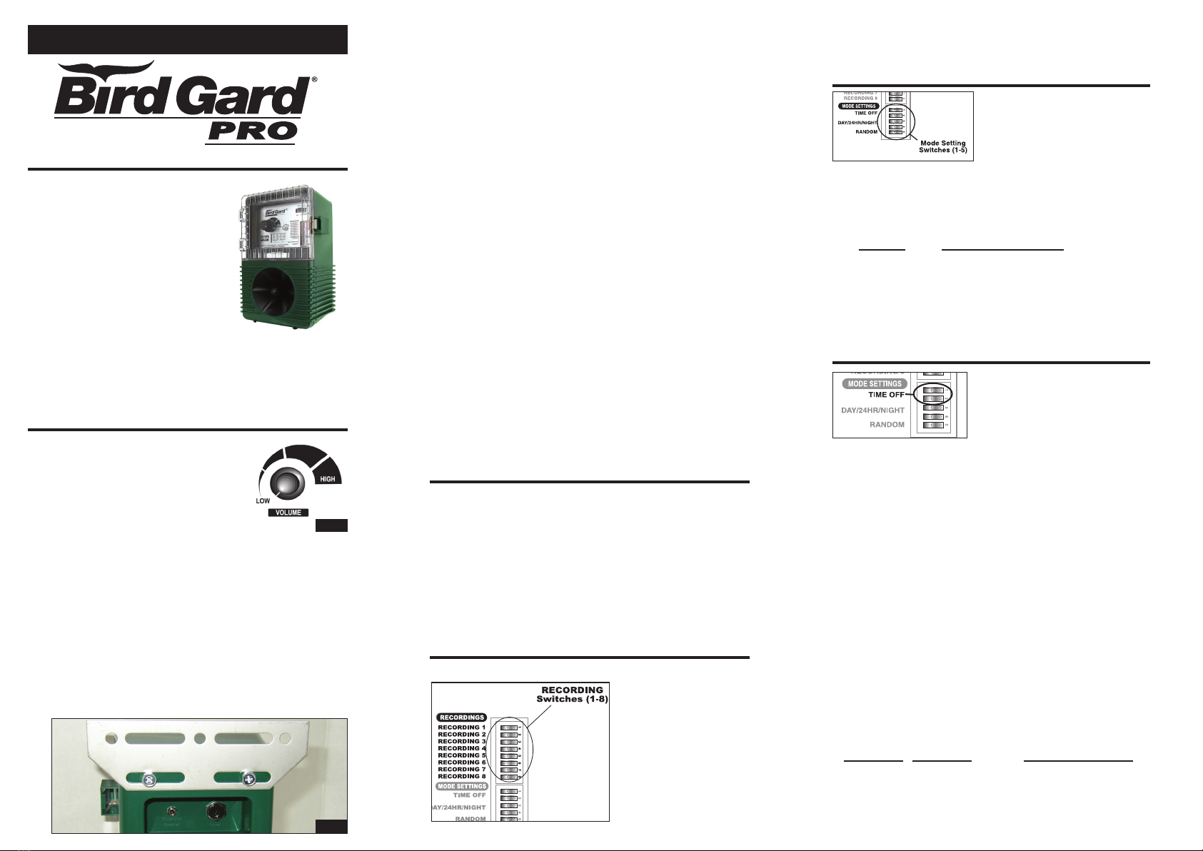
TIME OF OPERATION SWITCHES
The two “DAY/24HR/NIGHT” switches are locat-
ed just under the Time-
Off switches in the bottom
switch array. ‘Night Mode’
operates the unit at night
and ‘Day Mode’ operates
.yadehtgnirudtinueht
However, the photocell that senses the sunlight is
susceptible to bright lights. Take care notto have
bright lights shining towards the unit since this can
prevent the unit from operating properly. In 24HR
mode, the unit will operate continuously, regardless
of the time of day. To set the time period for the
unit to operate set switches 3 and 4 in the Mode
Function settings to the following:
Switch 3 Switch 4 Mode
ON OFF Day Only
OFF ON 24-Hour
ON ON Night Only
OFF OFF also Night Only
RANDOM OPERATION SWITCH
The “Random” switch is the bottom switch in the
switch array. In the Random
Mode, the unit randomly
plays the selected record-
ings in non-sequential
order. When not operating
in the Random Mode, the
unit plays the selected recordings sequentially. The
Random Mode is recommended to keep birds from
adapting to a preset pattern of sounds. To operate
the unit in Random mode, set switch 5 as follows:
Switch 5 Mode
ON Random mode ON
OFF Random mode OFF
NOTE:The unit will play for a short interval of time, from 6 sec-
onds to 48 seconds, depending on the number of sounds that
are selected.
LIMITED WARRANTY
IF YOU ARE NOT COMPLETELY SATISFIED, CONTACT THE PLACE
OF PURCHASE OR OUR CUSTOMER SERVICE DEPARTMENT
WITHIN 1 MONTH OF YOUR DATE OF PURCHASE FOR PROMPT AND
COURTEOUS REPLACEMENT, REPAIR OR REFUND.
BIRD GARD LLC'S LIABILITY HEREUNDER SHALL BE LIMITED
TO REFUNDING THE PURCHASE PRICE PAID BY CUSTOMER OR
REPLACING THE PRODUCT, IN BIRD GARD'S SOLE DISCRETION,
AND UNDER NO CIRCUMSTANCES SHALL BIRD GARD BE LIABLE
FOR ANY CONSEQUENTIAL OR INCIDENTAL DAMAGES, OF ANY
NATURE WHATSOEVER, ARISING FROM THE CUSTOMER'S USE OR
OPERATION OF THE PRODUCT; PROVIDED, HOWEVER, THAT THIS
LIMITATION MAY BE LIMITED BY STATE LAW.
EXCEPT FOR THE EXPRESS ONE-MONTH LIMITED WARRANTY
SPECIFICALLY DESCRIBED HEREIN, BIRD GARD DISCLAIMS
ALL OTHER WARRANTIES, EXPRESS OR IMPLIED, RELATING TO
THE PRODUCT, INCLUDING, BUT NOT LIMITED TO, ANY IMPLIED
WARRANTY OF MERCHANTABILITY OR IMPLIED WARRANTY OF
FITNESS; AND THE EXPRESS WARRANTIES ARE IN LIEU OF
ALL OBLIGATIONS OR LIABILITIES ON THE PART OF BIRD GARD
ARISING OUT OF OR IN CONNECTION WITH THE SALE, USE, OR
OPERATION OF THE PRODUCT.
WARRANTY IS GIVEN FOR 12 MONTHS FROM THE DATE OF PUR-
CHASE, COVERING MANUFACTURING FLAWS.
Bird Gard Pro Instructions P/N 655-0051-00 (Rev . E)
©2011 Bird Gard, LLC. All Rights Reserved
Bird Gard
®
is a patented trademark of Bird Gard, LLC.
EPA Establishment Number 075130-OR-001
P.O. Box 1690 •270 East Sun Ranch Drive
Sisters, Oregon 97759 •U.S.A.
1-888-332-2328 •Fax 541-549-5286
PROBLEM
Unit is on, but
no sound is heard
Unit is on, but plays the
same bird over and over,
regardless of settings
Unit is not operating
properly in the
DAY or NIGHT mode
Unit does not function
properly when connected
to a 12-Volt battery (when
using optional battery clip
assembly)
•Check volume settings.
•Check time of operation settings.
•Check that at least one bird is
selected to play.
•Reset the unit by turning it
off for 30 seconds and then
back on.
•Double check Mode
switch settings.
•Make sure photocell
is not obstructed.
•Make sure the photocell is
not affected by bright lights
in either the front or the
back of the unit.
•Check battery condition.
•Turn power switch on unit
to the OFF position. Then
reconnect the battery, wait
30 seconds, then switch the
unit back on.
SOLUTION
PROGRAMMING EXAMPLE
Recording Switches: Results
1, 3, 5 and 6 to “ON” position Plays Bird 1, 3, 5 & 6
Mode Switches
1 = “OFF” position
2 = “ON” position (Medium), every 1 to 4 minutes
3 = “ON” position
4 = “OFF” position Operates during daylight hours only
5 = “ON” position In random, non-sequential order
VOLUME CONTROL
The unit has a volume control dial on the front panel
of the unit (Fig. 1). Turn the dial toward LOWto
reduce sound output and rotating the dial toward
HIGHincreases sound output (VOLUME).
CAUTION: Take care when turning the dial since the unit may be
in an inactive state when the dial is rotated.It could then reactivate
at a very high level of sound which could be painful to your ears.
POWER SWITCH
.etarepoottinuehtselbanehctiwsrewopehT
.tinuehttratsotnoitisopNOehtothctiwsehtedilS
If you turn the unit OFF, be sure to leave it off for
about 30 seconds before turning it back on to allow
the electronics to properly reset.
TROUBLESHOOTING
Other manuals for Super Pro
4
Popular Control Unit manuals by other brands

Honeywell
Honeywell SILENT KNIGHT Farenhyt Series Installation and operation manual

Supermicro
Supermicro AOC-AH25G-m2S2TM user guide

BFT
BFT Rigel 4 instructions

Assa Abloy
Assa Abloy EffEff 1340-20 manual

Texas Instruments
Texas Instruments LM5164-Q1 EVM user guide

Xylem
Xylem Hoffman Specialty 792 instruction manual