BIRD THRULINE 4450 Datasheet
Other BIRD Measuring Instrument manuals
BIRD
BIRD ACM Series User manual
BIRD
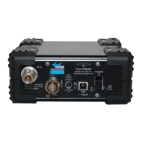
BIRD SignalHawk SH-36S-RM User manual

BIRD
BIRD 4391A User manual
BIRD
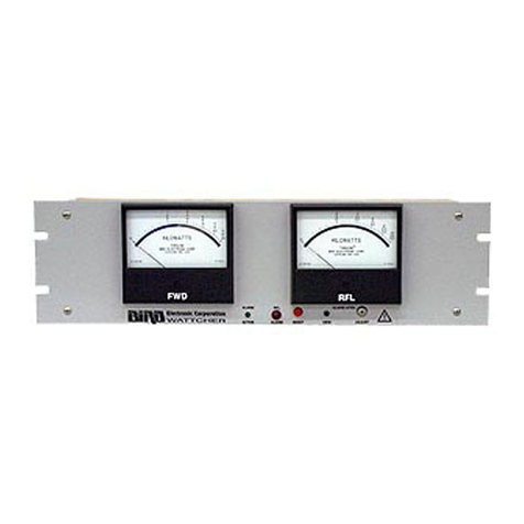
BIRD Wattcher 3126A User manual
BIRD
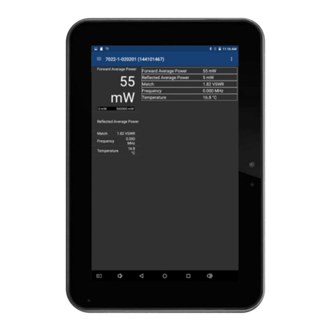
BIRD Digital Power Meter Display User manual
BIRD
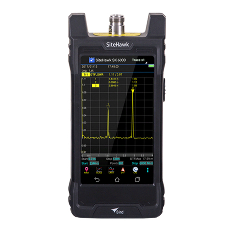
BIRD SiteHawk SK-6000-TC User manual
BIRD
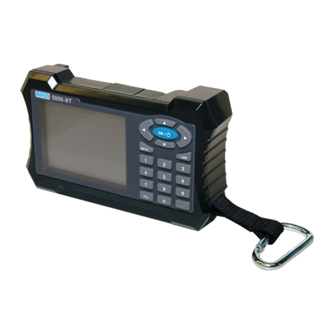
BIRD 5000-XT User manual
BIRD
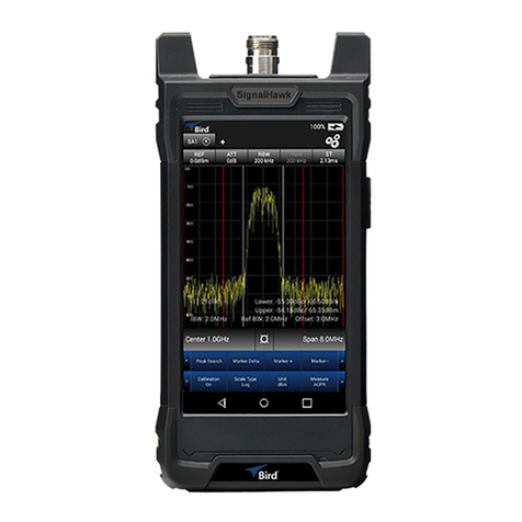
BIRD SiteHawk SK-6000 User manual
BIRD
BIRD SignalHawk SH-60S-TC User manual
BIRD
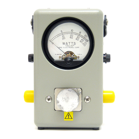
BIRD THRULINE 43 Series User manual

BIRD
BIRD Thruline 43 User manual
BIRD
BIRD Termaline 8930 Series User manual
BIRD
BIRD 7027 Series User manual

BIRD
BIRD Termaline 8920 Series User manual

BIRD
BIRD TERMLINE 8141 User manual

BIRD
BIRD 4421A User manual
BIRD
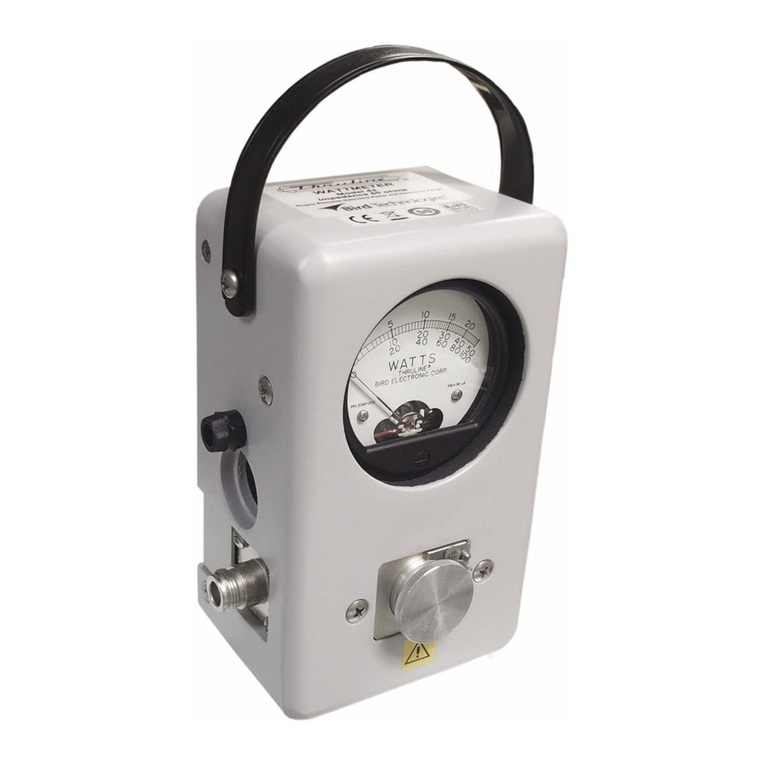
BIRD 4308 User manual
BIRD
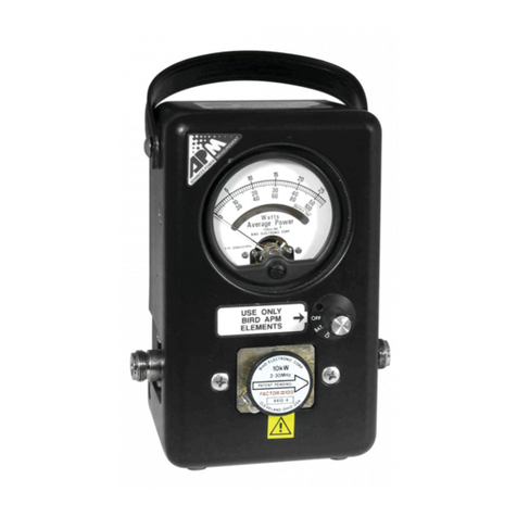
BIRD Thruline 43 User manual
BIRD
BIRD Thruline APM-16 User manual

BIRD
BIRD MRI3T User manual
Popular Measuring Instrument manuals by other brands

Powerfix Profi
Powerfix Profi 278296 Operation and safety notes

Test Equipment Depot
Test Equipment Depot GVT-427B user manual

Fieldpiece
Fieldpiece ACH Operator's manual

FLYSURFER
FLYSURFER VIRON3 user manual

GMW
GMW TG uni 1 operating manual

Downeaster
Downeaster Wind & Weather Medallion Series instruction manual

Hanna Instruments
Hanna Instruments HI96725C instruction manual

Nokeval
Nokeval KMR260 quick guide

HOKUYO AUTOMATIC
HOKUYO AUTOMATIC UBG-05LN instruction manual

Fluke
Fluke 96000 Series Operator's manual

Test Products International
Test Products International SP565 user manual

General Sleep
General Sleep Zmachine Insight+ DT-200 Service manual

