SECTION 4
OPERATION
1. GENERAL 2. LOAD POWER
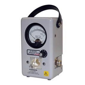
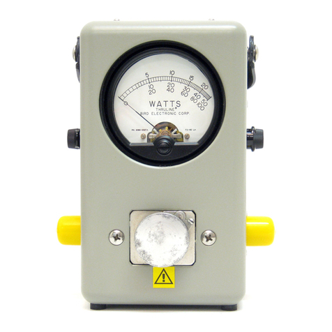
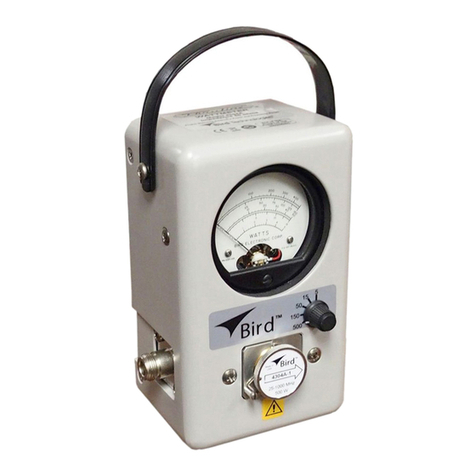
The apparent features of the THRULINE equipment
have been discussed in Section 1, GENERAL DE-
SCRIPTION, and in the Instructions of Section 3,
INSTALLATION. Measurements are made by the
insertion and operation of the Plug-In Elements pre-
viously mentioned.
The Elements determine the power range to be
read on the meter scale, and the major markings
(viz. SOW, lOOW, etc.) are the FULL SCALE POWER
value for that Element. Elements are also marked
for FREQUENCY RANGE. The transmitter fre-
quency must be within the band of the Element used.
Elements are available according to those identified
in the tables on page 4-6.
Power delivered to (and dissipated in) aload is
given by:
=Watts into Load =\^ -\^
i.e., where appreciable power is reflected, as with
an antenna, it is necessary to subtract reflected
from forward power to get load power. This cor-
rection is negligible (less than 1percent) if the load
is such as to have aVSWR of 1.2 or less. Good load
resistors, such as our TERMALINES, will thus show
negligible or unreadable reflected power.
VSWR scales, and their attendant controls, for
setting the reference point, have been intentionally
omitted from the THRULINE for two reasons:
See paragraph 6of this chapter for frequency band
flatness, and performance of the Elements outside
of stated frequencies. Elements for additional ranges
(power or frequency) may be ordered without re-
turning the THRULINE for calibration, since the RF
bodies and meters are standardized, and are de-
signed for awide range of coaxial transmission
power values and frequencies.
ARROW on Plug-In Element indicates Sensitive
DIRECTION, i.e., the direction of power flow which
the meter will read. ARROW and REVERSE are
directional terms used in reference to the THRU-
LINE ELEMENT, and mean respectively the sensi-
tive and null directions of the Element. ROTATE
ELEMENT to reverse the sensitive direction. FOR-
WARD and REFLECTED are directional terms used
in reference to the source -load circuit. Note that
the transmitter may attach to either connector of
the THRULINE. It makes no difference which ex-
ternal RF connection is selected, since the Elements
are reversible and the RF circuit is symmetrical
end for end. Before taking readings be sure that the
meter pointer has been properly zeroed under no-
power conditions.
The THRUUNE used with aTERMAUNE resistor
of proper power rating forms ahighly useful absorp-
tion wattmeter. With ARROW set toward the load,
it is unnecessary to reverse because reflected pow-
er may be neglected.
In cases where readings are being made when the
meter unit is connected to an auxiliary RF line sec-
tion body, always remove any measuring Element
from the unused RF line section. Otherwise, the dc
circuit will be unbalanced or shorted according to
the arrow position of the other Element, causing in-
accurate or no reading on the meter.
(a) Why make something similar to ahypothetical
dc volt ohmmeter with control pots for the voltmeter
multipliers? Even more complications arise when
diodes at RF are Involved.
(b) Experience using the THRULINE on trans-
mitter tune-up, antenna matching etc., i.e., on OP-
ERATING PROBLEMS shows that the power ratio 0
is no mean competitor, in practical usefulness, to
the ratio /? =VSWR.
Atrial is suggested for afew days —forret VSWR
and try thinking in terms of 0=\^ /when the
THRULINE is used. It will be noted that, even with-
out bothering to calculate the ratio exactly, the two
meter readings and give an automatic mental
impression which pictures the situation. Thus, in
an antenna matching problem, the main thing usually
is to minimize ,and anything done experimen-
tally to this end is directly indicated when the THRU-
LINE is in the reflected position. Furthermore, the
ratio of readings, only mentally evaluated, is are-
liable guide to the significance of the remaining re-
flected power.
3. GRAPH-/? VS. <> AND ITS SIGNIFICANCE
Since there are definite simple relationships
p-ri2 where VSWB
and0= W
between standing wave ratio /O and the reflected/
forward power ratio 0indicate by the THRULINE,
the latter may be conveniently used to measure
VSWR. The relationship is given in Fig. 4- la and b.
4-1
