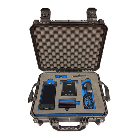
BIRD AT-800 User manual

AT-800 Antenna Tester
Operation Manual
© Copyright 2016 by Bird Technologies, Inc.
Instruction Book Part Number 920-AT800 Rev N

i
Safety Precautions
The following are general safety precautions that are not necessarily related to
any specific part or procedure, and do not necessarily appear elsewhere in this
publication. These precautions must be thoroughly understood and apply to all
phases of operation and maintenance.
WARNING
Keep Away From Live Circuits
Operating Personnel must at all times observe general
safety precautions. Do not replace components or make
adjustments to the inside of the test equipment with the
high voltage supply turned on. To avoid casualties, always
remove power.
WARNING
Shock Hazard
Do not attempt to remove the RF transmission line while
RF power is present.
WARNING
Do Not Service Or Adjust Alone
Under no circumstances should any person reach into an
enclosure for the purpose of service or adjustment of
equipment except in the presence of someone who is
capable of rendering aid.
WARNING
Safety Earth Ground
An uninterruptible earth safety ground must be supplied
from the main power source to test instruments. Grounding
one conductor of a two conductor power cable is not
sufficient protection. Serious injury or death can occur if
this grounding is not properly supplied.
WARNING
Resuscitation
Personnel working with or near high voltages should be
familiar with modern methods of resuscitation.

Safety Precautions
ii
Safety Symbols
The caution symbol appears on the equipment indicating there is
important information in the instruction manual regarding that
particular area
Note: Calls attention to supplemental information.
WARNING
Warning notes call attention to a procedure, which if not
correctly performed, could result in personal injury.
CAUTION
Caution notes call attention to a procedure, which if not
correctly performed, could result in damage to the
instrument.

AT-800 Antenna Tester
iii
Warning Statements
The following safety warnings appear in the text where there is danger to
operating and maintenance personnel, and are repeated here for emphasis.
See page 30.
On page 34.
On page 34.
WARNING
Care should be taken when handling batteries.
Do not heat or dispose of batteries in fire. May burst or release toxic
materials.
Avoid forced discharge.
Do not short circuit.
Restrict charging current and time to the recommended value.
Do not solder the battery directly.
Do not disassemble, apply excessive pressure or deform.
Avoid placing the battery in reverse polarity.
Battery disposal method should be in accordance with local and
state regulations.
WARNING
Replace with ONLY Nickel-Metal hydride (NiMH) rechargeable AA
batteries with a nominal voltage of 1.2V and minimum capacity of
2000mAh. DO NOT install any type of battery such as alkaline or
other type of secondary (chargeable) batteries.
WARNING
Charging batteries installed in reverse polarity can cause the battery
to swell or rupture.

Safety Precautions
iv
Caution Statements
The following equipment cautions appear in the text whenever the equipment
is in danger of damage and are repeated here for emphasis.
On page 12 and 30.
On page 12.
On page 14.
On page 14.
On page 29.
On page 35.
CAUTION
Follow guidelines for battery charging.
Avoid constant charging of batteries for long periods of time.
Overcharging can result in reduced battery efficiency, service life,
and possible permanent damage.
CAUTION
Required input is 11 to 16 VDC @ 250mA. Connector is wired outside
positive, inside negative.
CAUTION
AVOID STATIC DISCHARGE
Use proper Electrostatic Discharge (ESD) precautions to avoid static
discharge when making connections to the test port. Equipment
failure can occur if the test port is subjected to ESD.
CAUTION
250mW max. input
Exceeding the maximum input will cause damage to internal
components. Do not connect transmitter output to the AT-800.
Damage can also be caused by testing antennas near other
transmitting antennas. If testing base station antennas, first
measure the power at the coax end to be sure it does not exceed
250mW.
CAUTION
Harsh or abrasive detergents and some solvents can damage the
display unit and information on labels.
CAUTION
Replace with only the same type and rating fuse. 315mA 250V

AT-800 Antenna Tester
v
Safety Statements
USAGE
ANY USE OF THIS INSTRUMENT IN A MANNER NOT SPECIFIED BY
THE MANUFACTURER MAY IMPAIR THE INSTRUMENT’S SAFETY
PROTECTION.
USO
EL USO DE ESTE INSTRUMENTO DE MANERA NO ESPECIFICADA
POR EL FABRICANTE, PUEDE ANULAR LA PROTECCIÓN DE
SEGURIDAD DEL INSTRUMENTO.
BENUTZUNG
WIRD DAS GERÄT AUF ANDERE WEISE VERWENDET ALS VOM
HERSTELLER BESCHRIEBEN, KANN DIE GERÄTESICHERHEIT
BEEINTRÄCHTIGT WERDEN.
UTILISATION
TOUTE UTILISATION DE CET INSTRUMENT QUI N’EST PAS
EXPLICITEMENT PRÉVUE PAR LE FABRICANT PEUT
ENDOMMAGER LE DISPOSITIF DE PROTECTION DE
L’INSTRUMENT.
IMPIEGO
QUALORA QUESTO STRUMENTO VENISSE UTILIZZATO IN MODO
DIVERSO DA COME SPECIFICATO DAL PRODUTTORE LA
PROZIONE DI SICUREZZA POTREBBE VENIRNE COMPROMESSA.

Safety Precautions
vi
SERVICE
SERVICING INSTRUCTIONS ARE FOR USE BY SERVICE - TRAINED
PERSONNEL ONLY. TO AVOID DANGEROUS ELECTRIC SHOCK, DO
NOT PERFORM ANY SERVICING UNLESS QUALIFIED TO DO SO.
SERVICIO
LAS INSTRUCCIONES DE SERVICIO SON PARA USO EXCLUSIVO
DEL PERSONAL DE SERVICIO CAPACITADO. PARA EVITAR EL
PELIGRO DE DESCARGAS ELÉCTRICAS, NO REALICE NINGÚN
SERVICIO A MENOS QUE ESTÉ CAPACITADO PARA HACERIO.
WARTUNG
ANWEISUNGEN FÜR DIE WARTUNG DES GERÄTES GELTEN NUR
FÜR GESCHULTES FACHPERSONAL.
ZUR VERMEIDUNG GEFÄHRLICHE, ELEKTRISCHE SCHOCKS, SIND
WARTUNGSARBEITEN AUSSCHLIEßLICH VON QUALIFIZIERTEM
SERVICEPERSONAL DURCHZUFÜHREN.
ENTRENTIEN
L’EMPLOI DES INSTRUCTIONS D’ENTRETIEN DOIT ÊTRE RÉSERVÉ
AU PERSONNEL FORMÉ AUX OPÉRATIONS D’ENTRETIEN. POUR
PRÉVENIR UN CHOC ÉLECTRIQUE DANGEREUX, NE PAS
EFFECTUER D’ENTRETIEN SI L’ON N’A PAS ÉTÉ QUALIFIÉ POUR CE
FAIRE.
ASSISTENZA TECNICA
LE ISTRUZIONI RELATIVE ALL’ASSISTENZA SONO PREVISTE
ESCLUSIVAMENTE PER IL PERSONALE OPPORTUNAMENTE
ADDESTRATO. PER EVITARE PERICOLOSE SCOSSE ELETTRICHE
NON EFFETTUARRE ALCUNA RIPARAZIONE A MENO CHE
QUALIFICATI A FARLA.

AT-800 Antenna Tester
vii
UNITS ARE EQUIPPED WITH RECHAREABLE BATTERIES.
THESE ARE TO BE REPLACED BY AUTHORIZED SERVICE PERSONNEL ONLY!!!
LAS UNIDADES VIENEN EQUIPADAS CON BATERIAS
RECARGABLES.
¡¡¡Y SOLAMENTE EL PERSONAL DE SERVICIO AUTORIZADO PUEDE
REEMPLAZARLAS!!!
GERÄTE SIND MIT WIEDER AUFLADBAREN BATTERIEN
BESTÜCKT.
BATTERIEN SIND NUR VON QUALIFIZIERTEM SERICE PERSONAL
AUSZUWECHSELN!!!
CES DISPOSITIFS SONT ÉQUIPÉS DE BATTERIES
RECHARGEABLES.
SEUL LE PERSONNEL D’ENTRETIEN AUTORISÉ EST HABILITÉ À
LES REMPLACER !
LE UNITÀ SONO DOTATE DI BATTERIE RICARICABILI,
CHE DEVONO DA COME SPECIFICATO DAL PRODUTTORE LA
PROTEZIONE DI SICUREZZA POTREBBE VENIRNE
COMPROMESSA.
RF VOLTAGE MAY BE PRESENT IN RF ELEMENT SOCKET - KEEP
ELEMENT IN SOCKET DURING OPERATION.
DE LA TENSION H.F. PEAT ÊTRE PRÉSENTE DANS LA PRISE DE
L'ÉLÉMENT H.F. - CONSERVER L'ÉLÉMENT DANS LA PRISE LORS
DE L'EMPLOI.
HF-SPANNUNG KANN IN DER HF-ELEMENT-BUCHSE ANSTEHEN -
ELEMENT WÄHREND DES BETRIEBS EINGESTÖPSELT LASSEN.
PUEDE HABER VOLTAJE RF EN EL ENCHUFE DEL ELEMENTO RF -
MANTENGA EL ELEMENTO EN EL ENCHUFE DURANTE LA
OPERACION.
IL PORTAELEMENTO RF PUÒ PRESENTARE VOLTAGGIO RF -
TENERE L'ELEMENTO NELLA PRESA DURANTE IL
FUNZIONAMENTO.

About This Manual
viii
About This Manual
This manual covers the operating and maintenance instructions for the
following models:
AT-800
Changes to this Manual
We have made every effort to ensure this manual is accurate. If you discover
any errors, or if you have suggestions for improving this manual, please send
your comments to our Solon, Ohio factory. This manual may be periodically
updated. When inquiring about updates to this manual refer to the part number
and revision on the title page.
Typography
There are two types of keys on the Antenna Tester. A Hard Key is a key that has
a particular function and it is indicated on the key. These key names are set in a
bold typeface, e.g. Press the MENU key.
A Menu Select Key, (there are five under the display), will have a different label,
or name, depending on the selected function. The name will be at the bottom of
the display located directly above the corresponding key. These key names are
set in a bold Italic typeface, e.g. Press the MEAS MATCH key.
Chapter Layout
Introduction — Will help you become familiar with the parts of the Antenna
Tester, Features Available, and Optional Equipment.
Basic Operation — Everyone should read this section! This section provides
information to get the Antenna Tester powered up, helpful information about
how to operate the Antenna Tester, and time saving hints for alternate
operating methods.
Installation — This chapter contains information on how to connect the AT-
800 to antenna systems, and to power sources to charge and operate the unit.
Measure Match — Since the AT-800 Antenna Tester offers a unique method
of measuring Antenna Systems we have included the section, “Understanding
the Operating Modes.” Even if you already know the basics of antenna match
testing you might find this section useful. The remainder of the chapter provides
step by step instructions for measuring match.
Field Strength — This chapter provides step by step instructions for
measuring relative field strength of fixed cellular antennas.
Maintenance — This chapter contains the information required to keep the
AT-800 working for you. This includes battery and fuse information,
troubleshooting information, parts lists, and specifications.

ix
Table of Contents
Safety Precautions . . . . . . . . . . . . . . . . . . . . . . . . . . . . . . . . . . . . . . . . . i
Safety Symbols . . . . . . . . . . . . . . . . . . . . . . . . . . . . . . . . . . . . . . . . . . . . . . . . . . ii
Warning Statements . . . . . . . . . . . . . . . . . . . . . . . . . . . . . . . . . . . . . . . . . . . . . iii
Caution Statements . . . . . . . . . . . . . . . . . . . . . . . . . . . . . . . . . . . . . . . . . . . . . . iv
Safety Statements . . . . . . . . . . . . . . . . . . . . . . . . . . . . . . . . . . . . . . . . . . . . . . . v
About This Manual . . . . . . . . . . . . . . . . . . . . . . . . . . . . . . . . . . . . . . . viii
Changes to this Manual . . . . . . . . . . . . . . . . . . . . . . . . . . . . . . . . . . . . . . . . . . viii
Typography . . . . . . . . . . . . . . . . . . . . . . . . . . . . . . . . . . . . . . . . . . . . . . . . . . . viii
Chapter Layout . . . . . . . . . . . . . . . . . . . . . . . . . . . . . . . . . . . . . . . . . . . . . . . . viii
Chapter 1 Introduction . . . . . . . . . . . . . . . . . . . . . . . . . . . . . . . . . . . . . 1
Items Supplied . . . . . . . . . . . . . . . . . . . . . . . . . . . . . . . . . . . . . . . . . . . . . . . . . . 1
Component Description . . . . . . . . . . . . . . . . . . . . . . . . . . . . . . . . . . . . . . . . . . 2
Display Description . . . . . . . . . . . . . . . . . . . . . . . . . . . . . . . . . . . . . . . . . . . . . . 4
Features . . . . . . . . . . . . . . . . . . . . . . . . . . . . . . . . . . . . . . . . . . . . . . . . . . . . . . . 6
Optional Equipment . . . . . . . . . . . . . . . . . . . . . . . . . . . . . . . . . . . . . . . . . . . . . 6
Chapter 2 Basic Operations . . . . . . . . . . . . . . . . . . . . . . . . . . . . . . . . . 7
Getting Started . . . . . . . . . . . . . . . . . . . . . . . . . . . . . . . . . . . . . . . . . . . . . . . . . 7
Messages . . . . . . . . . . . . . . . . . . . . . . . . . . . . . . . . . . . . . . . . . . . . . . . . . . . 9
Out of Range Values . . . . . . . . . . . . . . . . . . . . . . . . . . . . . . . . . . . . . . . . . . 9
Selecting the Cellular System . . . . . . . . . . . . . . . . . . . . . . . . . . . . . . . . . . . 9
Setting the Auto Shut-Off Timer . . . . . . . . . . . . . . . . . . . . . . . . . . . . . . . . 10
Return to Factory Presets . . . . . . . . . . . . . . . . . . . . . . . . . . . . . . . . . . . . . 10
Set Serial Baud Rate . . . . . . . . . . . . . . . . . . . . . . . . . . . . . . . . . . . . . . . . . 11
Chapter 3 Installation . . . . . . . . . . . . . . . . . . . . . . . . . . . . . . . . . . . . . 12
Power Supply . . . . . . . . . . . . . . . . . . . . . . . . . . . . . . . . . . . . . . . . . . . . . . . . . . 12
AC Mains Adapter . . . . . . . . . . . . . . . . . . . . . . . . . . . . . . . . . . . . . . . . . . . 12
Automobile Cigarette Lighter Adapter Cable . . . . . . . . . . . . . . . . . . . . . 13
Connecting the Antenna . . . . . . . . . . . . . . . . . . . . . . . . . . . . . . . . . . . . . . . . . 14
Chapter 4 Measure Match. . . . . . . . . . . . . . . . . . . . . . . . . . . . . . . . . .15
Understanding the Operating Modes . . . . . . . . . . . . . . . . . . . . . . . . . . . . . . 15
Swept Frequency vs. Single Frequency . . . . . . . . . . . . . . . . . . . . . . . . . . 15
Band Selection Presets vs. User Defined . . . . . . . . . . . . . . . . . . . . . . . . . 16
Measurement Units . . . . . . . . . . . . . . . . . . . . . . . . . . . . . . . . . . . . . . . . . . 16
Auto Scale vs. Manual Scale . . . . . . . . . . . . . . . . . . . . . . . . . . . . . . . . . . . 17
Sweep Type – Single Hold vs. Continuous . . . . . . . . . . . . . . . . . . . . . . . . 18
Swept Frequency . . . . . . . . . . . . . . . . . . . . . . . . . . . . . . . . . . . . . . . . . . . . . . . 19
Table of Contents
x
Select Frequency Band - Presets . . . . . . . . . . . . . . . . . . . . . . . . . . . . . . . 19

Select Frequency Band - User Defined . . . . . . . . . . . . . . . . . . . . . . . . . . . 19
Select Measurement Units . . . . . . . . . . . . . . . . . . . . . . . . . . . . . . . . . . . . 20
Select Auto or Manual Scale . . . . . . . . . . . . . . . . . . . . . . . . . . . . . . . . . . . 20
Selecting the Sweep Type . . . . . . . . . . . . . . . . . . . . . . . . . . . . . . . . . . . . . 21
Saving a Trace . . . . . . . . . . . . . . . . . . . . . . . . . . . . . . . . . . . . . . . . . . . . . . . . . 22
Recalling a Trace . . . . . . . . . . . . . . . . . . . . . . . . . . . . . . . . . . . . . . . . . . . . . . . 23
Clearing a Trace . . . . . . . . . . . . . . . . . . . . . . . . . . . . . . . . . . . . . . . . . . . . . . . . 23
Limit Testing . . . . . . . . . . . . . . . . . . . . . . . . . . . . . . . . . . . . . . . . . . . . . . . . . . . 24
Turn Audio On/Off . . . . . . . . . . . . . . . . . . . . . . . . . . . . . . . . . . . . . . . . . . . 24
Selecting Limit Values . . . . . . . . . . . . . . . . . . . . . . . . . . . . . . . . . . . . . . . . 24
Using a Trace as the Limit . . . . . . . . . . . . . . . . . . . . . . . . . . . . . . . . . . . . . 25
Clearing a Limit . . . . . . . . . . . . . . . . . . . . . . . . . . . . . . . . . . . . . . . . . . . . . 25
Single Frequency . . . . . . . . . . . . . . . . . . . . . . . . . . . . . . . . . . . . . . . . . . . . . . . 26
Selecting the Frequency - User Defined . . . . . . . . . . . . . . . . . . . . . . . . . 26
Selecting the Frequency - Automatically . . . . . . . . . . . . . . . . . . . . . . . . . 26
Select Measurement Units . . . . . . . . . . . . . . . . . . . . . . . . . . . . . . . . . . . . 26
Select Auto or Manual Scale . . . . . . . . . . . . . . . . . . . . . . . . . . . . . . . . . . . 27
Turn Audio On/Off . . . . . . . . . . . . . . . . . . . . . . . . . . . . . . . . . . . . . . . . . . . 27
Chapter 5 Field Strength. . . . . . . . . . . . . . . . . . . . . . . . . . . . . . . . . . . 28
Field Strength Measurement . . . . . . . . . . . . . . . . . . . . . . . . . . . . . . . . . . . . . 28
Turn Audio On/Off . . . . . . . . . . . . . . . . . . . . . . . . . . . . . . . . . . . . . . . . . . . 28
Enter Gain Factor / Select Auto Gain . . . . . . . . . . . . . . . . . . . . . . . . . . . . 28
Chapter 6 Maintenance . . . . . . . . . . . . . . . . . . . . . . . . . . . . . . . . . . . .29
Cleaning . . . . . . . . . . . . . . . . . . . . . . . . . . . . . . . . . . . . . . . . . . . . . . . . . . . . . . 29
Calibration . . . . . . . . . . . . . . . . . . . . . . . . . . . . . . . . . . . . . . . . . . . . . . . . . . . . 29
Charging Batteries . . . . . . . . . . . . . . . . . . . . . . . . . . . . . . . . . . . . . . . . . . . . . . 30
Batteries and Long Term Storage . . . . . . . . . . . . . . . . . . . . . . . . . . . . . . . . . . 30
Operational Tests . . . . . . . . . . . . . . . . . . . . . . . . . . . . . . . . . . . . . . . . . . . . . . 31
Power-up . . . . . . . . . . . . . . . . . . . . . . . . . . . . . . . . . . . . . . . . . . . . . . . . . . 31
Battery Test . . . . . . . . . . . . . . . . . . . . . . . . . . . . . . . . . . . . . . . . . . . . . . . . 31
Display Test . . . . . . . . . . . . . . . . . . . . . . . . . . . . . . . . . . . . . . . . . . . . . . . . 32
Self Test . . . . . . . . . . . . . . . . . . . . . . . . . . . . . . . . . . . . . . . . . . . . . . . . . . . 33
Battery Replacement . . . . . . . . . . . . . . . . . . . . . . . . . . . . . . . . . . . . . . . . . . . . 34
Fuse Replacement . . . . . . . . . . . . . . . . . . . . . . . . . . . . . . . . . . . . . . . . . . . . . . 35
Troubleshooting . . . . . . . . . . . . . . . . . . . . . . . . . . . . . . . . . . . . . . . . . . . . . . . . 36
The Antenna Tester will not power up . . . . . . . . . . . . . . . . . . . . . . . . . . 36

AT-800 Antenna Tester
xi
NVRAM Test Fails . . . . . . . . . . . . . . . . . . . . . . . . . . . . . . . . . . . . . . . . . . . . 36
ROM, EEPROM, RAM, A/D, TEMPR, PLL Test Fails . . . . . . . . . . . . . . . . . 36
Stuck Keys Test Fails . . . . . . . . . . . . . . . . . . . . . . . . . . . . . . . . . . . . . . . . . 36
“Noise” is Displayed During Testing . . . . . . . . . . . . . . . . . . . . . . . . . . . . . 36
Antenna Tester indicates a Perfect Match . . . . . . . . . . . . . . . . . . . . . . . 37
Customer Service . . . . . . . . . . . . . . . . . . . . . . . . . . . . . . . . . . . . . . . . . . . . . . . 37
Parts List . . . . . . . . . . . . . . . . . . . . . . . . . . . . . . . . . . . . . . . . . . . . . . . . . . . . . . 38
Specifications . . . . . . . . . . . . . . . . . . . . . . . . . . . . . . . . . . . . . . . . . . . . . . . . . . 39
Menu Structure . . . . . . . . . . . . . . . . . . . . . . . . . . . . . . . . . . . . . . . . . . . . . . . . 40
Limited Warranty . . . . . . . . . . . . . . . . . . . . . . . . . . . . . . . . . . . . . . . . . 41

1
Chapter 1 Introduction
Items Supplied
Figure 1 Supplied Items
1. Bird AT-800
2. AC Mains Adapter
3. Female TNC Connector
4. Field Strength Antenna
5. Operation Manual (not shown)

AT-800 Antenna Tester
2
Component Description
Figure 2 Component Description

Introduction
3
1. LCD Display Backlit liquid crystal display.
2. External DC
Connector
Connect either the ac adapter or the
cigarette lighter adapter cable. External
supplies operate the unit and charge
the internal battery.
3. Cursor Keys
Left Arrow Press in swept frequency mode to
move the cursor to the left. Press during
data entry to erase data.
Right Arrow Press in swept frequency mode to
move the cursor to the right.
Up Arrow Moves the cursor to the maximum point
on the displayed trace. Press during
data entry to increase numeric data.
Down Arrow Moves the cursor to the minimum point
on the displayed trace. Press during
data entry to decrease numeric data.
4. Backlight Key Turns the backlight on or off. Backlight
is on a timer to increase battery life.
5. On Key Press to turn tester on, press and hold
to turn tester off.
6. +/- Key Toggles between positive and negative
numbers.
7. Enter Key Completes data entry.
8. ESC Key Back up through menu structure. At the
top menu level, blanks menu. Exits data
entry without saving changes.
9. Menu Key Displays software menu and enables
menu select keys.
10. Select Key Allows current parameter, indicated by
flashing cursor, to be changed. Press
again to enable the next parameter to
be changed.
11. Numeric Keys Input numeric values.
12. Menu Select
Keys
Used to access the menu sections
described directly above them. Can
also be used to scroll through available
settings in a particular parameter.
13. Test Port Connect antenna or antenna lead.
14. Serial Port Connect communication cable to allow
data transfer to a PC.

AT-800 Antenna Tester
4
Display Description
Figure 3 Display Description

Introduction
5
1. Sweep Rate
Indicator
Blinks when sweeping.
2. Measurement Units Indicates selected measurement
units.
3. Trace Graphic display of measured
results across selected frequency
band.
4. Menu Select Key
Labels
Defines function of menu select
keys located below the display.
5. Frequency Band
Scale
Displays frequency band selected.
6. Cursor Used to select measurement
position on the trace.
7. Utility Label Area for displaying general data
(Lo Batt, Busy, Hold, Noise, and
test results).
8. Band Indicates selected band for cellular
system defined, (Tx, Rx, TxRx, or
User).
9. Base/Mobile
Indicator
Indicates Base or Mobile selection.
10. Cellular System Indicates cellular system selected
(AMPS, GSM, PDC, CT-2, CT-2
Korea).
11. Frequency Selected Frequency (for swept
mode this is frequency at the
cursor position).
12. Measured Value Numeric display of measured value
(for swept mode this is the value at
the cursor position).
13. Scale Displays user defined
measurement scale.
14. Pointer Moves across scale to show
analog indication of measured
value.
15. Channel Channel number corresponding to
selected frequency.

AT-800 Antenna Tester
6
Features
Swept Frequency Mode — Fast scan shows Voltage Standing Wave Ratio
(VSWR); Reflection Coefficient (); % Match, or Return Loss (dB) across an entire
band. A movable cursor can be used to pinpoint a scan frequency and the
corresponding measurement value is displayed.
Single Frequency Mode — Provides measurement information in units of
VSWR, , match efficiency or return loss at one frequency on a simulated meter
movement. An audio generator can be enabled to produce a tone that is
proportional to the match condition.
Auto Scaling — Used in either swept or single frequency modes, sets the Y
axis for best measurement display.
Relative Field Strength — Verifies output of portable cellular phones with
fixed antennas.
Cellular System Presets — Pre-programmed band segments for AMPS,
GSM, PDC, CT-2, and CT-2 Korea cellular testing.
Limit Testing — Quick pass-fail indication; compares measurements to user
selected limits.
Data Storage — Saves and recalls up to 12 traces to be used to set limit or
long term monitoring of antenna performance.
Serial Communication Link — Built in serial port and optional software
uploads data to a personal computer for analysis or storage.
Optional Equipment
Automobile Cigarette Lighter Adapter Cable (P/N 5A2238-1) —
Connects tester to standard 12V automotive cigarette lighter jack.
Carrying Case (P/N 5000-030) — Convenient and protective, large enough
to carry the tester, AC adapter, connectors, field strength antenna and
instruction book.
Verification Kit (P/N 7000A845) — Used to verify tester performance.
Includes standard mismatch and connector adapter.
Interface Software (P/N 7000B840) — PC software used to upload trace
data for analysis, printing or storage.
Note: System requirements: IBM PC or equivalent; Windows 95 or
later, 6 MB free hard disk space; VGA monitor, open com port.
Includes interface cable.

7
Chapter 2 Basic Operations
Getting Started
This section describes initial quick steps to get started. For detailed information
regarding connecting the Antenna Tester refer to
"Connecting the Antenna"
on page 14
Note: This unit is shipped with the batteries not charged. Charge
batteries for at least 8 hours before use.
Power On/Off
To turn the Antenna Tester on, momentarily press the ON key. The
results of a self test will be displayed if a failure is present. For more
information about the self test or a failure, refer to
"Maintenance" on
page 29
.
To turn the Antenna Tester off, press and hold the ON key for 1
second.
Backlight
To turn the backlight on, press the
BACKLIGHT key.
To increase or decrease display contrast, press and hold the
BACKLIGHT key while pressing either the UP or DOWN arrow key.
To turn the backlight off, press the
BACKLIGHT key.
Software Menu
Press the MENU key to display the software menu.
Blinking Cursor (black square)
The cursor will be blinking in the selected area, indicating that the parameter for
that area can be changed.

AT-800 Antenna Tester
8
Enter Key
All data entry, and mode changes accessed using select key, require the enter
key to be pressed before they are initiated.
Up/Down Arrow Keys
When a function is enabled for change, the UP or DOWN arrow keys can be
used to either scroll through choices or increase/decrease the numerical value.
The actual increments depend on the function.
Left Arrow Key
The LEFT arrow key can be used to backspace, erasing one character at a time,
during data entry.
Escape (ESC)
Returns to previous menu without initiating a change.
Select Key
The instructions in this manual are based on stepping through the software
menu using the keys below the display. Once comfortable operating the AT-800,
it may be faster to use the SELECT key to access some functions. These
include: Units, Scale, Start and Stop Frequencies in swept frequency mode and
Units, Scale, Frequency and Channel in single frequency mode.
Press the SELECT key until the cursor is blinking at the desired function. The
first function enabled depends on the last function selected through the menu.
Other manuals for AT-800
1
Table of contents
Other BIRD Test Equipment manuals

BIRD
BIRD AT-800 User manual

BIRD
BIRD TERMLINE 8141 User manual

BIRD
BIRD 4029 User manual

BIRD
BIRD FlightHawk User manual

BIRD
BIRD AT-400 Antenna Tester AT-400 User manual

BIRD
BIRD AT-500 User manual

BIRD
BIRD SMK-3000 Series User manual

BIRD
BIRD ECONOLOAD 8730 Series User manual

BIRD
BIRD SignalHawk SH-36S-RM User manual