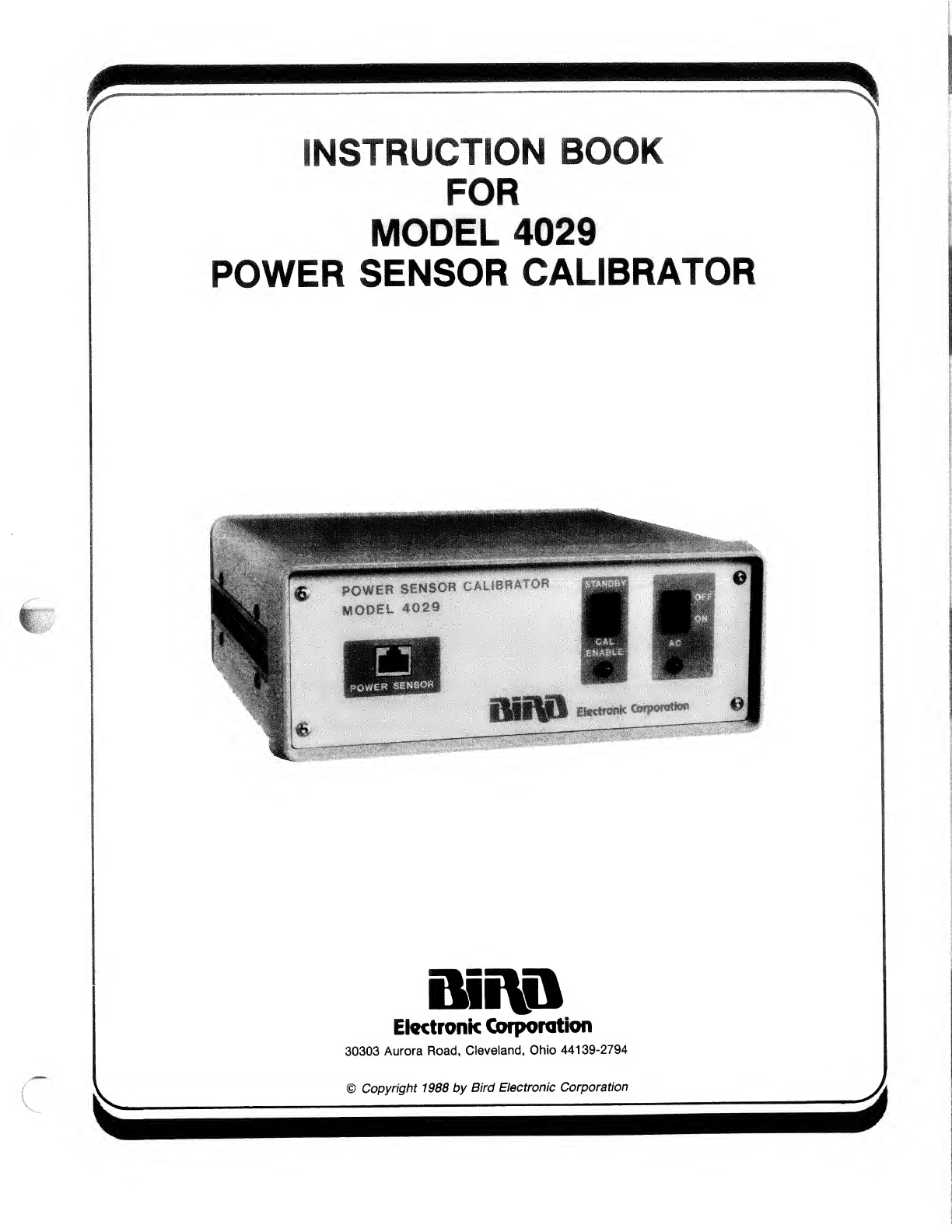
MODEL 4029 POWER SENSOR CALIBRATOR
INTRODUCTION
PURPOSE AND FUNCTION
This manual provides the information required for op-
erating and maintaining the Bird Electronic Corpo-
ration Model 4029 Power Sensor Calibrator. It also
serves as aguideline for calibrating 4020 series
power sensors. Throughout this manual the Model
4029 will be referred to as the calibrator.
CAPABILITIES
The calibrator is an accessory for the 4420 series of
Power Meters. It is amicroprocessor-based instru-
ment that is used for calibrating the 4020 Series RF
Power Sensors. Each power sensor contains up to
forty calibration factor vs. frequency points stored in
non-volatile memory. The calibrator and an external
CRT terminal (not supplied) provides access to the
power sensor memory in order to add or delete in-
dividual calibration points, clear all calibration points,
or simply list calibration points for review. The spec-
ifications for the calibrator are listed in Table 1-1.
TABLE 1-1. SPECIFICATIONS FOR MODEL 4029
POWER SENSOR CALIBRATOR
Calibration Transfer
Accuracy ±2% of RF Power Standard Accuracy
Communications
Baud Rates Selectable. 50, 75, 110, 135, 150, 300,
600, 1200, 1800, 2400, 3600, 4800,
7200, 9600, and 19200 Baud.
Data Format Asynchronous. 5, 6, 7, or 8data bits,
1or 2stop bits selectable.
Data Code ASCII Standard
AC Power 115 or 230 Vac +10%, 45-66Hz. 9.0
Va.
Fuse SAG 0.1 5A 250V
EMI Compliance Exceeds FCC Class Arequirements
for computing devices. (Both radiated
and conducted emission.)
Temperature Range
Operating
Storage +20°C to +30°C (68° Fto 86°F)
-10°C to +70°C (14°F to 158°F)
Dimensions 105/i6"Lx10V8"Wx4V4"D
(262mm x257mm x108mm)
Weight 5V4 lb. (2.4kg)
ADDITIONAL EQUIPMENT REQUIRED BUT NOT
SUPPLIED
a. Serial CRT Terminal —Aserial terminal is used
to transfer information between the calibrator and
the user. It must be compatible with an RS-232
format for standard communications of ASCII
coded data. The calibrator has selectable data for-
mat and baud rates to match most serial termi-
nals. (Refer to Table 2-1). All data is displayed in
astandard 24 lines by 80 columns format. Most
personal computers can be configured as a serial
terminal. Appendix Acontains aprogram that al-
lows an IBM PC computer to be used as ater-
minal.
b. RF Power Source —ARF Power Source provides
the reference power level to the power sensor
during calibration. It must be capable of producing
stable CW power into 50 ohms at all of the cali-
brating frequencies. Each harmonic of the RF sig-
nal must be at least 50 db less than the
fundamental signal. Any residual amplitude mod-
ulation must be less than 0.5%. The above re-
quirements can be easily achieved by using a
combination of asignal generator and abroad
band power amplifier with proper filtering.
c. RF Power Meter Standard The power meter
standard is used to accurately measure the CW
power applied to the power sensor during cali-
bration. The calibrator transfers the accuracy of
the power meter standard to the power sensor.
The accuracy of final calibration is highly depend-
ent on the accuracy of the power meter standard.
Aside from being accurate, it must also be able to
operate over the frequency range and power level
of the RF power source. Input SWR should be low
to keep mismatch errors to aminimum.
d. Serial Communication Cable —A25 conductor
serial communications cable is used to connect
the calibrator to the serial CRT terminal. The cal-
ibrator end should be serviced with aStandard
DB25 (25 pin male “D”) connector. The terminal
end should be serviced with aconnector to mate
with the serial output port of your terminal. Con-
sult your terminal manual for the correct connec-
tor configuration. Bird Electronic Corporation
offers two different lengths of cable assemblies
for use with the calibrator (P/N 5-1662-1, 5feet
or 5-1662-2, 10 feet).
The following equipment is required to calibrate 4020
Series RF Power Sensors but is not supplied with
the calibrator.
-1-
4029