BIRD SMK-3000 Series User manual

SMK-3000 Series
RF Calibration Kit
User Manual
©
Copyright 2022
by Bird Technologies, Inc.
Technical Manual Part Number 920-4022A600 Rev B
Thruline® is a Registered Trademark
of Bird Technologies, Inc.


Safety Precautions
i
Safety Precautions
The following are general safety precautions that are not necessarily related to any specific part or procedure, and
do not necessarily appear elsewhere in this publication. These precautions must be thoroughly understood and
apply to all phases of operation and maintenance.
WARNING
Keep Away From Live Circuits
Operating Personnel must at all times observe general safety precautions. Do not replace
components or make adjustments to the inside of the test equipment with the high voltage
supply turned on. To avoid casualties, always remove power.
WARNING
Shock Hazard
Do not attempt to remove the RF transmission line while RF power is present.
WARNING
Do Not Service Or Adjust Alone
Under no circumstances should any person reach into an enclosure for the purpose of
service or adjustment of equipment except in the presence of someone who is capable of
rendering aid.
WARNING
Safety Earth Ground
An uninterruptible earth safety ground must be supplied from the main power source to
test instruments. Grounding one conductor of a two conductor power cable is not
sufficient protection. Serious injury or death can occur if this grounding is not properly
supplied.
WARNING
Resuscitation
Personnel working with or near high voltages should be familiar with modern methods of
resuscitation.
WARNING
Remove Power
Observe general safety precautions. Do not open the instrument with the power on.

RF Calibration Kit
ii
Safety Symbols
Note: Highlights an essential operating or maintenance procedure, condition, or statement
WARNING
Highlights an essential operating or maintenance procedure, practice, condition,
statement, etc, which, if not strictly observed, could result in injury to, or death of,
personnel or long term health hazards.
CAUTION
Highlights an essential operating or maintenance procedure, practice, condition,
statement, etc, which, if not strictly observed, could result in damage to, or destruction of,
equipment or loss of mission effectiveness.

Safety Precautions
iii
Warning Statements
The following safety warnings appear in the text where there is danger to operating and maintenance personnel and
are repeated here for emphasis.
See page 15, 17, and 18.
See page 18.
See page 18.
WARNING
Never attempt to connect or disconnect RF equipment from the transmission line while RF
power is being applied. Leaking RF energy is a potential health hazard.
WARNING
To avoid personal injury, disconnect the power cord from the AC line before performing any
maintenance.
WARNING
The Bird 4421A contains no user-serviceable parts.
Do not open the cover.

RF Calibration Kit
iv
Caution Statements
The following equipment cautions appear in the text whenever the equipment is in danger of damage and are
repeated here for emphasis.
See page 3 and 19.
See page 15.
See page 16 and 21.
See page 18.
See page 19.
See page 26.
CAUTION
Only connectors that are in good condition should be used with the RF Power Sensor.
Damaged, worn, or improperly fitting connectors could impact the accuracy of field
RF measurements.
CAUTION
Do not exceed the RF Power or RF frequency specifications of the RF Power Sensor.
CAUTION
Do not over tighten the screws. Over tightening will strip the plastic and the screw will not
hold the 4421A to the VESA mount.
CAUTION
Do not use harsh or abrasive detergents for cleaning.
CAUTION
Due to the complexity of the Bird Power Sensor, field repairs should not be attempted.
Removal or disturbance of the power sensor cover can result in cancellation of the
warranty.
CAUTION
Do not store the 4421A outside the following temperature ranges
-10° to 50°C, ≤ 1 month
-10° to 35°C, ≤ 6 months
-10° to 25°C, > 6 months
Storage outside these temperature ranges may degrade battery capacity.

Safety Precautions
v
Safety Statements
USAGE
ANY USE OF THIS INSTRUMENT IN A MANNER NOT SPECIFIED BY THE MANUFACTURER MAY
IMPAIR THE INSTRUMENT’S SAFETY PROTECTION.
USO
EL USO DE ESTE INSTRUMENTO DE MANERA NO ESPECIFICADA POR EL FABRICANTE, PUEDE
ANULAR LA PROTECCIÓN DE SEGURIDAD DEL INSTRUMENTO.
BENUTZUNG
WIRD DAS GERÄT AUF ANDERE WEISE VERWENDET ALS VOM HERSTELLER BESCHRIEBEN,
KANN DIE GERÄTESICHERHEIT BEEINTRÄCHTIGT WERDEN.
UTILISATION
TOUTE UTILISATION DE CET INSTRUMENT QUI N’EST PAS EXPLICITEMENT PRÉVUE PAR LE
FABRICANT PEUT ENDOMMAGER LE DISPOSITIF DE PROTECTION DE L’INSTRUMENT.
IMPRIEGO
QUALORA QUESTO STRUMENTO VENISSE UTILIZZATO IN MODO DIVERSO DA COME
SPECIFICATO DAL PRODUTTORE LA PROZIONE DI SICUREZZA POTREBBE VENIRNE
COMPROMESSA.
SERVICE
SERVICING INSTRUCTIONS ARE FOR USE BY SERVICE-TRAINED PERSONNEL ONLY. TO AVOID
DANGEROUS ELECTRIC SHOCK, DO NOT PERFORM ANY SERVICING UNLESS QUALIFIED TO DO
SO.
SERVICIO
LAS INSTRUCCIONES DE SERVICIO SON PARA USO EXCLUSIVO DEL PERSONAL DE SERVICIO
CAPACITADO. PARA EVITAR EL PELIGRO DE DESCARGAS ELÉCTRICAS, NO REALICE NINGÚN
SERVICIO A MENOS QUE ESTÉ CAPACITADO PARA HACERIO.
WARTUNG
ANWEISUNGEN FÜR DIE WARTUNG DES GERÄTES GELTEN NUR FÜR GESCHULTES
FACHPERSONAL.
ZUR VERMEIDUNG GEFÄHRLICHE, ELEKTRISCHE SCHOCKS, SID WARTUNGSARBEITEN
AUSSCHLIEßLICH VON QUALIFIZIERTEM SERVICEPERSONAL DURCHZUFÜHREN.
ENTRENTIEN
L’EMPLOI DES INSTRUCTIONS D’ENTRETIEN DOIT ÊTRE RÉSERVÉ AU PERSONNEL FORMÉ AUX
OPÉRATIONS D’ENTRETIEN. POUR PRÉVENIR UN CHOC ÉLECTRIQUE DANGEREUX, NE PAS
EFFECTUER D’ENTRETIEN SI L’ON N’A PAS ÉTÉ QUALIFIÉ POUR CE FAIRE.
ASSISTENZA TECNICA
LE ISTRUZIONI RELATIVE ALL’ASSISTENZA SONO PREVISTE ESCLUSIVAMENTE PER IL
PERSONALE OPPORTUNAMENTE ADDESTRATO. PER EVITARE PERICOLOSE SCOSSE
ELETTRICHE NON EFFETTUARRE ALCUNA RIPARAZIONE A MENO CHE QUALIFICATI A FARLA.

RF Calibration Kit
vi
About This Manual
This manual covers the operating & maintenance instructions for the following models:
Changes to this Manual
We have made every effort to ensure this manual is accurate. If you should discover any errors, or if you have
suggestions for improving this manual, please send your comments to our factory. This manual may be periodically
updated. When inquiring about updates to this manual refer to the part number and revision level on the title page.
SMK-3003A

vii
Table of Contents
Safety Precautions . . . . . . . . . . . . . . . . . . . . . . . . . . . . . . . . . . . . . . . . . . . . . . . . . . . . . . . . . . . . . . . . . . .i
Safety Symbols . . . . . . . . . . . . . . . . . . . . . . . . . . . . . . . . . . . . . . . . . . . . . . . . . . . . . . . . . . . . . . . . . . . . . . . . . . . . . . . . ii
Warning Statements . . . . . . . . . . . . . . . . . . . . . . . . . . . . . . . . . . . . . . . . . . . . . . . . . . . . . . . . . . . . . . . . . . . . . . . . . . . iii
Caution Statements . . . . . . . . . . . . . . . . . . . . . . . . . . . . . . . . . . . . . . . . . . . . . . . . . . . . . . . . . . . . . . . . . . . . . . . . . . . .iv
Safety Statements . . . . . . . . . . . . . . . . . . . . . . . . . . . . . . . . . . . . . . . . . . . . . . . . . . . . . . . . . . . . . . . . . . . . . . . . . . . . . . v
About This Manual . . . . . . . . . . . . . . . . . . . . . . . . . . . . . . . . . . . . . . . . . . . . . . . . . . . . . . . . . . . . . . . . . . . . . . . . . . . . .vi
Changes to this Manual . . . . . . . . . . . . . . . . . . . . . . . . . . . . . . . . . . . . . . . . . . . . . . . . . . . . . . . . . . . . . . . . . . . . . . . . .vi
Chapter 1 Introduction . . . . . . . . . . . . . . . . . . . . . . . . . . . . . . . . . . . . . . . . . . . . . . . . . . . . . . . . . . . . . . . 1
RF Calibration Kit . . . . . . . . . . . . . . . . . . . . . . . . . . . . . . . . . . . . . . . . . . . . . . . . . . . . . . . . . . . . . . . . . . . . . . . . . . . . . . 1
Items Supplied in the SMK-3003, 3% Accuracy RF Calibration Kit . . . . . . . . . . . . . . . . . . . . . . . . . . . . . . . . . . . . 1
RF Power Sensor Theory of Operation . . . . . . . . . . . . . . . . . . . . . . . . . . . . . . . . . . . . . . . . . . . . . . . . . . . . . . . . . . . . . 2
4421A RF Power Meter . . . . . . . . . . . . . . . . . . . . . . . . . . . . . . . . . . . . . . . . . . . . . . . . . . . . . . . . . . . . . . . . . . . . . . . . . 2
Optional Rack Mount Kit . . . . . . . . . . . . . . . . . . . . . . . . . . . . . . . . . . . . . . . . . . . . . . . . . . . . . . . . . . . . . . . . . . . . . 2
Chapter 2 Equipment Description. . . . . . . . . . . . . . . . . . . . . . . . . . . . . . . . . . . . . . . . . . . . . . . . . . . . . . 3
RF Power Sensor Equipment Description . . . . . . . . . . . . . . . . . . . . . . . . . . . . . . . . . . . . . . . . . . . . . . . . . . . . . . . . . . . 3
Display Options . . . . . . . . . . . . . . . . . . . . . . . . . . . . . . . . . . . . . . . . . . . . . . . . . . . . . . . . . . . . . . . . . . . . . . . . . . . . . 3
Quick-Change Connectors . . . . . . . . . . . . . . . . . . . . . . . . . . . . . . . . . . . . . . . . . . . . . . . . . . . . . . . . . . . . . . . . . . . . 3
Power Sensor RF / Interface Connectors . . . . . . . . . . . . . . . . . . . . . . . . . . . . . . . . . . . . . . . . . . . . . . . . . . . . . . . . 4
4421A RF Power Meter Equipment Description . . . . . . . . . . . . . . . . . . . . . . . . . . . . . . . . . . . . . . . . . . . . . . . . . . . . . 5
4421A Controls and Indicators . . . . . . . . . . . . . . . . . . . . . . . . . . . . . . . . . . . . . . . . . . . . . . . . . . . . . . . . . . . . . . . . 6
Display Controls and Indicators . . . . . . . . . . . . . . . . . . . . . . . . . . . . . . . . . . . . . . . . . . . . . . . . . . . . . . . . . . . . . . . . 7
Settings Menu . . . . . . . . . . . . . . . . . . . . . . . . . . . . . . . . . . . . . . . . . . . . . . . . . . . . . . . . . . . . . . . . . . . . . . . . . . . . . . 9
Graph Settings Menu . . . . . . . . . . . . . . . . . . . . . . . . . . . . . . . . . . . . . . . . . . . . . . . . . . . . . . . . . . . . . . . . . . . . . . . 10
Remote Interfaces . . . . . . . . . . . . . . . . . . . . . . . . . . . . . . . . . . . . . . . . . . . . . . . . . . . . . . . . . . . . . . . . . . . . . . . . . . . . 11
Ethernet Interface . . . . . . . . . . . . . . . . . . . . . . . . . . . . . . . . . . . . . . . . . . . . . . . . . . . . . . . . . . . . . . . . . . . . . . . . . 11
RS-232 Serial Interface . . . . . . . . . . . . . . . . . . . . . . . . . . . . . . . . . . . . . . . . . . . . . . . . . . . . . . . . . . . . . . . . . . . . . . 12
RS-232 Cable Connector . . . . . . . . . . . . . . . . . . . . . . . . . . . . . . . . . . . . . . . . . . . . . . . . . . . . . . . . . . . . . . . . . . . . . 13
Chapter 3 Setup . . . . . . . . . . . . . . . . . . . . . . . . . . . . . . . . . . . . . . . . . . . . . . . . . . . . . . . . . . . . . . . . . . . 14
Unpacking and Inspection . . . . . . . . . . . . . . . . . . . . . . . . . . . . . . . . . . . . . . . . . . . . . . . . . . . . . . . . . . . . . . . . . . . . . . 14
Preparation for Use . . . . . . . . . . . . . . . . . . . . . . . . . . . . . . . . . . . . . . . . . . . . . . . . . . . . . . . . . . . . . . . . . . . . . . . . . . . 14
Charge the Battery . . . . . . . . . . . . . . . . . . . . . . . . . . . . . . . . . . . . . . . . . . . . . . . . . . . . . . . . . . . . . . . . . . . . . . . . . 14
Setup . . . . . . . . . . . . . . . . . . . . . . . . . . . . . . . . . . . . . . . . . . . . . . . . . . . . . . . . . . . . . . . . . . . . . . . . . . . . . . . . . . . . 14
VESA Mount . . . . . . . . . . . . . . . . . . . . . . . . . . . . . . . . . . . . . . . . . . . . . . . . . . . . . . . . . . . . . . . . . . . . . . . . . . . . . . . . . 16
Mounting Hardware . . . . . . . . . . . . . . . . . . . . . . . . . . . . . . . . . . . . . . . . . . . . . . . . . . . . . . . . . . . . . . . . . . . . . . . . 16

RF Calibration Kit
viii
VESA Mount Installation . . . . . . . . . . . . . . . . . . . . . . . . . . . . . . . . . . . . . . . . . . . . . . . . . . . . . . . . . . . . . . . . . . . . 16

Chapter 4 Operating Instructions . . . . . . . . . . . . . . . . . . . . . . . . . . . . . . . . . . . . . . . . . . . . . . . . . . . . . 17
Normal Operation . . . . . . . . . . . . . . . . . . . . . . . . . . . . . . . . . . . . . . . . . . . . . . . . . . . . . . . . . . . . . . . . . . . . . . . . . . . . 17
Power On . . . . . . . . . . . . . . . . . . . . . . . . . . . . . . . . . . . . . . . . . . . . . . . . . . . . . . . . . . . . . . . . . . . . . . . . . . . . . . . . . 17
Power Off . . . . . . . . . . . . . . . . . . . . . . . . . . . . . . . . . . . . . . . . . . . . . . . . . . . . . . . . . . . . . . . . . . . . . . . . . . . . . . . . 17
Chapter 5 4421A SCPI Commands . . . . . . . . . . . . . . . . . . . . . . . . . . . . . . . . . . . . . . . . . . . . . . . . . . . . 18
4421A SCPI Command Syntax . . . . . . . . . . . . . . . . . . . . . . . . . . . . . . . . . . . . . . . . . . . . . . . . . . . . . . . . . . . . . . . . . . . 18
4421A SCPI Commands . . . . . . . . . . . . . . . . . . . . . . . . . . . . . . . . . . . . . . . . . . . . . . . . . . . . . . . . . . . . . . . . . . . . . . . . 20
Chapter 6 Legacy RS-232 Commands . . . . . . . . . . . . . . . . . . . . . . . . . . . . . . . . . . . . . . . . . . . . . . . . . 23
Legacy Command Syntax . . . . . . . . . . . . . . . . . . . . . . . . . . . . . . . . . . . . . . . . . . . . . . . . . . . . . . . . . . . . . . . . . . . . . . . 23
General Bus Commands . . . . . . . . . . . . . . . . . . . . . . . . . . . . . . . . . . . . . . . . . . . . . . . . . . . . . . . . . . . . . . . . . . . . . 23
Device Dependent Commands . . . . . . . . . . . . . . . . . . . . . . . . . . . . . . . . . . . . . . . . . . . . . . . . . . . . . . . . . . . . . . . 24
Chapter 7 Specifications . . . . . . . . . . . . . . . . . . . . . . . . . . . . . . . . . . . . . . . . . . . . . . . . . . . . . . . . . . . . 26
Bird 4421A Power Meter Specifications . . . . . . . . . . . . . . . . . . . . . . . . . . . . . . . . . . . . . . . . . . . . . . . . . . . . . . . . . . . 26
Power Sensor Specifications . . . . . . . . . . . . . . . . . . . . . . . . . . . . . . . . . . . . . . . . . . . . . . . . . . . . . . . . . . . . . . . . . . . . 27
4421A Rack Mounting Kit . . . . . . . . . . . . . . . . . . . . . . . . . . . . . . . . . . . . . . . . . . . . . . . . . . . . . . . . . . . . . . . . . . . . . . 29
Rack Mount Kit Assembly . . . . . . . . . . . . . . . . . . . . . . . . . . . . . . . . . . . . . . . . . . . . . . . . . . . . . . . . . . . . . . . . . . . . . . 30
Rack Mount Kit Contents . . . . . . . . . . . . . . . . . . . . . . . . . . . . . . . . . . . . . . . . . . . . . . . . . . . . . . . . . . . . . . . . . . . . 30
Assembly Instructions . . . . . . . . . . . . . . . . . . . . . . . . . . . . . . . . . . . . . . . . . . . . . . . . . . . . . . . . . . . . . . . . . . . . . . 30
Attach 4421A to Rack Mount . . . . . . . . . . . . . . . . . . . . . . . . . . . . . . . . . . . . . . . . . . . . . . . . . . . . . . . . . . . . . . . . 33
Limited Warranty . . . . . . . . . . . . . . . . . . . . . . . . . . . . . . . . . . . . . . . . . . . . . . . . . . . . . . . . . . . . . . . . . . 34

1
Chapter 1 Introduction
RF Calibration Kit
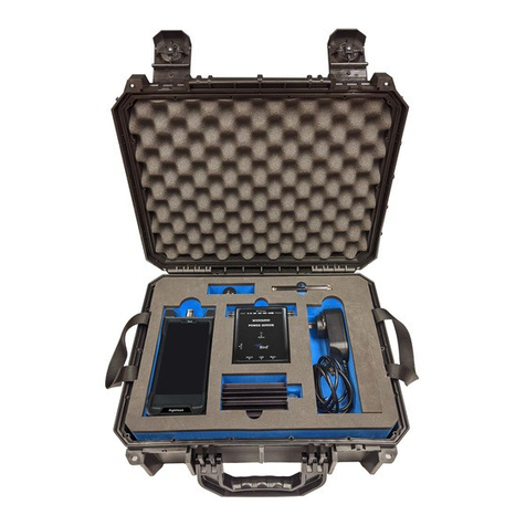
The Bird RF Calibration Kit is meant for operation wherever RF power must be measured at high accuracy and high
power levels. Additionally, the sensors may be used as a standard to calibrate general field power sensors. The RF
Calibration Kit may be used to calibrate RF radios, wattmeters, directional couplers and other high-power RF test
equipment in the field or metrology lab.
Figure 1 RF Calibration Kit
Items Supplied in the SMK-3003, 3% Accuracy RF Calibration Kit
Bird RF Power Meter (P/N 4421A-10-11-0)
AC Power Cord
Sensor Cable
1-10 MHz RF Power Sensor (P/N: SMK-3003-LB)
10-100 MHz RF Power Sensor (P/N: SMK-3003-MB)
100-1000 MHz RF Power Sensor (P/N: SMK-3003-HB)
User Manual

RF Calibration Kit
2
RF Power Sensor Theory of Operation
The precision directional RF Power Sensor contains all necessary components to provide an accurate measurement
of forward and reflected power over the entire specified operating range. They contain the following functional
blocks:
RF measurement — The RF Power Sensor uses directional coupler technology and square-law diode detection to
measure the RF signals. Excellent coupler directivity allows for accurate separation of forward and reflected power.
Square-law detection allows for accurate measurement of true average power for signals of all continuous wave
(CW) modulation types, including complex digital modulation.
Frequency sensing — The RF Power Sensor contains a frequency measurement circuit that enables automatic
correction of measurements based on frequency specific calibration data that is stored in the sensor during factory
calibration.
Microprocessor control — The on-board microprocessor manages all functions of the sensor including data
collection, processing, calibration, and communication to external devices. The microprocessor and other circuitry
are powered from either of the communication interfaces (USB or serial).
Communication interface — The sensor supports two types of communication interfaces for accessing its
power measurements, USB and serial. Connection to the Bird 4421A RF Power Meter is available through the Sensor
Input (serial) interface. The 4421A RF Power Meter provides the simplest means of reading measurements from the
sensor. Connection to a computer is available through the USB interface, which enumerates as a USB-TMC device.
Measurements can be retrieved from the sensor using Standard Commands for Programmable Instruments (SCPI).
Some advanced features are also available through the USB interface, such as modifying the factory calibration.
4421A RF Power Meter
The 4421A RF Power Meter is used to display the measurements of the Bird RF Power Sensors in the RF Calibration
Kit. The 4421A is equipped with a touchscreen interface.
Figure 2 Bird 4421A RF Power Meter Assembly
One Sensor Operation — The 4421A RF Power Meter will display the RF power measurements of one RF Power
Sensor. The sensor may be connected to either of the Sensor connectors, see
"4421A Controls and Indicators"
on page 6
.
Remote Operation — The 4421A’s operation may be controlled from a remote computer/controller and RF
Sensor measurements from the sensor connected to the 4421A may be received on the remote computer. The
remote interfaces include RS-232 and Ethernet.
Note: There are two protocols supported by the 4421A for remote operation, the legacy 4421 protocol
and the new SCPI protocol. Either command protocol may be used to remotely access a single sensor.
Optional Rack Mount Kit
A rack mounting kit is available for the 4421A, see
Appendix 1 on page 29
.

3
Chapter 2 Equipment Description
RF Power Sensor Equipment Description
The RF Power Sensors are used to measure frequencies between 1 and 1000 MHz at power levels between 1 to 1000
Watts. The power sensors are Thruline® directional power sensors that simultaneously measure forward and
reflected power in 50 coaxial transmission lines. Assuming the operating condition of the sensor is within
operating specification limits, then the power sensors are accurate to within ± 3% of reading. An identification label
affixed to the top of the power sensor indicates power range, specified frequency band, and direction of the forward
traveling RF wave.
Display Options
The power sensors may be connected to a Bird 4421A RF Power Meter or a computer.
The Bird 4421A RF Power Meter connects to the sensor using an interface cable that provides a path for serial data
communication between the power sensor and the power meter.
A computer connects to the sensor using the USB Interface. The sensor is controlled using Standard Commands for
Programmable Instruments (SCPI) language. This interface allows a computer to send requests and receive
messages from the sensor without the use of a Power Meter.
Quick-Change Connectors
The RF Power Sensors are equipped with quick-change (QC) type N connectors. The power sensors are shipped from
the factory with one male (input) and one female (output) receptacle connector. However, the QC connectors allow
connectors of other types to be employed.
CAUTION
Only connectors that are in good condition should be used with the RF Power Sensor.
Damaged, worn, or improperly fitting connectors could impact the accuracy of field
RF measurements.

RF Calibration Kit
4
Power Sensor RF / Interface Connectors
The RF Power Sensors have the following connectors.
Figure 3 RF Power Sensor Connectors
Item Name Description
1RF Input Connector RF Power Sensors are supplied with N-type, male, RF input
connectors.
2USB Interface Connector
USB interface connector provides the capability of controlling the
power sensor using Standard Commands for Programmable
Instruments (SCPI) language. This interface allows a computer to send
requests and receive messages from the sensor without the use of a
power meter.
3Sensor Input Interface
Connector
The Sensor Input interface connector is used to connect the sensor to
the 4421A RF Power Meter. The 4421A displays the measurement
data from the RF Power Sensors.
The 4421A also provides the capability of extending the power sensor
operation over an RS-232 data bus.
4RF Output Connector RF Power Sensors are supplied with N-type, female, RF output
connectors.
/RZ)UHTXHQF\
6HQVRU
0LGDQG+LJK
)UHTXHQF\
6HQVRUV

Equipment Description
5
4421A RF Power Meter Equipment Description
The 4421A RF Power Meter is capable of displaying the measurement information from an RF Power Sensor, see
Figure 4
. The measurements maybe be displayed alone, or with an accompanying graph. The display may be
configured to display the following sensor measurements:
Forward Power
Reflected Power
VSWR
Return Loss
Reflection Coefficient
Figure 4 Sensor Measurements Display
6HQVRU0HDVXUHPHQW 6HQVRU0HDVXUHPHQW
ZLWK*UDSK'LVSOD\HG
):'
66HHQQVVRRUU
P:
:
96:5
5)/
$XWR
$XWR
):'
66HHQQVVRRUU
P:
:
96:5
5)/
$XWR
$XWR
VVHHFFRRQQGGVV
$XWR
3RZHU:
&OHDU

RF Calibration Kit
6
4421A Controls and Indicators
Figure 5 Power Meter
Item Indicator Description
1Display/Touch Screen Displays RF Power Sensor information and acts as the user
interface.
2Power Switch
Used to apply and remove power from the unit. Illuminated ring
indicates power is applied to the unit.
• Normal Power ON/OFF - Press and release (short press) the
power button.
• Forced Power Down - Press and hold (long press) the power
button for 3 seconds.
3AC Power Input
Connector
Power input connector (C-14, male), 100-240 VAC, 50-60 Hz,
with integrated fuse holder, requires 1A, 5x20mm, slow-blow
fuses.
4LAN Connector LAN connector provides access to the device’s web UI and
firmware update capability.
5Serial Interface
The RS-232 serial Interface allows computer interface capability
with the 4421A using either the
"4421A SCPI Commands" on
page 18
or the
"Legacy RS-232 Commands" on page 23
.
Either command protocol may be used to remotely access a
single sensor.
6Sensor connectors Two sensor cable connectors. Either connector may be used to
connect an RF Power Sensor.

Equipment Description
7
Display Controls and Indicators
The display is used for presenting information and controlling the behavior of the 4421A. The controls are those
items displayed on the screen, that, when tapped cause a change in the 4421A’s behavior. Controls can be identified
by their color, on screen controls are yellow. The table in
Figure 6
describes the on screen controls and indicators.
Figure 6 Display Controls
Item Indicator Description
1Battery/AC Power
indicator
When connected to AC power, and battery is below 100%, the
charge indicator is displayed.
When connected to AC power and battery is fully charged, a
facsimile of an AC Power Plug is displayed.
When on battery power, the charge level of the battery in
displayed.
2Battery Remaining Indicates the remaining charge of the internal battery.
3Forward and Reflected
Power
The sensor readings for Forward and Reflected power may be displayed
in milliwatts, Watts, Kilowatts, or dBm.
In overrange situations, the 4421A will display the word “RANGE” in
place of the actual power reading.
When Reflected power measurement is dBm, -inf dBm means the
reflected power was 0 W (exactly).
4Measurement Unit The 4421A will display the signal measurements in Watts or dBm.
5Manual Range Controls
Up and Down arrows are used to change the scale of the displayed
power readings.
Note: Stops automatic scaling. Auto indicator (item 7) turns off.
Note: Manual Range not available when measurement unit is dBm.
33RZHU:
):'
66HHQQVVRRUU
P:
:
96:5
5)/
$XWR
$XWR
VVHHFFRRQQGGVV
$XWR &OHDU

RF Calibration Kit
8
6Settings Menu
The settings menu is used to configure what measurement information is
displayed, and to configure LAN and Serial Port settings. See
"Settings
Menu" on page 9
.
7Auto Range
- When button is on, indicates range scale is set to auto.
- When button is off, indicates range scale is in manual control,
see item 5.
Note: Auto Range not available when measurement unit is dBm.
8Limit Lines
Min and max limit lines (green horizontal lines) may be set to display in
the graph’s display area.
The position of the two lines are set in the
"Graph Settings Menu" on
page 10
.
9Clear Tapping Clear discards the graph’s accumulated data and resets time
scale to 60 seconds.
10 Time Scale
The graph’s time scale auto expands as data accumulates with the
following scales:
• 60, 120, 240, 480 seconds
• 15, 30, 60, 120, 240 minutes
• 8, 16, 24 hours
Data accumulation stops at 24 hours.
When graph is turned off then back on the accumulated data is discarded
and time scale resets to 60 second span.
11 Auto Tap Auto to adjust the graph’s power scale to fit accumulated data.
12 Measurement Trace
Forward Power is plotted on the graph in watts on the vertical axis (y)
versus time in the horizontal axis (x). The trace is displayed as a red line.
The graph accumulates data at 1 sample/sec as long as a sensor is
connected.
• If no sensor is connected, accumulation pauses until a sensor is
connected.
• The graph does not account for any gap while a sensor is
disconnected. That is, accumulation will resume as if only 1 second
has elapsed since the last sample.
• The graph does not account for mixing sensors (i.e. switching
sensors in the middle of accumulation).
• Plotted data is either raw data or averaged data. Mode is set in the
power dialog.
13 Power
Power scale defaults to the min/max power specification for a connected
sensor.
The measurement unit will match that selected by the measurement unit
selection (see item 4).
• Power scale may be adjusted automatically (see item 11, Auto) or
via the
"Graph Settings Menu" on page 10
• Tap to open
Graph Settings Menu
.
14
VSWR /
Return Loss/ Reflection
Coefficient
This line on the display can be set to display one of three measurements:
VSWR, Return Loss, or Reflection Coefficient.
The
Settings Menu
is used to select which measurement is displayed.
+inf will be displayed if Reflected power = Forward power (an uncommon
scenario, but could occur with an open circuit).
$XWR
$XWR

Equipment Description
9
Settings Menu
The settings menu is used to select what information will appear on the 4421A’s display as well as configuration of
the LAN and Serial Ports.
Figure 7
describes the options available via the setting menu.
Figure 7 Settings Menu
Item Title Description
1Measurements Check boxes used to select which measurements are displayed for the
attached sensor(s).
2Match Format Radio buttons used to select the format for the match measurement.
3Display Graph When check box is selected, a graph is displayed on the screen with the
associated measurements.
4Use Legacy RS232
When check box is selected, the 4421A will accept the RS-232 command
set used with legacy 4421 power meters. See
Chapter 6, Legacy RS-
232 Commands on page 23
.
5Use Command
Mode
Command mode emulates the command mode dip switch setting from
the legacy 4421 power meter’s RS-232 command set.
6Settings Icon
When tapped, a menu is displayed for selecting the LAN or Serial
configuration menus.
• When LAN is tapped, the 4421A’s IP address configuration menu is
displayed. See
"IP Address Settings Display" on page 11
.
• When Serial is tapped, the 4421A’s serial port settings dialog box is
displayed. See
"Serial Port Setup" on page 12
.
7About
Displays the unit’s Model Number, Serial Number, and Firmware ID.
Compliance and software licensing information may also be viewed from
the About menu.
))RUZDUG
'LVSOD\*UDSK
96:5
5HÀHFWHG
8VH/HJDF\56
6HWWLQJV
$ERXW
8VH&RPPDQG0RGH
5HWXUQ/RVV
0DWFK
5HÀ&RHႇ
L

RF Calibration Kit
10
Graph Settings Menu
The Graph Settings menu is accessed by tapping the power scale on the graph.
Figure 8
describes the options in
the Graph Settings menu.
Figure 8 Graph Settings Menu
Item Title Description
1Range
Text entry boxes for the entry of Min and Max range for the Power Scale
on the Graph. Min and Max values specify the upper and lower limit of
the power scale of the graph.
2Limit Lines
Text entry boxes for the entry of Min and Max value for the limit lines
displayed on the Graph. Two horizontal limit lines may be set to user
specified levels on the power scale. The Min value sets the location of
the lower limit line, while the Max value sets the location of the upper
limit line.
3Average On,
Graphing Mode
Graphing Mode allows the measurement results to be displayed either
raw or averaged. When Average On is checked, each point plotted on the
graph is the arithmetic mean of several raw graph samples.
4Count,
Graphing Mode
Numeric entry for specifying the number of samples used for the moving
average. Applied when Average On is selected.
5Apply When tapped, applies all menu changes and closes the dialog box.
6Cancel When tapped, cancels all menu changes and closes the dialog box.
7Clear Text When tapped, clears all characters in a selected text box.
8Backspace When tapped, while entering a new value in a text box, deletes the
character at the end of the entry. Deletes entire value when highlighted.
9Enter Advances cursor to next text entry box without effecting entered values.
10 Keypad Numerical keypad used to enter values into the various text boxes within
the dialog box.
11 Default When tapped, sets all text entry boxes in the dialog box to default values.
&RXQW
0D[
0LQ
0D[
0LQ .Z
.Z
.Z
.Z
5DQJH
3RZHU&KDQQHO
$YHUDJH2Q
*UDSKLQJ0RGH
/LPLW/LQHV
$SSO\ &DQFHO
'HIDXOW
This manual suits for next models
1
Table of contents
Other BIRD Test Equipment manuals

BIRD
BIRD SignalHawk SH-36S-RM User manual

BIRD
BIRD 4029 User manual

BIRD
BIRD AT-800 User manual

BIRD
BIRD ECONOLOAD 8730 Series User manual

BIRD
BIRD TERMLINE 8141 User manual

BIRD
BIRD AT-500 User manual

BIRD
BIRD AT-400 Antenna Tester AT-400 User manual

BIRD
BIRD FlightHawk User manual

BIRD
BIRD AT-800 User manual
Popular Test Equipment manuals by other brands

Socket & See
Socket & See DIT 400 user guide

Quicktest
Quicktest KEE M-509GM manual

Pro's Kit
Pro's Kit MT-7068 user manual

B+K precision
B+K precision 851 user manual

Kyoritsu Electrical Instruments Works, Ltd.
Kyoritsu Electrical Instruments Works, Ltd. 6011A instruction manual

U.S. General
U.S. General 94190 Assembly and operating instructions