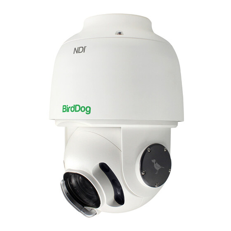
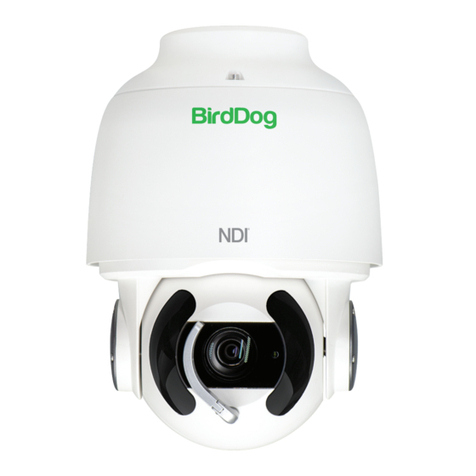
birddog BD-A300 User manual

USER MANUAL
PART 1
FULL NDI®. NO COMPROMISES.
EYES A300

2
Contents
IMPORTANT INFORMATION......................................................................................................................................................................3
WHAT’S IN THE BOX....................................................................................................................................................................................5
OVERVIEW...........................................................................................................................................................................................5
Features..................................................................................................................................................................................................5
Camera Diagrams.........................................................................................................................................................................................6
Installing your Camera.................................................................................................................................................................................7
Power Input....................................................................................................................................................................................................7
PoE Power Injector.......................................................................................................................................................................................8
Mounting the Camera..................................................................................................................................................................................8
Wall Mount.....................................................................................................................................................................................................9
Laser Illuminator............................................................................................................................................................................................9
Use SDI video output...................................................................................................................................................................................10
Starting the Camera.....................................................................................................................................................................................10
Setup Camera ID, Baud Rate and Control Protocol..................................................................................................................................10
Controlling the Camera..............................................................................................................................................................................11
Adjusting and Setting with Menus...........................................................................................................................................................11
EXPOSURE Menu.........................................................................................................................................................................................12
WHITE BALANCE Menu.............................................................................................................................................................................12
PICTURE Menu............................................................................................................................................................................................13
LENS PARAMETERS Menu........................................................................................................................................................................13
SYSTEM SETUP Menu................................................................................................................................................................................14
Video Format...............................................................................................................................................................................................14
FUNCTION SETTING Menu.......................................................................................................................................................................15
Dimensions.....................................................................................................................................................................................................17

3
Operating Instructions
Thank you for purchasing our product. If there are any questions, please contact your authorized dealer.
Before operating the unit, please read this manual thoroughly and retain it for future reference.
Copyright
Copyright 2019 BirdDog Australia all rights reserved. No part of this manual may be copied, reproduced, translated, or distrib-
uted in any form or by any means without prior consent in writing from our company.
Trademark Acknowledgement
and other BirdDog’s trademarks and logos are the property of BirdDog Australia. Other trademarks, company
names and product names contained in this manual are the property of their respective owners.
• Trademarks and Registered Trademark Acknowledgement
• Microsoft, Windows, ActiveX, and Internet Explorer are registered trademarks of Microsoft Corporation in the U.S. and/or
other countries.
• HDMI, the HDMI logo and High-Denition Multimedia Interface are the trademarks or registered trademarks of HDMI Li-
censing, LLC in the United States and other countries.
• Other trademarks, company names and product names contained in this manual are the property of their respective owners.
IMPORTANT INFORMATION
Legal Notice
Attention:
To ensure account security, please change the password after your rst login. You are recommended to set a strong password
(no less than eight characters).
The contents of this document are subject to change without prior notice. Updates will be added to the new version of this
manual. We will readily improve or update the products or procedures described in the manual.
Best effort has been made to verify the integrity and correctness of the contents in this document, but no statement, informa-
tion, or recommendation in this manual shall constitute formal guarantee of any kind, expressed or implied. We shall not be held
responsible for any technical or typographical errors in this manual.
The product appearance shown in this manual is for reference only and may be different from the actual appearance of your
device.
Due to uncertainties such as physical environment, discrepancy may exist between the actual values and reference values pro-
vided in this manual.
Use of this document and the subsequent results shall be entirely on the user’s own responsibility.

4
WARNING!
Installation and removal of the unit and its accesso-
ries must be carried out by qualied personnel. You
must read all of the Safety Instructions supplied with
your equipment before installation and operation.
Warnings:
• If the product does not work properly, please contact your
dealer. Never attempt to disassemble the camera your-
self. (We will not assume any responsibility for problems
caused by unauthorized repair or maintenance.)
• This installation should be made by a qualied service per-
son and should conform to all the local codes.
• When shipping, the camera should be packed in its origi-
nal packaging.
• Make sure the power supply voltage is correct before us-
ing the camera.
• Do not drop the camera or subject it to physical shock.
• Do not touch sensor modules with ngers. If cleaning is
necessary, use a clean cloth with a bit of ethanol and wipe
it gently. If the camera will not be used for an extended
period of time, put on the lens cap to protect the sensor
from dirt.
• Do not aim the camera lens at the strong light such as sun
or incandescent lamp. The strong light can cause fatal
damage to the camera.
• The sensor may be burned out by a laser beam, so when
any laser equipment is being used, make sure that the sur-
face of the sensor not be exposed to the laser beam.
• Mount laser dome camera at a height of six meters (19.7
ft) from the ground. To avoid bodily injury from the laser
radiation, please make sure that no one is within the range
of three meters (9ft) from the camera when the laser is
working.
• Never look at operating laser while the power is on.
• Caution: Use of controls or adjustments to the perfor-
mance or procedures other than those specied herein
may result in hazardous laser emissions.
Maintenance Precautions:
• If there is dust on the front glass surface, remove the dust
gently using an oil-free brush or a rubber dust blowing
ball.
• If there is grease or a dust stain on the front glass surface,
clean the glass surface gently from the center outward us-
ing anti-static gloves or an oil-free cloth. If the grease or
the stain still cannot be removed, use anti-static gloves or
an oil-free cloth dipped with detergent and clean the glass
surface gently until it is removed.
• Do not use organic solvents, such as benzene or ethanol
when cleaning the front glass surface.
Regulatory Compliance
FCC Part 15
This equipment has been tested and found to comply with
the limits for digital device, pursuant to part 15 of the FCC
Rules. These limits are designed to provide reasonable pro-
tection against harmful interference when the equipment is
operated in a commercial environment. This equipment gen-
erates, uses, and can radiate radio frequency energy and,
if not installed and used in accordance with the instruction
manual, may cause harmful interference to radio communi-
cations. Operation of this equipment in a residential area is
likely to cause harmful interference in which case the user will
be required to correct the interference at his own expense.
This product complies with Part 15 of the FCC Rules. Opera-
tion is subject to the following two conditions:
This device may not cause harmful interference.
This device must accept any interference received, including
interference that may cause undesired operation.
LVD/EMC Directive
This product complies with the European Low
Voltage Directive 2006/95/EC and EMC Directive
2004/108/EC.
WEEE Directive–2002/96/EC
The product this manual refers to is covered by the
Waste Electrical & Electronic Equipment (WEEE)
Directive and must be disposed of in a responsible
manner.

5
WHAT’S IN THE BOX
Accessories (Optional)
OVERVIEW
This user guide is suitable for the following models:
BirdDog Eyes A300
Features
• Resolution: Up to 1080P60, 1080i59.94
• NDI®Resolution: Up to 1080P60, 1080P30
• Zoom: Optical 30X
• Video Compression: H.264/MJPEG
• RS485/RS422 Communication, Auto compatible with PEL-
CO D and VISCA Protocol
• Preset store positions and image parameters (iris, white
balance, exposure, picture setting).
• 3D positioning, 120dB true WDR
• Video Output: SDI+IP, True Dual-Output SDI+IP Simulta-
neously
• Intelligent Adaptive IR Illumination up to 100Meters, IR
ON/OFF is available.
• Outdoor Environmental Rating: IP67, Corrosion Resistant
Treatment
• Various Image Functionalities: WDR, BLC, Defog, Day/Night
• Supports ±120°tilt / ±360°pan range, adaptive speed up
to 150°/s
• Supports 255 Presets speed adaptive up 90°/s, 8 Cruises
• Support Zoom Lens Position and Direction Indicator on OSD
• Working temperature: -40°C to 60°C
• Operating Humidity: 80% suitable for use
• Supports Audio input, Audio output with NDI®streaming.
• Input Power: Provides AC24V and POE (BD PoE 80W Injec-
tor needed, optional)
• Firmware upgrade via USB2.0 or IP.
1x BirdDog EyesA300
1x Accessories
1x BD-A300-WM - Wall Mount
1x BD-A300-CM - Ceiling Mount
1x BD-A300-MB - Upright/Ceiling Base
1x BD-A-PMA - Pole Mount
1x BD-A-CMA - Corner Mount
1x BD-A-PP80 - Poe Power Injector 80W

6
Camera Diagrams
Cable Connections
AC Power
Adaptor
24V AC
NDI Video Signal
NDI Control Signal
Alarm Inputs x2
Alarm Output x1
Cat5/6
Network Cable
+
80W PoE
Coaxial Cable
Data Cable Analog Audio Signal
Data Cable Alarm Inputs x2
Data Cable Alarm Output x1
SDI Signal
CAMERA SIDE
CONTROL SIDE
1. IR Laser illuminator
2. Lens
3. Nitrogen Filled Housing Valves
NOTE:
• Nitrogen lled Valves, for factory use only. Do not
open it without consulting your dealer for more infor-
mation.
• All cables are tagged to indicate their functions sep-
arately.
• Use water proof / IP67 rated junction box/ connection
box to protect the RJ45 and other connections.

7
Installing your Camera
The following diagrams are for your reference only. See the
actual product to mount your camera.
Check Camera Components and Installation Conditions.
Before mounting your camera, check the device model num-
ber and included contents against the packing list to ensure
components are complete.
Camera Structure:
1. Tail-Cable
2. Camera Body
Important
• Verify the bearing capacity of the mounted position
• Verify that the mounted position meets the bearing re-
quirements. Otherwise, you are advised to reinforce the
mounted position for the device weight. For more infor-
mation, see the product datasheet.
• Verify lightning protection and grounding requirements
• Select proper lightning protection devices for the power
supply, video signal interfaces, and RS485 interfaces.
• Ground the terminal properly.
Cable Requirements
Network cable
10/100 Mbps Ethernet CAT 5/5E UTP cables are applicable to
the ANSI/EIA/TIA-568A/B and ISO/D. Eight wires in the net-
work cable need to be inserted in parallel into the top of the
cable connector. The cable connector needs to be crimped in
position. When the cable connector is in position, ensure that
the metal pieces of the cable connector are parallel to each
other and the clamp of the cable connector is intact.
SDI Signal Cable
In order to ensure the quality of the installation of the project,
the HD-SDI and 3G-SDI signals have a high data transmission
rate of digital signals, it is necessary to correctly select the
appropriate cable model. In the process of installing a cable,
it should be carefully and carefully, to avoid incorrect to fold,
twist, bend the cable or to apply various kinds of stress to the
cable, so that the signal can be transmitted along the cable
smoothly. Different cable types have different physical char-
acteristics, and the transmission length of the digital signal is
not the same.
Power Input
BirdDog PTZ camera provides 24VAC power input.
Power Cable
Data listed in the below table is applicable to copper cables
that use 24 VAC/24 VDC power supply. The item Core Diam-
eter indicates the conductor diameter.
Power Loss on the Cable for Different Lengths and Differ-
ent Core Diameters
! NOTE: Power supply requirement is 24VAC 2.5 Amp to
ensure proper functionality of PT motor and LED illumina-
tion. Using power supply lower than 24VAC 2.5Amp will
cause camera crashing or insatiability.
Power Connector: Phoenix Connector Description
1. The anode and the cathode are not distinguished for
phoenix connectors of red and black cables.
2. GND: yellow-green color.
Note: GND is used to ground the camera. Ensure that GND
is connected to a reliable grounding point.

8
PoE Power Injector
Other than 24VAC power input, BirdDog PTZ camera pro-
vides PoE power as an optional power input.
For PoE power, you must use BirdDog 80W Power PoE In-
jector: model BL-PP80. It provides high PoE power up to the
PTZ camera. Connect this PoE injector to a network switch
and then run Ethernet cable for data transmission and power
up the PoE PTZ camera (Specic model: A200 & A300) for
distance up to 100 meters.
NOTE!
• Disconnect the power from the camera before
mounting.
• Accessories such as the wall mount bracket and the
pendant mount bracket may be necessary during
mounting. For their model, refer to the accessory list
recommended by your dealer.
• The wall bearing capacity and the bracket length must
meet all onsite mounting requirements. You will need
to select a mount type based the actual environment.
Network Switch
IP Data
PoE 80W
48 VDC
100-240
VAC
24V
AC
PoE
Power
Injector
Power
supply
Mounting the camera
NOTE!
• When mounting the camera, please install the bracket
adapter to the bracket rst and then mount the camera
to the bracket.
• Tighten all the screws to hold the camera securely.
• For waterproong, apply sealant between the dome
and the bracket, wall veneer slits, and leading-out
holes of the wall.
Wall Mount Pedant or Up-Right.
•

9
Laser Illuminator
Adaptive IR Laser Illuminator
The A300 camera uses adaptive IR laser illuminator to provide
up to 1000 ft /1500 ft of long range illumination. IR laser uses
diffused illumination that provide the long distance visibility.
Precaution & Specs:
1. This product uses Class 3B laser light product.
2. Supports Manual / Auto IR laser control
3. Uses synchronous zoom with continuously adjustable il-
lumination angle of 68 ° ~ 2 °.
4. Supports intelligent light-adjustment which automati-
cally adjust the power of infrared laser light and avoids
reective object and close range image overexposure.
5. Mount a laser dome camera at a height of six (6) meters
(19.7 ft) from the ground. To avoid bodily injury from the
laser radiation, please make sure that no one is within the
range of three (3) meters (9 ft) from the camera when the
laser is working.
6. When the IR laser is operating, do not look directly into
the laser beam or obstruct the pathway of the beam.
7. Everyone who uses a laser should be aware of the risks
and take necessary caution when handling, operating
and maintaining the product.
Wall Mount
1. Open the bracket cover, mount it onto the wall or pole
(use pole adaptor).
2. Put on 3 screws onto the bottom of the camera, leave
enough space to t in the screw holes on the bracket,
not to screw tight.
3. Hold up the camera close under the bracket, insert the
tail-cable of the camera into the chest of the bracket.
4. Insert the 3 screws into the screw holes and turn the
camera counterclock wise so that the camera can be held
by the camera. Screw up the 3 screws but not too tight.
5. Put on the 4th screw and screw in tightly. Screw in the
rest of the screws tightly.
6. Finish the cable connection. Put all cable and connectors
inside of the bracket.
7. Put the cover back to the bracket and screw in securely.

10
Use SDI video output
Starting the Camera
After you have mounted the camera properly, connect the
camera to power.
Each time the camera is powered on, it will perform a self-
test to check the Pan/Tilt/Zoom (PTZ function). After self-
test, you can operate the camera.
NOTE!
• The self-test process starts after the camera is pow-
ered up. Please wait patiently.
• When the operating temperature is lower than zero
degrees Celsius, the camera will be automatically pre-
heat (the pre-heat process takes 30 minutes at most).
The self-test starts only after the temperature rises
above zero degrees Celsius.
Connect Camera to Monitor/SDI Device
To view your camera, you need to use the coaxial cable to
connect your camera to monitor or SDI device.
* The monitor/device must support the signal of HD-SDI or
3G-SDI.
Connect Camera with Controller
To control and congure your camera, you need to connect
with control system (or control keyboard) for communication
by RS-485/RS422. Set up the protocol of communication by
control keyboard, the camera can auto detect VISCA and
PELCO-D.
1. Connection
1.1 RS485 (PELCO D) control connection diagram
Connect the Camera’s RS485+ and RS485 to RS485/TX+ and
RS485/TX- on the control system/keyboard. The identity of
the control system or equipment may be different; the corre-
sponding relationship is as follows:
Camera
(RS485)
1. RX +
2. RX –
Keyboard
(PELCO P/D)
6. TX+
7. TX –
RS485 (PELCO D)
Multiple Cameras Connection
RX +RX –
RX +RX –
RX +RX –
RX +RX –
CAM1SYSTEM /
KEYBOARD
(PELCO D)
CAM 2
CAM 3
CAM 255
RS485 PELCO D
System / Keyboard
Connection
TX –
TX +
RX +RS 485 A RS 485 +RS 485 D+
RX –RS 485 B RS 485 –RS 485 D–
1.2 RS422 (VISCA) control connection diagram
• SONY Keyboard RS422 Connection
• VISCA (None-Sony) Keyboard RS422 Connection
Setup Camera ID, Baud Rate and
Control Protocol
In order for you to control a camera, the camera ID, baud rate
and control protocol have to be set up in advance, Baud rate
and the camera ID setting on the camera have to be the same
as baud rate and camera ID setting on the system/control
keyboard. The camera can auto detect the VISCA and PEL-
CO-D, only need to set up the camera address and baud rate.
Connect the camera to a monitor. There is an initial setting
page displaying on the screen for 5 seconds when the cam-
era is powered on. On the page, it shows the factory default
setting of the camera ID, baud rate and other information.
Suggest taking a picture of this default setting information
for setting keyboard use. Set the keyboard or control system
to match the camera ID, baud rate setting with the camera.
1. Camera supports VISCA and PELCO-D protocols, proto-
col is detected automatically by the camera.
2. Factory Default Setting: For both SDI and IP video, Baud
Rate: 9600, Camera ID: 001, Pelco Protocol.
Camera
(RS422)
4. TX +
3. TX –
2. RX +
1. RX –
Keyboard
1. ---
2. ---
3. ---
4. ---
5. GND
6. RXD IN –
7. RXD IN +
8. TXD IN –
9. TXD IN +
RS422 (VISCA)
Multiple Cameras Connection
(SONY Keyboard)
RX +RX – TX +TX – GND
RX +RX –T X +TX – GND
KEYBOARD
CAM 1
CAM 2
CAM 7
SONY Keyboard
RS422 Connection
Camera
(RS422)
4. TX +
3. TX –
2. RX +
1. RX –
Keyboard
1. GND
2. RXD IN –
3. RXD IN +
4. TXD IN –
5. TXD IN +
RS422 (VISCA)
Multiple Cameras Connection
(VISCA Keyboard)
RX +RX –T X +TX – GND
KEYBOARD
CAM 1
CAM 2
CAM 7
VISCA Keyboard
Connection

11
3. Use RS485 Pelco-D can control up to 255 cameras, cam-
era ID from 001 to 255 has to be set.
4. Use RS422 VISCA protocol can control up to 7 cameras,
camera ID from 1 to 7 has to be set.
5. Supports baud rate of 2400bps, 4800bps, 9600bps and
38400bps.
6. How to set up the address and baud rate of the camera
for SDI, please see the Page18.
7. On the keyboard side, for RS485 control, go into the
camera setting menu, select the camera address/ID you
want to set up for, set the baud rate to match the same
as the one has been set on camera side, select protocol
Pelco D for RS485 control. (How to set up the menu of
the keyboard, please refer to the instruction of the key-
board you are using.)
8. On the keyboard side, for VISCA control, select RS232/
RS422 control method, set the baud rate to match the
same as the one has been set on camera side. (How to
set up the VISCA keyboard, please refer to the instruc-
tion of the keyboard you are using.)
9. On IP control side, go into the camera IP web interface
setting page by using browser to login camera IP ad-
dress (Default set to 192.168.0.13), go to “Setup→Sys-
tem→Port&Devices” setting page, set the Baud Rate,
camera ID, Protocol to the same as the ones that have
been set on the camera side.
10. SDI and IP video setting have to be matching with each
other, if you change any one of the settings on any sides
of the SDI or IP.
NOTE!
• Regarding the camera ID and Baud Rate setting, for the
rst communication setting, you must match the control
system (or keyboard) camera ID and Baud Rate setting
to the cameras.
PTZ Control
1
8
9600
None
None
1
PELCO-D
Port Mode
Stop Bits
Data Bits
Baud Rate
Flow Control
Parity
Address Code
PTZ Protocol
Enable Trans-Channel
RS485_1
• After communicating successfully in between the cam-
era and the control, you can modify the ID and baud rate
of the camera using the keyboard.
• By default, the camera Baud Rate.
Controlling the Camera
The operation of the control systems or devices of different
makers may be different. To operate the camera, please refer
to the manual of the control system or the device.
Adjusting and Setting with Menus
About On-Screen Menus
You can change various settings, such as shooting conditions
and system setup of the camera, while observing menus
displayed on a connected computer screen. This section ex-
plains how to read the on-screen menus before starting menu
operations.
The menu parameters may vary according to the different
product model numbers. For a complete congurations
menu, see “Menu Conguration” .
NOTE: You cannot perform pan/tilt operations while the
menu is displayed.
Run preset 95th using keyboard to call/display
the On-Screen Menu, the main menu will display
on the screen.
How to run presets of cameras, please refer to the manual of
the keyboard/control system that you are using.
How to adjusting and setting by joystick of keyboard
1. Push the joystick of the keyboard to the up or down: To
select the menu that you want.
2. Push the joystick of the keyboard to the right: To enter
the menu that you want.
3. Push the joystick of the keyboard to the right: To conrm
the value that you want to set to.

12
EXPOSURE Menu
The EXPOSURE menu is used to set the items related to ex-
posure. AE MODE (Exposure Mode)
FULL AUTO: The exposure is adjusted automatically using
the sensitivity, electronic shutter speed, and iris.
BRIGHT: Adjust the brightness level (LEVEL) manually.
SHUTTER: Shutter mode. The exposure is adjusted automat-
ically using the sensitivity and iris. Adjust the electronic shut-
ter speed (SPEED) manually.
IRIS PRI: Iris Priority mode. The exposure is adjusted auto-
matically using the sensitivity and electronic shutter speed.
Adjust the iris (IRIS) manually.
MANUAL: Adjust the sensitivity (GAIN), electronic shutter
speed (SPEED) and iris (IRIS) manually.
When you select one from various exposure modes, some of
the following setting items that are required for the selected
mode appear.
GAIN: Select the gain from the following: -3, 0, 3, 9, 15, 18 dB
SPEED: Select the electronic shutter speed from the fol-
lowing: 1/1, 1/2, 1/3, 1/6, 1/12, 1/25, 1/50, 1/75, 1/100,
1/120, 1/150, 1/215, 1/300, 1/425, 1/600, 1/1000, 1/1250,
1/1750, 1/2500, 1/3500, 1/6000, 1/10000 sec.
IRIS: Select the iris the following: CLOSE, F14, F11, F9.6,
F8.0, F6.8, F5.6, F4.8, F4.0, F3.4, F2.8, F2.4, F2.0, F1.6
LEVEL: Select the brightness level from 0 to 23.
BACKLIGHT MODE: When the background of the subject is
too bright, or when the subject is too dark due to shooting in
the AE mode, back light compensation will make the subject
appear clearer. This is set to ON, OFF.
WIDE-D (Wide dynamic range mode): ON, OFF. The cam-
era distinguishes light and dark areas within the same scene,
adjusts the brightness for dark areas, and also controls the
blown out highlights.
DEFOG: ON, OFF. If the shooting scene has fog, you can open
the defog function to improve the penetration of the image.
AUTO SLOW SHUTTER: ON, OFF. When AUTO SLOW SHUT-
TER is set to on, it can auto adjust the electronic shutter
speed.
EX-COMP (Exposure Compensation): When MODE is set to
one of FULL AUTO, SHUTTER PRI or IRIS PRI, set this item
to ON to enable exposure compensation. When you set EX-
COMP to ON, LEVEL appears and you can select the expo-
sure compensation level from the following: -10.5, -9, -7.5, -6,
-4.5, -3, -1.5, 0, +1.5, +3, +4.5, +6, +7.5, +9, +10.5
If you set the level to 0, exposure compensation will be dis-
abled. Level +10.5 is the brightest and –10.5 is the darkest
compensation value. When EX-COMP is set to OFF, exposure
compensation does not function.
EXIT: Push the joystick to the right to exit this level menu.
WHITE BALANCE Menu
The WHITE BALANCE menu is used to select the white bal-
ance mode.
MODE (white balance mode):
Select the white balance mode from the following:
AUTO, IN DOOR, OUT DOOR, ATW (Auto Tracing White
Balance), OPW (One Push White Balance), USER, OUTDOOR
AUTO, SLA (Sodium Lamp Auto), SL (Sodium Lamp), SLOA
(Sodium Lamp Outdoor Auto).
When you select USER, R. GAIN (red gain) and B. GAIN (blue
gain) appear. You can select each item in the range from 0 to
255.
EXIT: Push the joystick to the right to exit this level menu.

13
PICTURE Menu
The PICTURE menu is used to set the items related to the
picture.
OSD
EXPOSURE
WHITE BALANCE
PICTURE
LENS PARAMETERS
SYSTEM SETUP
FUNCTION SETTING
SAVE AND EXIT
EXIT
PICTURE MENU
APERTURE
EFFECT
COLOR GAIN
COLOR HUE
EXIT
8
OFF
3
7
APERTURE: The aperture is used to adjust the picture edge
sharpness. The value of the aperture is high, the edge of the
picture more clearly, the value is low, more blurred. Select
the aperture from the following: 0 - 15.
EFFECT: (Picture Effect)
It consists of the following functions:
Neg. Art: Negative/Positive Reversal
Black & White: Monochrome Image
Image effect from Off, B&W, NEG.ART
COLOR GAIN: 3 (Value :0~14)
COLOR HUE: 7 (Value: 0~14)
EXIT: Push the joystick to the right to exit this level menu.
LENS PARAMETERS Menu
The LENS PARAMETERS menu is used to set the items relat-
ed to the lens.
OSD
EXPOSURE
WHITE BALANCE
PICTURE
LENS PARAMETERS
SYSTEM SETUP
FUNCTION SETTING
SAVE AND EXIT
EXIT
LENS PARAMETERS MENU
DIGITAL ZOOM
JOYSTICK RECOVER
A/F RECOVER TIME
A/I RECOVER TIME
FOCUS NEAR LIMIT
DAY/NITE MODE
LASER
GAMMA
ZOOMING SPEED
PRESET SPEED
EXIT
OFF
NONE
000
000
30CM
NIGHT
ON
NORMAL
8
255
DIGITAL ZOOM: ON, OFF. When DIGITAL ZOOM is set to
on, it can use the digital zoom.
JOYSTICK RECOVER:
NONE: No effect.
A/F: After operate the camera, the mode of focus be
changed to auto form manual.
A/I: After operate the camera, the mode of IRIS be
changed to auto form manual.
AF-AI: After operate the camera, the mode of focus be
changed to auto form manual, and, the mode of IRIS be
changed to auto form manual.
A/F RECOVER TIME: When the camera is not in operation, if
in the manual focus mode, after the A/F RECOVER TIME, it
will automatically transfer to the automatic focus. If the time
is 0, then the function is closed.
A/I RECOVER TIME: When the camera is not in operation, if
in the manual Iris mode, after the A/I RECOVER TIME, it will
automatically transfer to the automatic Iris. If the time is 0,
then the function is closed.
FOCUS NEAR LIMIT: The near limit from the following: 1cm,
11cm, 30cm, 0.8m, 1.2m, 1.4m, 1.65m, 2.0m, 2.5m, 3.1m,
4.2m, 6.0m, 10m, 20m.
DAY/NITE MODE: You can select the mode from AUTO, DAY
and NIGHT.
When the camera is set to AUTO mode, the camera
will automatically turn from Day mode (Color) to Night
mode (Black & White) when the lighting condition is low
enough, the camera illuminator will be turned on auto-
matically at Night mode.
When the camera is set to Day mode, the camera will
stay in Day mode (Color) no matter how low the lighting
condition is, the camera illuminator will not be turned on
at Night. The image may be too dark to be seen in a low
light condition.
When the camera is set to Night mode, the camera will stay
in Night mode (Black & White) no matter how bright the
lighting condition is, the camera illuminator will be turned
on all the time. The image will be stay in Black & White.
LASER: ON/OFF. You can turn the Laser OFF when you don’t
need the illumination at all. When you turn the Laser ON, the
illumination can be set to Day/Nite modes.
GAMMA: The gamma can be set to Auto, Manual, and value
from 0 to 4.
ZOOMING SPEED: The speed of zooming can be set to value
from 1 to 8.
PRESET SPEED: The speed of preset can be set to value from
1 to 255.
EXIT: Push the joystick to the right to exit this level menu.

14
SYSTEM SETUP Menu
The SYSTEM SETUP menu is used to set the items related to
the camera system.
OSD
EXPOSURE
WHITE BALANCE
PICTURE
LENS PARAMETERS
SYSTEM SETUP
FUNCTION SETTING
SAVE AND EXIT
EXIT
SYSTEM SETUP MENU
FACTORY DEFAULT
DISPLAY CONFIG.
INTERFACE SET
FLIP
SDI VIDEO
PAN DIRECTION
TILT DIRECTION
PROPORTIONAL PT
SET NORTH
SYSTEM INFO
SYSTEM RESET
OFF
1080P30
NORMAL
NORMAL
ON
FACTORY DEFAULT: The menu is used to restore the factory
settings.
DISPLAY CONFIGURATION: Entered the menu of DISPLAY
CONFIGURATION, it will be shown the below items:
ZOOM LENS POSITION: Select ON to display the zoom
lens position on the screen.
DIRECTION INDICATOR: Select ON to display the direc-
tion indicator on the screen.
INTERFACE SET: This menu is used to set the following:
CAMERA ID: Factory Default Setting: 001. Use RS485 Pel-
co-D can control up to 255 cameras, camera ID from 001
to 255 has to be set. Use RS422 VISCA protocol can con-
trol up to 7 cameras, camera ID from 1 to 7 has to be set.
BAUD RATE: Factory Default Setting: 9600. Select
the baud rate from the following: 2400, 4800, 9600,
38400bps.
FACTORY FORMAT: Set factory default format.
NOTE!
• After the camera ID and Baud rate is set, to activate
the new set camera ID and Baud rate, the camera has
to be rebooted by powering the camera OFF and ON.
• For Dual-Output camera, the camera ID and Baud rate
on IP web interface has to be set to the same ID as the
camera’s for IP control.
• You may need to reboot the keyboard after you change
the camera ID and Baud rate.
• Once modied and saved the camera ID and baud rate,
please modify the corresponding parameters on both
the keyboard and IP web interface setting, otherwise
the camera and keyboard and IP control will be unable
to communicate.
FLIP: Select ON to ip the image if you need to lift the camera.
VIDEO FORMAT: SDI + IP True Dual Output: You can have
parallel SDI and IP video output. Either SDI or IP video format
can be set up independently for having dual output simulta-
neously.
• SDI output: Select the SDI video output format from the
following: 1080p 60, 59.94, 50, 29.97, 25; 1080i 60, 59.94,
50; 720p 60, 59.94, 50, 29.97, 25
• IP output: Select the IP video output format from the fol-
lowing: 1080P:30/25, 720P:30/25
Follow the steps to change the video format:
1. Set SDI video resolution in SYSTEM SETUP.
2. Select the SDI VIDEO format you want to have.
3. Waiting for a while for camera new set video format be-
ing taken. It is normal that you cannot take the control of
the interface while the video format is being changed.
You can reboot the camera by powering OFF and ON
to active the new set video format if it takes too long to
complete the format changing by itself.
4. Go to IP camera Web Interface), you can set IP video res-
olution.
PAN DIRECTION: NORMAL/INVERT. Supports normal and
inverted directions on Pan movement.
TILT DIRECTION: NORMAL/INVERT. Supports normal and
inverted directions on Tilt movement.
PROPORTIONAL PT: Turn ON to automatically adjust the
Pan and Tilt speed with various zoom ratios. For example,
the higher zoom ratio you use, the slower the speed of P/T.
Turn OFF to inactivate the feature to set the at speed of Pan
and Tilt.
SET NORTH: Select ON to open this function. Turn the cam-
era to the north, and then save it by call preset 1.
SYSTEM INFO: CAMERA ID, BAUD RATE, SDI VIDEO, IP VID-
EO: Modify in the menu of “INTERFACE SET”.
VERSION: The version of the software.
SYSTEM RESET: To save the changes have been made and
make the changes activated.
EXIT: Push the joystick to the right to exit this level menu.

15
FUNCTION SETTING Menu
The FUNCTION SETTING menu is used to set the items relat-
ed to the camera functionalities.
OSD
EXPOSURE
WHITE BALANCE
PICTURE
LENS PARAMETERS
SYSTEM SETUP
FUNCTION SETTING
SAVE AND EXIT
EXIT
FUNCTION SETTING MENU
PRESET SETUP
TOUR SETUP
PATTERN SETUP
SCAN SETUP
IDLE TIMER
IDLE ACTION
EXIT
003
OFF
Note: The number of available presets may be limited by
the head-ins, controllers, and DVRs that are connected to
your dome system.
PRESETS SETUP: Preset is to store the PTZ information (such
as: Pan and Tilt positions, focal length etc.) under the specic
condition, and call the camera PTZ quickly to shoot to the
specied location that you want the camera to move to.
Note: Presets not only save desired image positions, var-
ious picture settings such as brightness, exposure val-
ues, white balance and other variables are also saved and
stored.
This function allows you to achieve the desired status instant-
ly, even without adjusting the following items each time.
Pan/Tilt Position, Zoom Position, Digital Zoom On/Off,
Focus Auto/Manual, Focus Position, AE Mode, Shutter
control parameters, Bright Control, Iris control parame-
ters, Gain control parameters, Exposure Compensation
On/Off, Exposure Level, Backlight Compensation On/
Off, White Balance Mode, R/B Gain, Aperture Control,
WD Parameter.
The menu is used to manage the presets.
PRESETS NUMBER: The current preset number that you are
managing.
PRESET MEMORY: ON/OFF When this feature is set to ON,
All presets store camera positions and image parameters.
When this feature is set to OFF, 1-16 presets still store camera
positions and image parameters, but 17-128 presets will only
store camera positions. You can set the presets to number
17-128 if you don’t want the preset to memorize the image
parameter settings.
SET NEW PRESET: To set up the preset of the above preset
number.
1. Push the joystick to the right to enter this setting menu,
you will see “call preset 1 to end”.
2. Adjust the camera to the position that you want the cam-
era to be, and then call the preset 1 using the keyboard
to save the position to be the current preset.
3. Finished.
DELETE PRESET: Delete the above preset.
1. Push the joystick to the right to delete this preset.
2. Finished.
EXIT: Push the joystick to the right to exit this level menu.
In order to use the special functions of the camera, the fol-
lowing presets are predened for specic functions (You can
nd the default predened preset at Web interface, Setup →
PTZ →Advanced Settings):
SYSTEM SETUP MENU
LENS RESET
OPEN BACKLIGHT
CLOSE BACKLIGHT
OPEN AUTO SHUTTER
CLOSE AUTO SHUTTER
OPEN SCREEN DISPLAY
CLOSE SCREEN DISPLAY
OPEN DIGITAL ZOOM
CLOSE DIGITAL ZOOM
DISABLE WDR
ENABLE WDR
AUTO IRIS
MANUAL IRIS
AUTO WHITE BALANCE
MANUAL WHITE BALANCE
IMAGE NORMAL
IMAGE FLIP
COLOR MODE
BLACK AND WHITE MODE
AUTO DAY/NIGHT MODE
OPEN MENU
START PATROL
SET PATROL ROUTE
AUTO FOCUS
MANUAL FOCUS
OSD
SET
CALL
SET
CALL
SET
CALL
SET
CALL
SET
CALL
SET
CALL
SET
CALL
SET
CALL
SET
CALL
SET
CALL
SET
CALL
SET
CALL
SET
OSD
54
55
56
57
58
59
60
61
63
64
65
95
97
99
TOUR SETUP: The menu is used to manage the tours. Total of
4 tours can be managed.
SEQUENCE NUMBER: The current tour number that you
are managing.
DEFAULT DWELL: Set the interval time between each of
presets in the above tour, the value can be selected from
3 to 255 sec.

16
EDIT SEQUENCE: Set up the above tour.
1. In the order of 1, 2, 3, ... , 6, add each of preset and
default dwell time to the tour.
2. The tour path will be set based on the presets and
default dwell have been set in step one.
RUN CONTINOUSELY: start the tour has been set.
EXIT: Push the joystick to the right to exit this level menu.
PATTERN SETUP: A pattern is a memorized, repeating series
of pan, tilt, zoom, and preset functions that can be recalled
with a command from a controller or automatically by a pro-
grammed function (alarm, park, event, or power-up).
The menu is used to manage the patterns. Total of 4 patterns
can be managed.
PATTERN NUMBER: The current pattern number that
you are managing.
RECORD NEW PATTERN: Set up the above pattern.
1. Push the joystick to the right to enter this setting menu.
2. Move the camera to the start position you want, and
then call the preset 1 to save.
3. Move the camera to each position you want to record
the pattern, and then call the preset1 to end.
4. Finished.
RUN CONTINIUSELY: start the above pattern.
EXIT: Push the joystick to the right to exit this level menu.
SCAN SETUP: The menu is used to manage the scans. Total
of 4 scans can be manage.
PANNING NUMBER: The current scan number that you
are managing.
SET LEFT LIMET: Set the left limit of the camera scan.
1. Push the joystick to the right to enter this setting menu.
PRESET
NUMBER
000
000
000
000
...
DEFAULT
DWELL
000
000
000
000
...
PRESET
NUMBER
000
000
000
000
...
DEFAULT
DWELL
000
000
000
000
...
PRESET
NUMBER
000
000
000
000
...
DEFAULT
DWELL
000
000
000
000
...
2. Move the camera to the left limit position that you
want, and then call the preset 1 to save.
SET RIGHT LIMET: Set the right limit of the camera scan.
1. Push the joystick to the right to enter this setting menu.
2. Move the camera to the right limit position that you
want, and then call the preset 1 to save.
DEFAULT SPEED: Set the interval time from left to right
during Scanning, and select value from 3 to 255 sec.
RUN CONTINOUSELY: start the above scan.
EXIT: Push the joystick to the right to exit this level menu.
IDLE TIMER: If the camera stays in No-operation for certain
amount of IDLE Time, the camera would take action auto-
matically.
The menu is used to set the IDLE time, and value can be se-
lected from 0 to 255 sec.
IDLE ACTION: After the IDLE time, the camera starts the
IDLE action automatically.
Even if the idle time’s value is set to 0, or during the IDLE
time, manual operation will always have the priority to the
response.
The menu is used to select the IDLE action.
The IDLE action can be selected from: OFF, PRESET1-220,
SCAN1-4, TOUR1-4, PATT1-4.
EXIT: Push the joystick to the right to exit this level menu.
EXIT
Push the joystick to the right to exit the menu. All the setting
modications will be saved.

WELCOME TO THE FUTURE.
bird-dog.tv
hello@bi rd-dog.tv
This manual suits for next models
1
Table of contents
Other birddog Security Camera manuals

birddog
birddog Eyes P400 User manual

birddog
birddog BDP240B User manual

birddog
birddog EYES P200 User manual

birddog
birddog NDI P200 User manual

birddog
birddog BDA200 User manual

birddog
birddog P120 User manual

birddog
birddog BDP100B User manual

birddog
birddog EYES A200 User manual

birddog
birddog BDP200B User manual

birddog
birddog EYES A200 User manual