BIS VISTA User manual

BIS VISTA™Monitoring System
OPERATING MANUAL
Rx only
EC REP
Aspect Medical Systems, Inc. Aspect Medical Systems International B.V.
One Upland Road Rijnzathe 7d2
Norwood, MA 02062 3454 PV De Meern
U.S.A. The Netherlands 0123
(Tel) 617-559-7000 Tel: +31.30.662.9140
(Tel) 888-BIS INDE(X) (U.S. only) Fax: +31.30.662.9150
www.aspectmedical.com
070-0069 3.00


BIS VISTA™Monitoring System
OPERATING MANUAL
©Copyright, 2008, Aspect Medical Systems, Inc. All rights reserved. Copying or other
reproduction of this document is prohibited without prior written consent of Aspect
Medical Systems, Inc.
BIS VISTA is a trademark of Aspect Medical Systems, Inc.
Aspect, Bispectral Index, BIS, the BIS logo, BISx, the BISx logo and Zipprep are trademarks
of Aspect Medical Systems, Inc. and are registered in the U.S.A., E.U. and other countries.


TABLE OF CONTENTS
ABOUT THIS MANUAL........................................................................................ i
INTRODUCING THE BIS VISTA MONITORING SYSTEM............................ ii
1SAFETY PRECAUTIONS........................................................................... 1-1
1.1 Warnings....................................................................................................................... 1-1
1.2 Cautions........................................................................................................................1-3
1.3 Key to Symbols ............................................................................................................ 1-6
2INSTALLATION AND PREPARATION FOR USE ................................ 2-1
2.1 BIS VISTA Monitor Installation and Checkout ........................................................ 2-1
2.2 Environment................................................................................................................. 2-2
2.2.1 Shipping and Storage Environment....................................................................................................... 2-2
2.2.2 Operating Environment .......................................................................................................................... 2-2
2.2.3 Power Requirements and System Grounding.................................................................................... 2-3
2.2.4 Electromagnetic Compatibility Requirements.................................................................................... 2-3
2.2.5 Site Preparation: Mounting the Monitor ............................................................................................. 2-4
2.2.5.1 Mounting the Monitor using the Pole Clamp .......................................................................... 2-4
2.2.5.2 Optional Mounting Accessories................................................................................................. 2-5
2.3 The BIS VISTA Monitoring System – Equipment and Supplies ............................. 2-6
2.3.1 BIS VISTA Monitor .................................................................................................................................. 2-7
2.3.1.1 Front Panel...................................................................................................................................... 2-7
2.3.1.2 Touch Screen ................................................................................................................................. 2-7
2.3.1.3 ON/Standby button ...................................................................................................................... 2-7
2.3.1.4 Rear Panel....................................................................................................................................... 2-7
2.3.1.5 Integral Battery .............................................................................................................................. 2-9
2.3.2 BISx ........................................................................................................................................................... 2-10
2.3.3 Patient Interface Cable (PIC)............................................................................................................... 2-11
2.3.4 BIS Sensors .............................................................................................................................................. 2-11
2.4 Cable Connections..................................................................................................... 2-11
2.5 Start Procedure / Standby Mode ............................................................................. 2-12
2.5.1 Starting the Monitor for the First Time ............................................................................................ 2-12
2.5.2 Starting the Monitor from Standby Mode......................................................................................... 2-12
2.6 Initial Menu Settings.................................................................................................. 2-12
2.6.1 Language Selection................................................................................................................................. 2-13
2.6.2 Date and Time........................................................................................................................................ 2-13
2.6.3 View/Save Settings.................................................................................................................................. 2-13

3OPERATING THE BIS VISTA MONITORING SYSTEM....................... 3-1
3.1 Preparing for Operation ............................................................................................. 3-1
3.2 Sensor Check................................................................................................................ 3-3
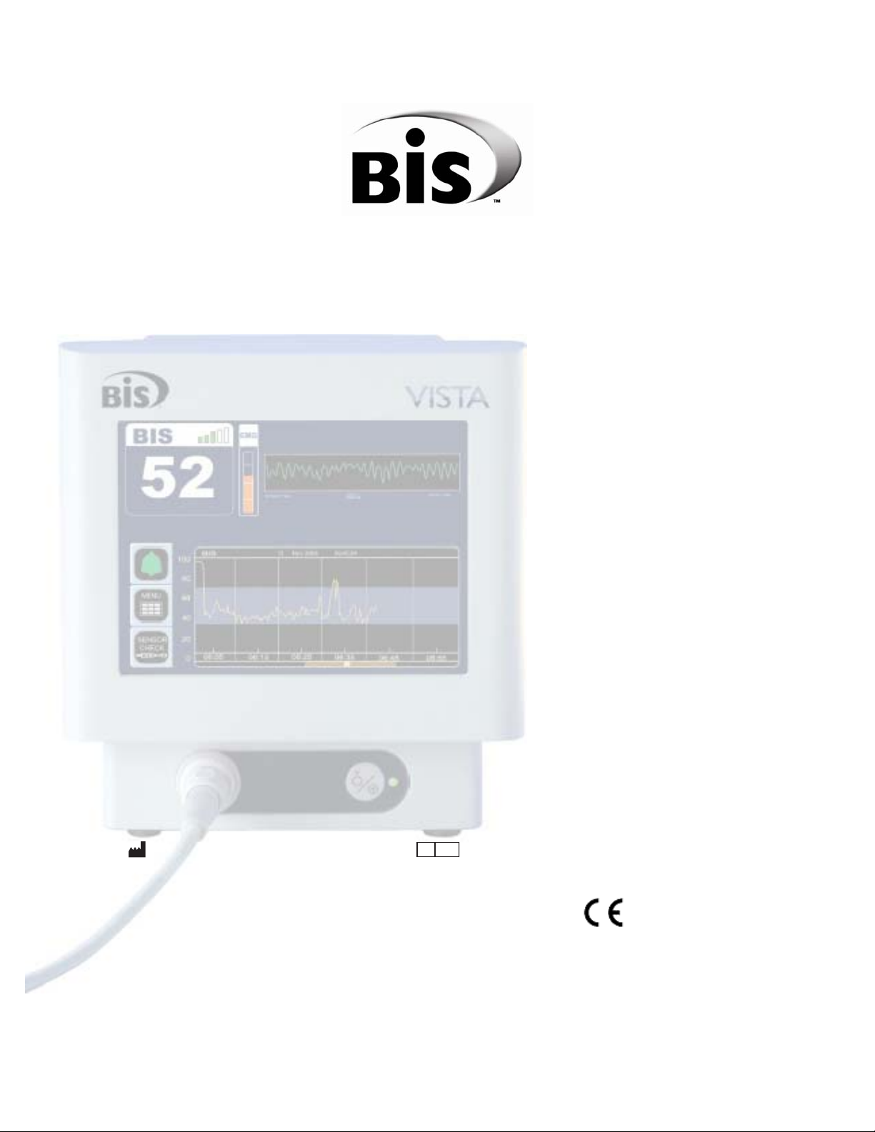
3.3 BIS Trend Data Screen ............................................................................................... 3-6
3.3.1 BIS (Bispectral Index) Value................................................................................................................... 3-6
3.3.2 Signal Quality Indicator........................................................................................................................... 3-6
3.3.3 Electromyograph (EMG) Indicator ....................................................................................................... 3-7
3.3.4 EEG Waveform Display .......................................................................................................................... 3-7
3.3.5 Message Region ........................................................................................................................................ 3-7
3.3.6 BIS Trend Graph ...................................................................................................................................... 3-8
3.3.7 Additional Screen Information .............................................................................................................. 3-9
3.3.7.1 Battery Icon.................................................................................................................................... 3-9
3.3.7.2 USB Export Icon............................................................................................................................ 3-9
3.3.7.3 Print Icon....................................................................................................................................... 3-10
3.3.7.4 Extend Mode ................................................................................................................................ 3-10
3.3.7.5 Suppression Ratio (SR) Number .............................................................................................. 3-10
3.3.7.6 Burst Count (Bursts/Minute) .................................................................................................... 3-10
3.4 Main Screen Touch Keys........................................................................................... 3-11
3.4.1 Alarm Touch Keys ................................................................................................................................. 3-11
3.4.2 Menu, Home, Sensor Check and Review Touch Keys................................................................... 3-12
3.5 Menu Selections ......................................................................................................... 3-13
3.5.1 Target Range ........................................................................................................................................... 3-13
3.5.2 Secondary Variable ................................................................................................................................ 3-15
3.5.3 Chart Data............................................................................................................................................... 3-16
3.5.4 Alarm Volume......................................................................................................................................... 3-17
3.5.5 BIS/EEG Display Modes......................................................................................................................... 3-18
3.5.6 View/Save Settings.................................................................................................................................. 3-18
3.5.7 Help........................................................................................................................................................... 3-19
3.5.8 Snapshot................................................................................................................................................... 3-20
3.5.9 Display Suppression Ratio (SR)........................................................................................................... 3-20
3.5.10 Monitor Mode ................................................................................................................................... 3-21
3.5.11 Export Data ....................................................................................................................................... 3-22
3.5.12 BIS Smoothing Rate.......................................................................................................................... 3-24
3.5.13 Print (Snapshot)................................................................................................................................. 3-25
3.5.14 Configuration Information .............................................................................................................. 3-26
3.5.15 EEG Channels.................................................................................................................................... 3-26
3.5.16 Date and Time................................................................................................................................... 3-27
3.5.17 Language ............................................................................................................................................. 3-28
3.5.18 Filters................................................................................................................................................... 3-28
3.5.19 Impedance Checking ........................................................................................................................ 3-29
3.5.20 Maintenance Menu............................................................................................................................ 3-30
3.5.21 Demo Case ........................................................................................................................................ 3-30
3.5.22 Diagnostic Menu ............................................................................................................................... 3-30
3.6 Reviewing and Printing Stored Trend Data............................................................ 3-31
3.6.1 Review Mode Touch Keys ................................................................................................................... 3-31
3.6.2 Printing Stored Data.............................................................................................................................. 3-33
3.7 EEG Display ................................................................................................................ 3-34

3.8 Ending a Case ............................................................................................................. 3-34
3.9 Data Transfer ............................................................................................................. 3-35
3.10 How the BIS VISTA Monitoring System Works.................................................... 3-36
3.10.1 Bispectral Index (BIS)....................................................................................................................... 3-37
3.10.2 Artifact Detection............................................................................................................................. 3-37
3.10.3 System Self-Checks........................................................................................................................... 3-37
3.10.4 Monitor Data Memory .................................................................................................................... 3-38
3.10.5 BISx Data Memory ........................................................................................................................... 3-38
3.10.6 Battery Operation ............................................................................................................................ 3-39
4QUICK REFERENCE GUIDE..................................................................... 4-1
5PREVENTIVE MAINTENANCE, CARE AND CLEANING.................... 5-1
5.1 Care and Cleaning ....................................................................................................... 5-1
5.2 Maintenance ................................................................................................................. 5-2
5.2.1 Replace the PIC (Patient Interface Cable) .......................................................................................... 5-2
5.2.2 Checking Cable Integrity ........................................................................................................................ 5-3
5.2.3 System Checkout ..................................................................................................................................... 5-3
5.2.4 Checking the Battery............................................................................................................................... 5-4
5.2.5 Replacing the Battery .............................................................................................................................. 5-4
5.2.6 Replacing the Power Supply................................................................................................................... 5-5
5.2.7 Checking Leakage Current..................................................................................................................... 5-6
5.3 Technical Documentation .......................................................................................... 5-7
5.4 Instrument Identification ............................................................................................ 5-7
6DIAGNOSTICS AND TROUBLESHOOTING ........................................ 6-1
6.1 Maintenance Menu....................................................................................................... 6-1
6.1.1 Display BISx Connection History ......................................................................................................... 6-1
6.1.2 Serial Protocol .......................................................................................................................................... 6-1
6.1.3 Software Update....................................................................................................................................... 6-2
6.1.4 Restore Default Settings for All Modes............................................................................................... 6-2
6.1.5 Calibrate Touch Screen.......................................................................................................................... 6-2
6.2 Diagnostic Menu .......................................................................................................... 6-3
6.2.1 Diagnostic Codes ..................................................................................................................................... 6-3
6.2.2 DSC Self Test............................................................................................................................................ 6-3
6.3 BIS VISTA System Messages and Corrective Actions ............................................ 6-4
6.4 Using the Reset button ............................................................................................. 6-11
6.5 What to do if the BIS VISTA Monitoring System Requires Service.................... 6-11
7APPENDIX I: MENUS, PROCESSED VARIABLES AND GLOSSARY. 7-1

7.1 Menu Map ..................................................................................................................... 7-1
7.2 Menu Listing ................................................................................................................. 7-2
7.3 Processed EEG Variables ............................................................................................ 7-4
7.4 Glossary......................................................................................................................... 7-5
8APPENDIX II: SPECIFICATIONS, WARRANTY AND SOFTWARE
LICENSE AGREEMENT..................................................................................... 8-1
8.1 Specifications................................................................................................................ 8-1
8.2 Electromagnetic Compatibility Specifications ......................................................... 8-5
8.2.1 Accessories................................................................................................................................................ 8-5
8.2.2 IEC 60601-1-2:2001 Electromagnetic Compatibility Guidance ...................................................... 8-6
8.3 Warranty .................................................................................................................... 8-11
8.4 Software License Agreement................................................................................... 8-13

TABLE OF FIGURES
Figure 1 - Symbol Key (page 1 of 3) .............................................................................................1-6
Figure 2 - Pole Clamp...................................................................................................................... 2-4
Figure 3 - The BIS VISTA Monitoring System........................................................................... 2-6
Figure 4 - Rear Panel ....................................................................................................................... 2-8
Figure 5 - BISx and PIC................................................................................................................ 2-10
Figure 6 - Connecting the PIC....................................................................................................... 3-3
Figure 7 - Sensor Check Graphic Screen (Values not Shown).................................................. 3-4
Figure 8 - Sensor Check Graphic Screen with Values Shown................................................... 3-5
Figure 9 - Screen Features – BIS Trend Data Screen................................................................. 3-6
Figure 10 - BIS Trend Data Screen with Battery Icon, Target Range, SR, and Burst Count3-9
Figure 11 - Alarm Touch Keys ....................................................................................................3-11
Figure 12 - Menu, Home, Sensor Check and Review Mode Touch Keys............................. 3-12
Figure 13 - Target Range............................................................................................................... 3-13
Figure 14 - Secondary Variable .................................................................................................... 3-15
Figure 15 - Chart Data................................................................................................................... 3-16
Figure 16 - Alarm Volume............................................................................................................ 3-17
Figure 17 - BIS/EEG Display Modes ........................................................................................ 3-18
Figure 18 - View/Save Settings.................................................................................................... 3-18
Figure 19 - Help ............................................................................................................................. 3-19
Figure 20 - Snapshot...................................................................................................................... 3-20
Figure 21 - Display SR................................................................................................................... 3-20
Figure 22 - Monitor Mode Settings ............................................................................................. 3-21
Figure 23 - Export Data................................................................................................................ 3-22
Figure 24 - Smoothing Rate.......................................................................................................... 3-24
Figure 25 - “Print” Touch Key .................................................................................................... 3-25
Figure 26 - Configuration Information....................................................................................... 3-26
Figure 27 - EEG Channels ........................................................................................................... 3-26
Figure 28 - Date and Time............................................................................................................ 3-27
Figure 29 - Language Menu.......................................................................................................... 3-28
Figure 30 - Filters........................................................................................................................... 3-28
Figure 31 - Impedance Checking ON/OFF.............................................................................. 3-29
Figure 32 - Review Screen (Case Mode)..................................................................................... 3-31
Figure 33 - Review Screen (Cursor Mode) ................................................................................. 3-32
Figure 34 - EEG Display .............................................................................................................. 3-34
Figure 35 - BIS Range Guidelines ............................................................................................... 3-36
Figure 36 - Replacing the Power Supply....................................................................................... 5-5
Figure 37 - Diagnostic Codes ON/OFF...................................................................................... 6-3
Figure 38 - BIS VISTA Menu Map ............................................................................................... 7-1

i
ABOUT THIS MANUAL
This Operating Manual contains all of the information you need to set up and operate the
Aspect Medical Systems BIS VISTA™Monitoring System. It also includes specific cleaning
and test procedures you may occasionally be required to perform. Although this manual is
intended for trained medical personnel, it does not assume prior knowledge or experience
with operator-programmable medical electronics devices.
Keep this Operating Manual with the BIS VISTA monitor for use by the operator. This
manual is also intended to be a service information manual for service technicians or
biomedical engineering personnel.
Before attempting to set up or use the BIS VISTA system, please familiarize yourself
with the safety information provided in this section.

ii
INTRODUCING THE BIS VISTA MONITORING SYSTEM
Introduction
The BIS VISTA Monitoring System is a user-configurable patient monitoring system
designed to monitor the hypnotic state of the brain based on acquisition and processing of
EEG signals. The BIS VISTA system processes raw EEG signals to produce a single
number, called the Bispectral Index™, or BIS, which correlates with the patient's level of
hypnosis.
The BIS VISTA monitor display consists of:
•The current BIS number
•Trend graphs of processed EEG parameters
•Raw EEG waveforms in real time
•Various signal quality indicators (EMG, SQI)
•Suppression Ratio (if requested by the user)
•Burst Count number (when a BIS Extend Sensor is in use)
•Alarm Indicator and Messages
The system performs self-tests to ensure that the monitor and its components are
functioning properly and that impedance levels of patient sensors are within acceptable
limits. Touch screen menus allow the user to change the data display and review stored data.

iii
Important Information about Using BIS Monitoring
The BIS EEG VISTA Monitor System is intended for use under the direct supervision of a
licensed healthcare practitioner or by personnel trained in its proper use. The system, and all
its associated parameters, is intended for use on adult and pediatric patients within a hospital
or medical facility providing patient care to monitor the state of the brain by data acquisition
of EEG signals.
The BIS Index, one of the VISTA Monitor output parameters, may be used as an aid
in monitoring the effects of certain anesthetic agents; and its usage with certain
anesthetic agents may be associated with a reduction in primary anesthetic use and a
reduction in emergence and recovery time.
Use of the BIS Index for monitoring to help guide anesthetic administration may be
associated with the reduction of incidence of awareness with recall in adults during general
anesthesia and sedation.
BIS is a complex monitoring technology intended for use as an adjunct to clinical judgment
and training. Clinical judgment should always be used when interpreting BIS in conjunction
with other available clinical signs. Reliance on BIS alone for intraoperative anesthetic
management is not recommended. As with any monitored parameter, artifacts and poor
signal quality may lead to inappropriate BIS values. Potential artifacts may be caused by poor
skin contact (high impedance), muscle activity or rigidity, head and body motion, sustained
eye movements, improper sensor placement and unusual or excessive electrical interference.
BIS values should also be interpreted cautiously with certain anesthetic combinations, such
as those relying primarily on either ketamine or nitrous oxide/narcotics to produce
unconsciousness. Due to limited clinical experience in the following applications, BIS values
should be interpreted cautiously in patients with known neurological disorders and those
taking other psychoactive medications.
The BIS education site, www.biseducation.com, offers relevant information and published
articles on the clinical use of BIS. In addition, there is a “Monitoring Consciousness Using
the Bispectral Index during Anesthesia” Clinician’s Pocket Guide available on the website
and through your local Aspect Representative.
For more information, please contact Aspect Medical Systems at (800) 442-2051. If you
require additional information on the use of BIS, please contact Aspect Medical Systems
Clinical Support at 800-442-8655 or 617-559-7655 if calling from outside of the USA.

SECTION 1 SAFETY PRECAUTIONS
______________________________________________________________________
1-1
1SAFETY PRECAUTIONS
INTRODUCTION
Caution:
Carefully read this entire manual before using the monitor in a clinical
setting.
WARNINGS, CAUTIONS, AND NOTES
The terms warning, caution, and note have specific meanings in this manual.
•A WARNING advises against certain actions or situations that could result in
personal injury or death.
•A CAUTION advises against actions or situations that could damage equipment,
produce inaccurate data, or invalidate a procedure, although personal injury is
unlikely.
•A NOTE provides useful information regarding a function or procedure.
KEY TO SYMBOLS
A key to the symbols that may appear on the BIS VISTA system appears at the end of this
section.
1.1 Warnings
EXPLOSION HAZARD: DO NOT USE THE BIS VISTA SYSTEM IN A
FLAMMABLE ATMOSPHERE OR WHERE CONCENTRATIONS OF
FLAMMABLE ANESTHETICS MAY OCCUR.
MONITOR IS NOT DESIGNED FOR USE IN MRI ENVIRONMENT.
USE ONLY THE POWER CORD SUPPLIED BY THE MANUFACTURER.
NEVER ADAPT THE PLUG FROM THE MONITOR TO FIT A NON-
STANDARD OUTLET.
U.S.A. REQUIREMENT: FOR PROPER GROUNDING, THE POWER
RECEPTACLE MUST BE A THREE-WIRE GROUNDED OUTLET. A
HOSPITAL GRADE OUTLET IS REQUIRED. NEVER ADAPT THE THREE-
PRONG PLUG FROM THE MONITOR TO FIT A TWO-SLOT OUTLET. IF
THE OUTLET HAS ONLY TWO SLOTS, MAKE SURE THAT IT IS
REPLACED WITH A THREE-SLOT GROUNDED OUTLET BEFORE
ATTEMPTING TO OPERATE THE MONITOR.

SECTION 1 SAFETY PRECAUTIONS
______________________________________________________________________
1-2
IF THE INTEGRITY OF THE EXTERNAL PROTECTIVE EARTH GROUND
IS IN DOUBT, THE BIS VISTA SYSTEM SHALL BE OPERATED FROM ITS
INTERNAL BATTERY POWER SOURCE ONLY.
BE SURE THE MONITOR IS MOUNTED SECURELY IN PLACE TO AVOID
PERSONAL OR PATIENT INJURY.
WHEN CONNECTING EXTERNAL EQUIPMENT (e.g., DATA CAPTURE
COMPUTER), THE SYSTEM LEAKAGE CURRENT MUST BE CHECKED
AND MUST BE LESS THAN THE IEC 60601-1-1 LIMIT.
THE USE OF ACCESSORY EQUIPMENT NOT COMPLYING WITH THE
EQUIVALENT SAFETY REQUIREMENTS OF THIS EQUIPMENT MAY
LEAD TO A REDUCED LEVEL OF SAFETY OF THE RESULTING SYSTEM.
CONSIDERATION RELATING TO THE CHOICE SHALL INCLUDE:
•USE OF THE ACCESSORY IN THE PATIENT VICINITY
•EVIDENCE THAT THE SAFETY CERTIFICATION OF THE
ACCESSORY HAS BEEN PERFORMED IN ACCORDANCE TO THE
APPROPRIATE IEC 60601-1 AND/OR IEC 60601-1-1 HARMONIZED
NATIONAL STANDARD.
DUE TO ELEVATED SURFACE TEMPERATURE, DO NOT PLACE BISx™IN
PROLONGED DIRECT CONTACT WITH PATIENT’S SKIN, AS IT MAY
CAUSE DISCOMFORT.
THE CONDUCTIVE PARTS OF ELECTRODES OR SENSOR AND
CONNECTORS SHOULD NOT CONTACT OTHER CONDUCTIVE PARTS,
INCLUDING EARTH.
TO REDUCE THE HAZARD OF BURNS DURING USE OF HIGH-
FREQUENCY SURGICAL EQUIPMENT, THE SENSOR OR ELECTRODES
SHOULD NOT BE LOCATED BETWEEN THE SURGICAL SITE AND THE
ELECTRO-SURGICAL UNIT RETURN ELECTRODE.
TO REDUCE THE HAZARD OF BURNS DURING USE OF BRAIN-
STIMULATING DEVICES (e.g., TRANSCRANIAL ELECTRICAL MOTOR
EVOKED POTENTIAL), PLACE STIMULATING ELECTRODES AS FAR AS
POSSIBLE FROM THE BIS SENSOR AND MAKE CERTAIN THAT SENSOR IS
PLACED ACCORDING TO PACKAGE INSTRUCTIONS.
THE SENSOR MUST NOT BE LOCATED BETWEEN DEFIBRILLATOR
PADS WHEN A DEFIBRILLATOR IS USED ON A PATIENT CONNECTED
TO THE BIS VISTA SYSTEM.
TO MINIMIZE THE RISK OF PATIENT STRANGULATION, THE PATIENT
INTERFACE CABLE (PIC) MUST BE CAREFULLY PLACED AND SECURED.

SECTION 1 SAFETY PRECAUTIONS
______________________________________________________________________
1-3
SHOCK HAZARD: DO NOT ATTEMPT TO DISCONNECT THE POWER
CORD WITH WET HANDS. MAKE CERTAIN THAT YOUR HANDS ARE
CLEAN AND DRY BEFORE TOUCHING THE POWER CORD.
UNIVERSAL PRECAUTIONS SHALL BE OBSERVED TO PREVENT
CONTACT WITH BLOOD OR OTHER POTENTIALLY INFECTIOUS
MATERIALS. PLACE CONTAMINATED MATERIALS IN REGULATED
WASTE CONTAINER.
DO NOT MIX DISINFECTING SOLUTIONS (e.g., BLEACH AND AMMONIA),
AS HAZARDOUS GASES MAY RESULT.
ELECTRICAL SHOCK HAZARD: DO NOT REMOVE MONITOR COVERS
DURING OPERATION OR WHILE POWER IS CONNECTED TO MONITOR.
ELECTRICAL SHOCK HAZARD: THE MANUFACTURER'S INSPECTION OF
THIS APPARATUS VERIFIED THAT THE GROUND LEAKAGE CURRENT
AND THE PATIENT SAFETY CURRENT WERE LESS THAN THE
SPECIFIED LIMITS ESTABLISHED BY THE APPLICABLE SAFETY
STANDARDS. AS A MATTER OF SAFE PRACTICE, THE INSTITUTION
SHOULD CONDUCT PERIODIC TESTS TO VERIFY THESE CURRENTS.
WHENEVER AN EVENT SUCH AS SPILLAGE OF BLOOD OR SOLUTIONS
OCCURS, RE-TEST GROUND LEAKAGE CURRENT BEFORE FURTHER
USE.
LEAKAGE CURRENT MUST BE CHECKED BY A QUALIFIED BIOMEDICAL
ENGINEERING TECHNICIAN WHENEVER INSTRUMENT CASE IS
OPENED.
POWER SUPPLY IS INTERNALLY FUSED. REPLACE POWER SUPPLY
ONLY WITH ASPECT MEDICAL SYSTEMS BIS VISTA POWER SUPPLY.
1.2 Cautions
Read this entire manual carefully before using the monitor in a clinical setting.
Do not autoclave the BISx or Monitor. Autoclaving will seriously damage both
components.
Do not block ventilation inlet holes on the underside of monitor.
Do not open BISx for any reason. The seal to prevent liquids from entering the BISx
may be damaged if opened.
Service or repairs must be performed only by qualified biomedical technicians.

SECTION 1 SAFETY PRECAUTIONS
______________________________________________________________________
1-4
The BIS VISTA system has been designed to operate with a BIS sensor. The sensor
is a silver/silver chloride electrode array that utilizes Aspect's patented Zipprep™
technology and uses a proprietary connector. Use of other electrodes is not
recommended.
To completely remove power from the unit: put the monitor in Standby mode,
disconnect power cord from the power receptacle of the monitor, then remove the
battery from the monitor.
Continuous impedance checking may need to be disabled if the 1 nanoampere 128
Hz impedance check signal interferes with other equipment (e.g., evoked potential
monitors).
Considerations when using Electro-Convulsive Therapy (ECT) equipment during
BIS monitoring: Place ECT electrodes as far as possible from the BIS sensor to
minimize the effect of interference. Certain ECT equipment may interfere with the
proper function of the BIS monitoring system. Check for compatibility of equipment
during patient setup.
Check the battery periodically by operating a BIS VISTA monitor that has been
disconnected from the wall socket and that has been charged to full capacity (at least
6 hours of charge time). After long periods of storage, charge the battery for 6 hours
to assure full capacity. If the BIS VISTA monitor fails to operate reliably from the
battery for approximately 45 minutes, battery replacement is required.
The BIS VISTA monitor contains an internal Lithium ion battery. The battery must
be removed by a qualified service technician and disposed of or recycled in
accordance with the national laws of the country. Contact Aspect Medical Systems,
Inc. or the local distributor for a replacement battery: Aspect part number 186-0208.
Avoid liquid ingress to the Patient Interface Cable. Contact of fluids with the PIC
sensor connector can interfere with PIC performance.
Service or repairs must be performed only by qualified biomedical technicians.
The BIS VISTA system complies with the electromagnetic compatibility
requirements of IEC 60601-1-2. Operation of this device may affect or be affected by
other equipment in the vicinity due to electromagnetic interference (EMI). If this
occurs:
•Increase separation between devices
•Re-orient device cabling
•Plug devices into separate outlet circuit branches
Refer to Section 8.2 “Electromagnetic Compatibility Specifications”.
Do not disconnect the BISx during the software update.

SECTION 1 SAFETY PRECAUTIONS
______________________________________________________________________
1-5
When connecting or disconnecting BISx, take care not to touch the exposed contacts
of either connector. Damage due to electrostatic discharge may result.
Using accessories other than those specified may result in increased electromagnetic
emissions or decreased electromagnetic immunity of the BIS VISTA Monitoring
System.
The BIS VISTA Monitor should not be used adjacent to or stacked with other
equipment. If adjacent or stacked use is necessary, the BIS VISTA Monitor should
be observed to verify normal operation in the configuration in which it will be used.
Important:
The BIS VISTA systems comply with the European Medical Device Directive
(MDD) and applicable regulatory requirements of the country distributed to and
carry the CEXXXX Marking. Declarations of Conformity provided upon request where
appropriate.

SECTION 1 SAFETY PRECAUTIONS
______________________________________________________________________
1-6
1.3 Key to Symbols
Caution: Consult
Accompanying Documents Data I/O, RS-232 Serial Port
USB-A
Universal Serial Bus:
Type A USB-B Universal Serial Bus:
Type B
Caution: Hot Surface Storage Temperature Limits
Type BF Equipment
Type BF Equipment
Defibrillator-proof
Alternating Current (A/C)
Direct Current (D/C)
Battery Location
Reset Button
Monitor Power ON
Monitor Power OFF or Standby
Mode
Do not Reuse
Use by
YYYY-MM-DD or
YYYY-MM
Latex-free product PVC-free product
Manufacturer Date of Manufacture
EC REP
Authorized Representative
in the European Community Catalog Number
Batch Code Serial Number
Conformité Européenne
(CE) Marking of
Conformity to European
Medical Device Directive.
CEXXXX represents the
Notified Body number
Classified by Underwriters
Laboratories Inc.®with respect
to electric shock, fire and
mechanical hazards only, in
accordance with
UL 60601-1 and IEC60601-2-26
Recognized under the
Component Recognition
Program of Underwriters
Laboratories Inc.
Packaging Labeling:
Fragile, Do Not Get Wet, and
This Side Up
Figure 1 - Symbol Key (page 1 of 3)

SECTION 1 SAFETY PRECAUTIONS
______________________________________________________________________
1-7
Recyclable
Crossed out wheelie bin indicates
separate treatment from general
waste at end of life *
Product marked with a
number contains certain
toxic or hazardous
substances or elements, and
can be used safely during its
Environment-Friendly Use
Period (EFUP). The
product should be recycled.
The Environment-Friendly
Use Period is valid only
when the product is
operated under the
conditions defined in the
product manual. **
Product marked with the “e”
does not contain any toxic or
hazardous substances or
elements, and is green and
environmental. The product can
be recycled. **
*Contact Aspect Medical Systems International B.V. for a Return Materials Authorization
(RMA) number. According to the WEEE Directive 2002/96/EC, all waste electrical and
electronic equipment (EEE) should be disposed of and collected separately and treated
according to the best available and environmentally friendly techniques.
EEE contains hazardous substances to the (human) environment but also EEE is a valuable
resource of new raw materials. Therefore it is important to collect WEEE separately from
other waste.
Aspect Medical products are subject to the Directive and we therefore urge you to dispose of the equipment
separately and make sure that it is treated at an electronics recycler. Please contact your municipality or the
nearest collection site and dispose of waste equipment there and make sure the discarded equipment does not
end-up in the ‘normal’ household waste.
** Refer to www.aspectmedical.com for Material Declaration Data Sheets.
Figure 1 - Symbol Key (Page 2 of 3)

SECTION 1 SAFETY PRECAUTIONS
______________________________________________________________________
1-8
Operating on Battery
No Battery is Installed in Monitor
USB Drive: Data Export is in Progress
A Printable File Is Being Transferred to the USB Drive
Ringing Bell Icon - High Priority Alarm Sounding
Green Bell Icon - Alarms Active
Yellow Bell with Countdown Timer - Alarms Paused
Red Bell with ‘X’ - Alarms Silenced
A green box denotes ON or active condition.
A red box with an ‘X’ denotes OFF or cancel.
Figure 1 - Symbol Key (page 3 of 3)
Table of contents
Other BIS Measuring Instrument manuals
Popular Measuring Instrument manuals by other brands

Buhler
Buhler 222.10 Series Installation and operation instruction

SED flowcontrol
SED flowcontrol 024.63 Series operating instructions

abem
abem Terrameter SAS 4000 instruction manual

Hamamatsu
Hamamatsu ENERGETIQ LDLS EQ-99X Operation and maintenance manual

DynAmp
DynAmp LKAT2 Installation, operation and service manual

EIJKELKAMP
EIJKELKAMP Scuba user manual