Bisque Paramount ME Use and care manual

Revision 2.0
Paramount ME Homing Sensor Replacement and
Troubleshooting
This document describes how to access and remove the Paramount ME’s right ascension
and declination axis homing sensors.
The Paramount ME’s homing sensors work similarly to the optical sensors on automatic
garage door openers. While a garage door is closing, a break in the light path of the
optical sensor that is mounted near the floor causes the motor to reverse directions.
Likewise, as the right ascension and declination axes rotate during the homing process, a
strip of aluminum machined into the mounts internal gearing breaks the homing sensor’s
optical path so that the control system knows the axis is at a fixed orientation, called the
home position.
During the homing process, if the homing sensor on either axis is not functioning, the
control system cannot find the home position and will continue slewing until a limit
position is reached. At that point, the control system detects an error condition and
begins to beep continuously.
Failure to locate the home position can be caused by:
Any physical barrier, most commonly excessive grease after lubricating the
mount, blocking the optical sensor. Remove the impediment by cleaning the
homing sensor to restore functionality. See “Cleaning the Optical Sensor” on
page 10 for details.
The homing sensor cable connector becomes unseated or dislodged from the
MKS 4000 main electronics board and must be reseated.
Broken, damaged or shorted homing sensor wiring. The cables can be repaired,
or a replacement homing sensor cable assembly can be purchased from the
Software Bisque Store:
http://www.bisque.com/sc/shops/store/MKS4000HomingSensorCable.aspx
Most uncommonly, the optical sensor fails and needs replaced.
Required Tools
1 –3/32 inch T-handle hex wrench
1 –5/32 inch hex wrench
1 –7/64 inch hex wrench
1 –9/64 inch hex wrench
1 –1/8 inch hex wrench
1 –Needle nose pliers
1 –Masking tape

Revision 2.0
Figure 1: Start with Paramount ME in this orientation.
Tighten the right ascension knob to free the RA axis (holding on to it!) and position it on
one of the two hard stops as shown above. Back the RA knob off until the worm and
gear are again meshed to hold it in place. This position ensures that the index on the gear
will not interfere with the sensor.
Declination Motor Cover Removal
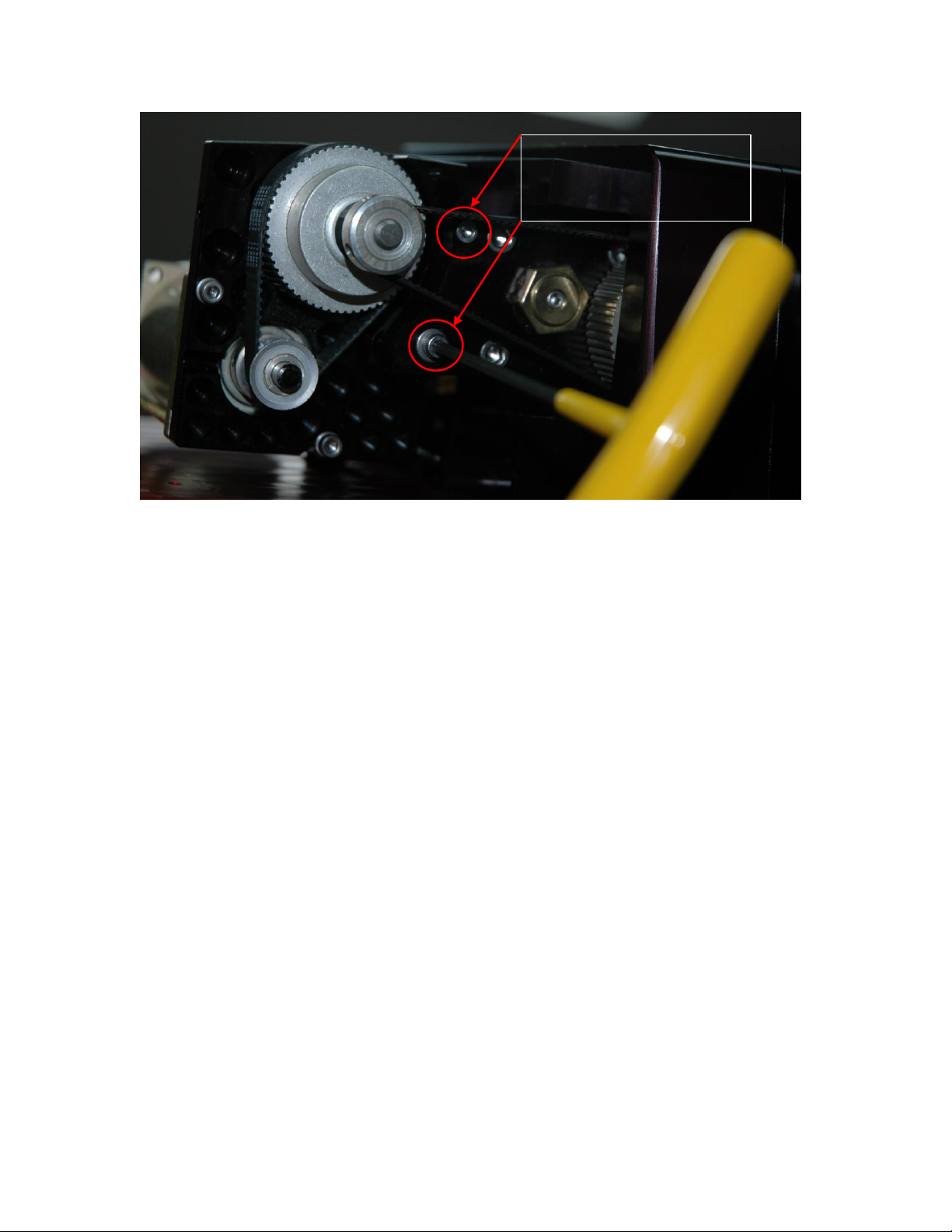
Figure 2: Remove these five socket head cap screws.
Using a 5/32-inch hex wrench, remove the two 5/32-inch socket head cap screws in
Figure 2. Using a 1/8-inch hex wrench, remove the three remaining socket head cap
screws.
Removing the declination cover reveals the declination motor. At this point, we
recommend also removing the back portion of the declination cover to make removing
the declination motor assembly simpler.
5/32 in. hex wrench
Use 1/8 inch hex
wrench

Revision 2.0
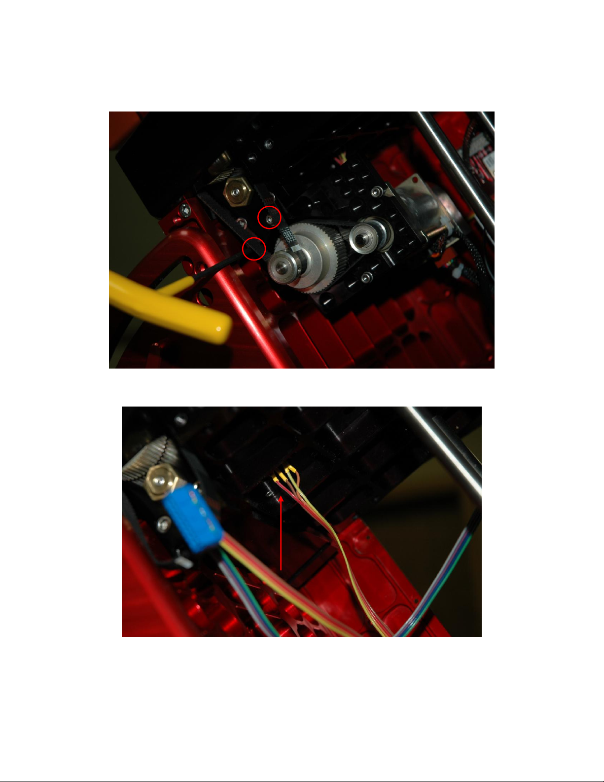
Before proceeding, place a piece of masking tape over the cable access hole in the
declination housing to prevent the socket head cap screws from falling inside.
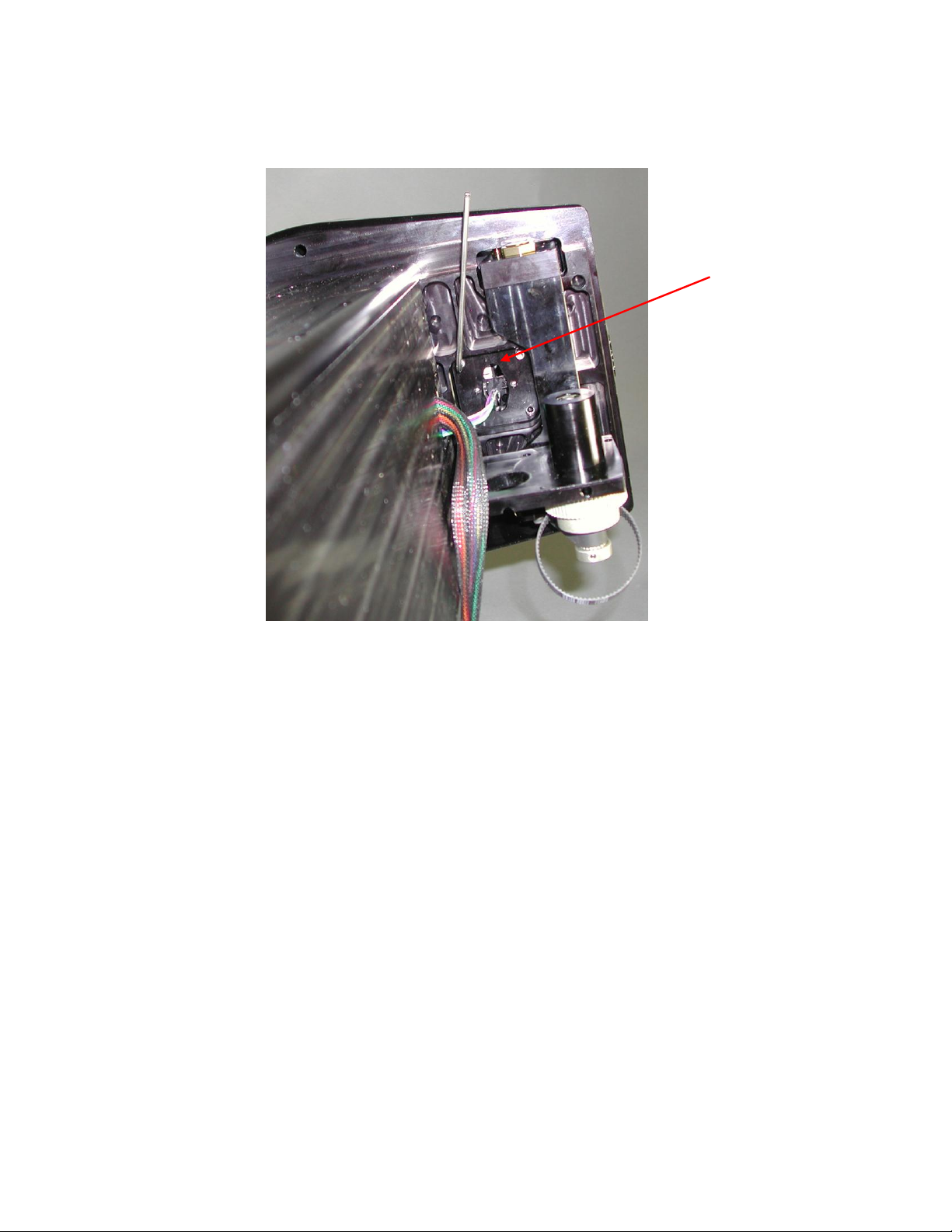
Figure 3: Cover the cable access hole (inside the red circle on the photo) with masking tape to
prevent screws from falling in.
Once the motor wire access hole is covered with tape, use the 3/32 inch T-handle wrench
to remove the seven 3/8 inch socket head cap screws as shown in Figure 4.
Declination axis motor
Declination axis
balance knob
Access hole

Revision 2.0
Figure 4: Removing the back portion of the declination worm block cover.
IMPORTANT: Rotate the declination axis balance knob fully clockwise to separate the
worm from the gear. This also move the declination motor so you can access the four
socket head cap screws that are located near the lower portion of the cover. When
removing the socket head cap screws, while rotating the T-handle hex slowly be sure and
apply downward pressure at the same time so the wrench does not slip.
When the cover has been completely removed, rotate the declination axis in either
direction until a hard stop is encountered. By doing so, the mount’s internal homing
sensor index (that is part of the gear) is completely out of the way of the homing sensor.
The next step is to remove the two 7/64 inch socket head cap screws that mount the speed
reducer to the worm block assembly as shown in Figure 5.
Step 2: Remove the
four socket head cap
screws using a 3/32
inch T-handle hex
wrench.
Step 3: Remove the 3
x 3/32 inch socket
head cap screws using
a T-handle hex
wrench.
Step 1: Rotate the declination axis balance knob fully clockwise to
separate the worm from the gear.
Revision 2.0
Figure 5: Removing the two screws that mount the speed reducer and declination axis motor to the
worm block assembly.
Note the lower socket head cap screw has a washer, the upper screw does not. Please
make sure to replace the screws in the correct holes during reassembly.
The lower screw fits into a slotted hole that allows the gear reducer to be rotated around a
pivot point created by the upper screw. Rotating the assembly counterclockwise (as
viewed in Figure 5) allows belt on the reducer’s pulley to be easily removed. During
reassembly, be sure to rotate the speed reducer fully clockwise (as viewed in Figure 5)
about this pivot point to restore the original tension in the larger belt.
The declination axis motor and speed reducer can be placed on the top of the mount.
Securing the assembly with masking tape is a good idea.
Remove these two 7/64-
inch socket head cap
screws hex wrench.

Revision 2.0
Removing the Declination Sensor
Figure 6: Location of the declination axis homing sensor, looking toward the top of the declination
axis from the bottom.
The homing sensor
housing holds the optical
sensor in place.
This is the homing
sensor itself. Wires
are attached to the
sensor.

Revision 2.0
Figure 7: Hex wrench used to remove socket head cap screws near the declination axis housing.
IMPORTANT: Maintaining the orientation of the homing sensor is critical. If the
assembly is installed incorrectly (by rotating 90 degrees in either direction), when the
declination axis rotates, the mechanical index on the gear will run into the side of the
optical sensor and damage it.
Use a piece of tape, or permanent marker to scribe the correct orientation of the housing
with in the axis. Here is a close up view of the sensor in the sensor housing.
Note the orientation of the
sensor before removing
the mounting screws!

Revision 2.0
Figure 8: Define the orientation of the sensor housing by marking both the assembly and declination
axis.
Once all four homing sensor mounting screws are removed, the next step is to remove the
homing sensor assembly from the mount. The assembly fits very snugly and can be
difficult to remove.
Do not pull in the homing sensor wiring to remove the homing sensor housing!
Insert the end of the needle nose pliers and orient them parallel with the long axis of the
oval hole in the homing sensor housing. Use outward pressure on the needle nose pliers
to capture the homing sensor housing (Figure 9) and extract it.
Mark the orientation of
the sensor housing in the
declination axis.
Revision 2.0
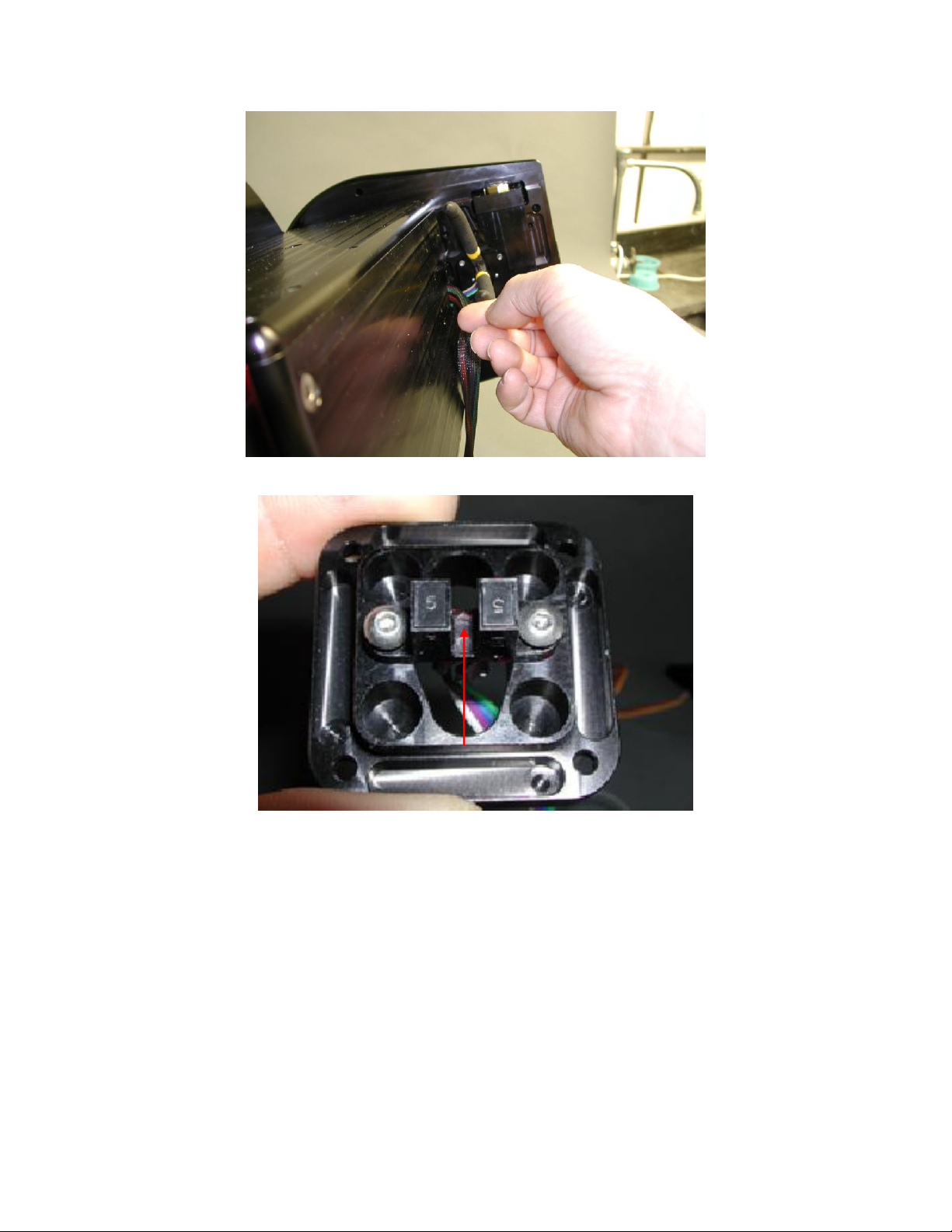
Figure 9: Use outward pressure on the needle nose pliers to carefully remove the sensor housing.
Figure 10: Close-up view of the optical homing sensor in the housing assembly.
Figure 10 show the two 5/64 inch button head cap screws that attach the optical sensor to
the homing sensor housing. If you are replacing the homing sensors, remove both screws
then rotate the optical sensor 90 degrees to remove it from the housing.
Cleaning the Optical Sensor
The red arrow in Figure 10 marks the location of the optical path that must be clear of
grease and other foreign matter for the sensor to function normally.
Before removing the homing sensor housing or the speed reducer, try using a can of
compressed air to clear the optical path. Insert the compressed air’s optional small plastic
nozzle into the oval hole in the homing sensor housing and depress the release valve in
short bursts, then test to see if homing is successful.
Revision 2.0
If this fails, completely remove the homing sensor housing and use an alcohol soaked
cotton swab to clean between the posts marked by the red arrow in Figure 10.
Right Ascension Axis Sensor Replacement
The procedure for accessing and removing the right ascension homing sensor is similar to
removing the declination sensor. Please carefully review “Removing the Declination
Sensor” before proceeding.
The right ascension axis homing sensor sits behind the right ascension gear and must be
accessed by removing one or both of the right ascension housing side panels.
This first step is to rotate the right ascension axis balance knob to separate the worm from
the gear so that the mount swings freely. As always, use appropriate caution.
Next, see “Removing the RA and Dec Side Panels” in the Paramount ME User Guide:
http://www.bisque.com/sc/media/p/28169.aspx for details how to remove the side panel.
If you wish to check the integrity of homing sensor cables or want to try cleaning out the
right ascension axis’ optical sensor with compressed air while troubleshooting homing
failures (see “Cleaning the Optical Sensor”), first remove the panel on the RA housing
box referenced in Figure 35 of the Paramount ME User Guide (this is the panel on the
right side of the mount when looking at the Adaptor Panel).
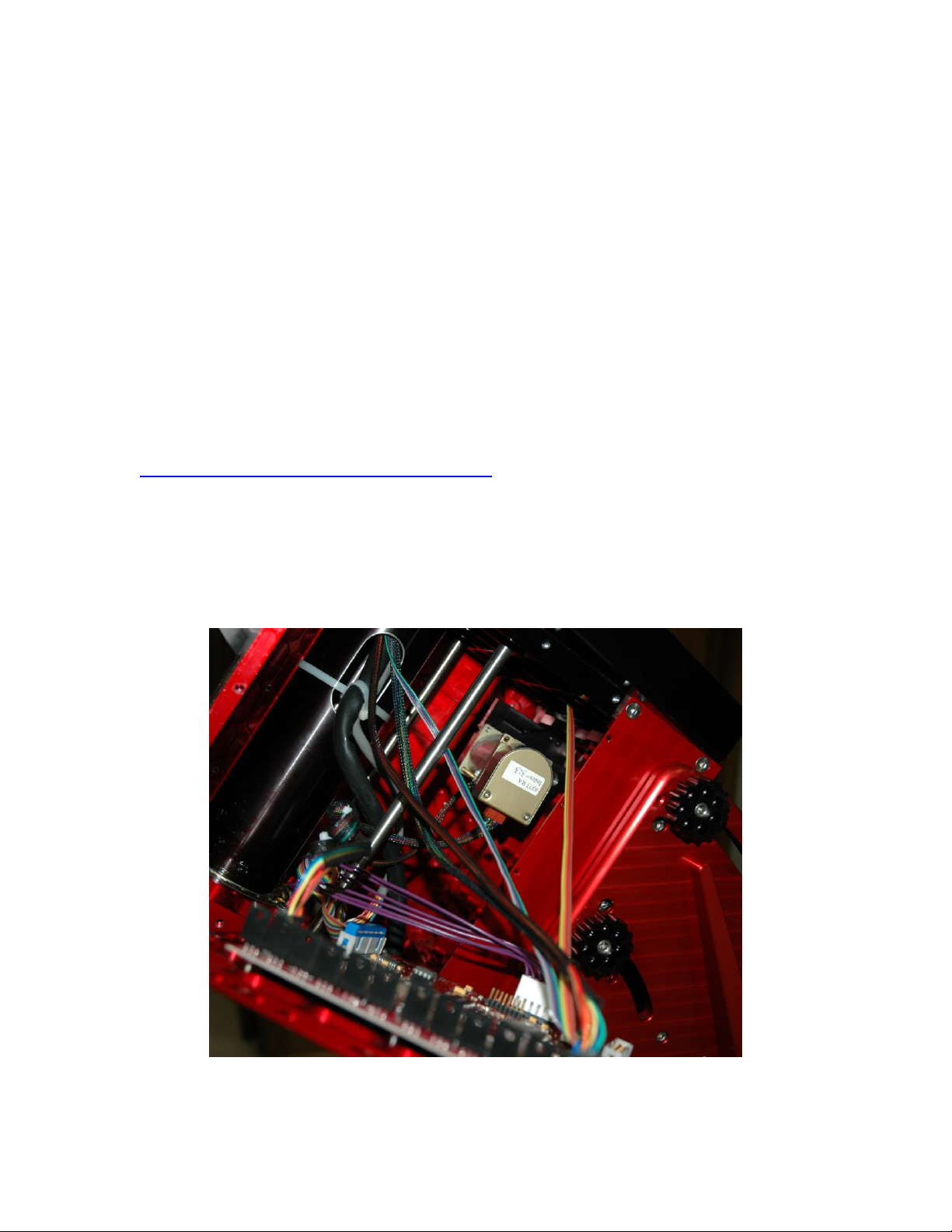
Figure 11: Right ascension housing with the right panel removed. Follow the orange and yellow
cable to locate the homing sensor.

Revision 2.0
If you plan to replace the homing sensor cable, remove both side panels. Having an
incoming light source from both sides of the mount into the dark right ascension box is
very helpful to those of us with older eyes. (If you’re not yet 45, you may not
understand.)
The yellow and orange homing sensor cable shows the way to the homing sensor housing
(Figure 11).
Before performing more disassembly, when this panel is removed, try cleaning the
optical sensor (page 10), then testing whether or not homing works.
To remove the right ascension homing sensor housing, in addition to removing the left
panel on the right ascension housing, the lower side panel must also be removed to access
and easily remove the speed reducer.
Figure 12: Remove the lower panel to access and remove the speed reducer.
Raise the mount’s polar axis until the 1/8 inch socket head cap screws in the bottom of
the lower side panel are aligned with the holes in the wedge. Remove all eight screws
and remove the lower side panel. Note that passing the socket head cap screws through
the holes in the wedge can be tricky. Try adding a small dab of heavy grease to the end
of the hex wrench to give it more cohesion with the screw. If the screw falls off in
between the wedge and the right ascension box, you’ll need to fish it out from the inside
“depressions” in the wedge.
With the lower panel removed, remove the speed reducer and motor assembly, then set it
on the bottom of the right ascension housing. As with the declination motor assembly,
The lower side panel
Holes in the wedge
Revision 2.0
make note of the slotted hole (on the top side here) and the pivot point (created by the
bottom mounting screw).
Figure 13: Removing the two screws that mount the speed reducer and motor assembly.
Figure 14: The right ascension homing sensor housing is now accessible for cleaning, removal and
replacement.
When the two sensor housings have been removed assemble the new sensors. Then the
two units can easily be re-installed.

Revision 2.0
Figure 15: Homing sensors cabling with the homing sensors mounted to the homing sensor housings.
The homing sensors can now be installed by reversing the procedures described above.
See “Through the Mount Cabling” in the Paramount ME User Guide:
http://www.bisque.com/sc/media/p/28169.aspx for details how to run the homing sensor
cable and homing sensor up to the declination axis.
IMPORTANT ASSEMBLY NOTES:
Do not over tighten the two button head cap screws that hold the plastic sensor in
the housing. Over tightening the two screws will deform the optical sensor. Also,
tighten each evenly as opposed to tightening one completely, then the other.
Remember that the sensor orientation is critical.
The longer (teal colored) cable is for the declination axis homing sensor. Before
mounting the homing sensor housing, this cable must be run through. In other
words, you cannot install the declination homing sensor fully assembled as shown
in Figure 10.
Other Bisque Accessories manuals

Popular Accessories manuals by other brands

M/A-Com
M/A-Com P5100 Series installation manual

Wenglor
Wenglor OHK202 operating instructions

FlowLine
FlowLine EchoSwitch LU74 Series quick start

Sensor
Sensor METIS Vision MV05 Assembly and installation instructions

PCB Piezotronics
PCB Piezotronics M102B15 Installation and operating manual

Elko
Elko SmartSensor user guide


