IFM JN2101 User manual

Device manual
Inclination sensor 2 axes
JN2101
from firmware 2.5.0
80269174/00 08/2017
UK

Inclination sensor JN
2
Contents
1 Preliminary note . . . . . . . . . . . . . . . . . . . . . . . . . . . . . . . . . . . . . . . . . . . . . . . . . 4
1.1 Symbols used. . . . . . . . . . . . . . . . . . . . . . . . . . . . . . . . . . . . . . . . . . . . . . . 4
3 Functions and features . . . . . . . . . . . . . . . . . . . . . . . . . . . . . . . . . . . . . . . . . . . . 5
4 Installation . . . . . . . . . . . . . . . . . . . . . . . . . . . . . . . . . . . . . . . . . . . . . . . . . . . . . 5
4.1 Fixing . . . . . . . . . . . . . . . . . . . . . . . . . . . . . . . . . . . . . . . . . . . . . . . . . . . . . 5
4.2 Mounting surface . . . . . . . . . . . . . . . . . . . . . . . . . . . . . . . . . . . . . . . . . . . . 5
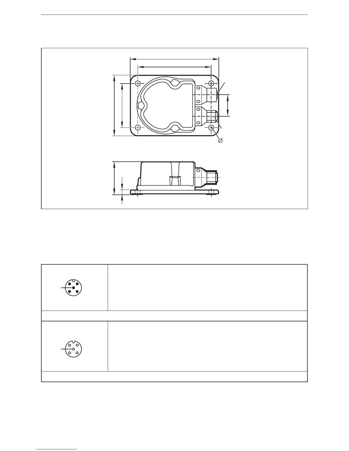
5 Scale drawing . . . . . . . . . . . . . . . . . . . . . . . . . . . . . . . . . . . . . . . . . . . . . . . . . . . 6
6 Electrical connection. . . . . . . . . . . . . . . . . . . . . . . . . . . . . . . . . . . . . . . . . . . . . . 6
6.1 Bus termination . . . . . . . . . . . . . . . . . . . . . . . . . . . . . . . . . . . . . . . . . . . . . 6
7 CANopen interface . . . . . . . . . . . . . . . . . . . . . . . . . . . . . . . . . . . . . . . . . . . . . . . 7
7.1 CANopen functions . . . . . . . . . . . . . . . . . . . . . . . . . . . . . . . . . . . . . . . . . . 7
7.2 Set-up. . . . . . . . . . . . . . . . . . . . . . . . . . . . . . . . . . . . . . . . . . . . . . . . . . . . . 7
7.3 NMT start-up (OD index 1F80h). . . . . . . . . . . . . . . . . . . . . . . . . . . . . . . . . 8
7.3.1 Slave Only (default) (OD index 1F80h = 0) . . . . . . . . . . . . . . . . . . . . 8
7.3.2 NMT start command (OD index 1F80h = 2). . . . . . . . . . . . . . . . . . . . 8
7.3.3 Autostart (OD index 1F80h = 8) . . . . . . . . . . . . . . . . . . . . . . . . . . . . 8
7.4 Communication types of process data object (PDO) . . . . . . . . . . . . . . . . . 8
7.4.1 Cyclical operating mode. . . . . . . . . . . . . . . . . . . . . . . . . . . . . . . . . . . 8
7.4.2 Synchronised transmission after reception of a SYNC telegram . . . . 8
7.5 Object directory (OD) . . . . . . . . . . . . . . . . . . . . . . . . . . . . . . . . . . . . . . . . 10
7.5.1 Communication parameters (to CiA DS-301). . . . . . . . . . . . . . . . . . 12
7.6 Service data object (SDO) mapping. . . . . . . . . . . . . . . . . . . . . . . . . . . . . 14
7.6.1 System settings 0x2000 - 0x203F . . . . . . . . . . . . . . . . . . . . . . . . . . 14
7.6.2 Applicative 0x2040 - 0x207F . . . . . . . . . . . . . . . . . . . . . . . . . . . . . . 14
7.6.3 System settings 0x4000 - 0x403F . . . . . . . . . . . . . . . . . . . . . . . . . . 15
7.6.4 Informative 0x4080 - 0x40BF. . . . . . . . . . . . . . . . . . . . . . . . . . . . . . 15
7.6.5 Profile-specific part (to CiA DSP-410) . . . . . . . . . . . . . . . . . . . . . . . 15
8 Angle definition (SDO index 2044h) . . . . . . . . . . . . . . . . . . . . . . . . . . . . . . . . . 16
8.1 Perpendicular angle (SDO index 2044h = 0) . . . . . . . . . . . . . . . . . . . . . . 16
8.2 Euler angle (SDO index 2044h = 1) . . . . . . . . . . . . . . . . . . . . . . . . . . . . . 16
8.3 Gimbal angle X (SDO index 2044 = 2). . . . . . . . . . . . . . . . . . . . . . . . . . . 17
8.4 Gimbal angle Y (SDO index 2044 = 3) . . . . . . . . . . . . . . . . . . . . . . . . . . . 18
8.5 Explanatory example . . . . . . . . . . . . . . . . . . . . . . . . . . . . . . . . . . . . . . . . 18
9 Other sensor functions . . . . . . . . . . . . . . . . . . . . . . . . . . . . . . . . . . . . . . . . . . . 19
9.1 Node ID (SDO index 2000h) and baud rate (SDO index 2001h) . . . . . . . 19
9.2 Limit frequency digital filter (SDO index 2043h) . . . . . . . . . . . . . . . . . . . . 19
9.3 Set zero point (SDO index 2046h) . . . . . . . . . . . . . . . . . . . . . . . . . . . . . . 19
9.4 Terminating resistor (SDO index 2045h) . . . . . . . . . . . . . . . . . . . . . . . . . 19
9.5 Set teach (SDO index 2042h) . . . . . . . . . . . . . . . . . . . . . . . . . . . . . . . . . 20
9.6 Quadrant correction (SDO index 2040h) . . . . . . . . . . . . . . . . . . . . . . . . . 21
9.7 Heating (SDO index 2041h) . . . . . . . . . . . . . . . . . . . . . . . . . . . . . . . . . . . 21

UK
Inclination sensor JN
3
9.8 MEMS self-test (SDO index 4004h) . . . . . . . . . . . . . . . . . . . . . . . . . . . . . 21
9.9 Temperature of the measuring cell (SDO index 4080h) . . . . . . . . . . . . . . 21
9.10 Inclination values longitudinal and lateral (SDO index 6010h and SDO
index 6020h) . . . . . . . . . . . . . . . . . . . . . . . . . . . . . . . . . . . . . . . . . . . . . . . . . . 22
9.11 Inversion of the angle values . . . . . . . . . . . . . . . . . . . . . . . . . . . . . . . . . 22
9.12 Programming key (SDO index 3000h) . . . . . . . . . . . . . . . . . . . . . . . . . . 22
10 Parameter (connection set) handling . . . . . . . . . . . . . . . . . . . . . . . . . . . . . . . 23
10.1 Save the connection set (OD index 1010h) . . . . . . . . . . . . . . . . . . . . . . 23
10.2 Reset the connection set (OD index 1011h). . . . . . . . . . . . . . . . . . . . . . 23
10.3 Factory reset (SDO index 207Fh) . . . . . . . . . . . . . . . . . . . . . . . . . . . . . 23
11 Emergency messages . . . . . . . . . . . . . . . . . . . . . . . . . . . . . . . . . . . . . . . . . . 24
11.1 Failure monitoring. . . . . . . . . . . . . . . . . . . . . . . . . . . . . . . . . . . . . . . . . . 24
11.1.1 Node guarding / life guarding . . . . . . . . . . . . . . . . . . . . . . . . . . . . . 24
11.1.2 Heartbeat . . . . . . . . . . . . . . . . . . . . . . . . . . . . . . . . . . . . . . . . . . . . 24
11.2 COB IDs . . . . . . . . . . . . . . . . . . . . . . . . . . . . . . . . . . . . . . . . . . . . . . . . . 25
11.3 Status LED . . . . . . . . . . . . . . . . . . . . . . . . . . . . . . . . . . . . . . . . . . . . . . . 25
12 Maintenance, repair and disposal. . . . . . . . . . . . . . . . . . . . . . . . . . . . . . . . . . 26
13 Approvals/standards . . . . . . . . . . . . . . . . . . . . . . . . . . . . . . . . . . . . . . . . . . . . 26
14 Factory setting . . . . . . . . . . . . . . . . . . . . . . . . . . . . . . . . . . . . . . . . . . . . . . . . . .
This document is the original instructions.

Inclination sensor JN
4
1 Preliminary note
Technical data, approvals, accessories and further information at www.ifm.com.
This document applies to the device of type „inclination sensor“ (art. no.: JN2100).
It is part of the device.
This document is intended for specialists. These specialists are people who are
qualified by their appropriate training and their experience to see risks and to
avoid possible hazards that may be caused during operation or maintenance of
the device. The document contains information about the correct handling of the
device.
Read this document before use to familiarise yourself with operating conditions,
installation and operation. Keep this document during the entire duration of use of
the device.
Adhere to the safety instructions.
1.1 Symbols used
►Instructions
> Reaction, result
[…] Designation of keys, buttons or indications
→Cross-reference
Important note
Non-compliance may result in malfunction or interference.
Information
Supplementary note
2 Safety instructions
●Read this document before setting up the product and keep it during the entire
service life.
●The product must be suitable for the corresponding applications and environ-
mental conditions without any restrictions.
●Only use the product for its intended purpose (Functions and features).
●If the operating instructions or the technical data are not adhered to, personal
injury and/or damage to property may occur.
●The manufacturer assumes no liability or warranty for any consequences
caused by tampering with the product or incorrect use by the operator.
●Installation, electrical connection, set-up, operation and maintenance of the unit
must be carried out by qualified personnel authorised by the machine operator.
●Protect units and cables against damage.

UK
Inclination sensor JN
5
3 Functions and features
The 2-axis inclination sensor with CANopen interface enables angle levelling and
position detection of mobile machines.
Typical applications are, for example, the position detection of access platforms,
levelling of mobile cranes or set-up of mobile machines.
Properties:
●2-axis inclination sensors with a measuring range of ±45°
●High accuracy and resolution
●CANopen interface to CiA DS-301 and device profile CiA DSP-410
●The module supports „LSS-Slave“, "node guarding" and "heartbeat"; "guard
time", "life time factor" as well as "heartbeat time" can be configured.
●High sampling rate and band width
●Configurable limit frequency (digital filter) for vibration suppression
●CANopen functions
– Transmit PDOs (RTR, cyclical, synchronised)
– SYNC consumer (synchronised transmission of the transmit PDOs after
reception of a SYNC telegram)
– EMCY producer (exceeding of limit value, monitoring of the inside device
temperature)
– Failure monitoring by means of heartbeat or node guarding / life guarding
●Programming key
●Inversion of the angle values / reversal of direction of rotation
●Automatic data backup (autosave) and autostart function
4 Installation
4.1 Fixing
►Fasten the device using 4 M5 screws on a flat surface.
Screw material: steel or stainless steel.
4.2 Mounting surface
The housing must not be exposed to any torsional forces or mechanical
stress.
►Use compensating elements if there is no flat mounting surface available.

Inclination sensor JN
6
5 Scale drawing
33,2
4,5
90
75
22
45
62
5,3
M12x1
M12x1
6 Electrical connection
The inclination sensors are fitted with two round 5-pole M12 connectors (A-coded).
The pin connection corresponds to the CANopen specification CiA DR-303-1.
4
21
3
5
1: CAN_SHLD CAN shield
2: CAN_V+ Supply voltage 24 V DC (+UB)
3: CAN_GND Ground
4: CAN_H High bus cable
5: CAN_L Low bus cable
M12 connector CAN-In
3
12
4
5
1: CAN_SHLD CAN shield
2: CAN_V+ Supply voltage 24 V DC (+UB)
3: CAN_GND Ground
4: CAN_H High bus cable
5: CAN_L Low bus cable
M12 socket CAN-Out
6.1 Bus termination
The inclination sensors have an internal terminating resistor that can be activated
via the CANopen interface (SDO-Index 2045h; activated by default).

UK
Inclination sensor JN
7
7 CANopen interface
The inclination sensors have a standardised CANopen interface to CiA DS-301
and a device profile to CiA DSP-410. All measured values and parameters can be
accessed via the object directory (OD). The individual configuration can be saved
in the internal permanent memory (flash).
7.1 CANopen functions
The following CANopen functions are available:
●Several transmit data objects (TPDO) in four possible operating modes:
– individual check via a remote transmit-request telegram (RTR)
– cyclical transmission per interval time
– synchronised transmission after reception of a SYNC telegram
– a service data object (default SDO)
●Error messages per emergency object (EMCY) with support of the:
– general error register
– manufacturer-specific register
– error list (pre-defined error field)
●Monitoring mechanisms heartbeat and node guarding/life guarding
●Status and error indication via LED
●In addition to the basic CANopen functions there are other manufacturer and
profile-specific features:
– setting of the node ID and the baud rate via OD
– configurable limit frequency (digital filter)
7.2 Set-up
The CANopen standard CiA DS-301 defines three possible states for sensor
nodes.
Pre-operational
The pre-operational state is used to set the sensor parameters or as standby
mode. In the pre-operational state no process data (PDO messages) can be
transmitted.
Operational
The operational state is used to exchange the process data while in operation. In
the operational state all communication services are carried out.
Stopped
The stopped state is used for network management; only NMT messages are
possible.

Inclination sensor JN
8
The master or network manager can request the sensor via NMT messages to
change the state accordingly. This allows almost complete separation of redundant
or faulty sensors from the bus.
7.3 NMT start-up (OD index 1F80h)
The sensor has a selectable start performance. The following three options can be
selected under the index 1F80h:
7.3.1 Slave Only (default) (OD index 1F80h = 0)
The sensor starts in the pre-operational state (0x00h).
7.3.2 NMT start command (OD index 1F80h = 2)
This command is used for CAN bus networks without NMT master. If the sub-
index 0x02h is selected, the sensor starts after a new start as NMT master in the
operational state and sets the other network participants from the pre-operational
into the operational state.
7.3.3 Autostart (OD index 1F80h = 8)
If the value 0x08h of this index is written, the sensor automatically boots in the
operational state when rebooted.
7.4 Communication types of process data object (PDO)
The request for process data objects is made by sending a remote transmit
request telegram (RTR).
The different transmit PDOs (TPDOx) can be polled in all operating modes of the
inclination sensor individually and at any time.
7.4.1 Cyclical operating mode
The cyclical transmission of a TPDO is activated when the interval time (e.g.
OD index 1800h/05h for TPDO0) contains a value greater than 0. The type of
transmission (e.g. OV index 1800h/02h for TPDO0) has to be set to "asynchronous
– manufacturer-specific“ (value = FEh). In the "operational" state the inclination
sensor then cyclically transmits the TPDO0 with the set interval time.
7.4.2 Synchronised transmission after reception of a SYNC telegram
For the synchronised transmission CANopen provides the SYNC object at which
the TPDOs are transmitted after every "nth" reception of a SYNC telegram.
Each inclination sensor has several transmit process data objects (TPDO0). The
TPDO1 contains the current inclination values (longitudinal and lateral) as 16-bit
values.
Byte 0 Byte 1 Byte 2 Byte 3

UK
Inclination sensor JN
9
Inclination value longitudinal
(X axis)
OD index: 6010h
Inclination value lateral
(y axis)
OD index: 6020h
The second transmit process data object TPDO1 contains the inclination values as
32-bit values.
Byte 0 to byte 3 Byte 4 to byte 7
Inclination value longitudinal
(X axis)
OD index: 6110h
Inclination value lateral
(y axis)
OD index: 6120h
The resolution of the inclination information (SDO index 6000h) can be configured
accordingly. For the settings see the device profile for inclination sensors (CiA
DSP-410: SDO index 0x6000 – 0x9FFF).
A list with the individual values can be found in chapter "7.6.5 Profile-specific part".

Inclination sensor JN
10
7.5 Object directory (OD)
Index Sub-
index
Name (parameter) Type Default value
(factory set)
Autosave
/ Reset
1000h
0 Device type
(device profile 410, 2 axes)
const u32 4019Ah
1001h
0 Error register ro u8 0
1003h
Pre-defined error field
0 Number of error entries rw u32 0
1...50 Error code
(oldest error at highest index)
ro u32 0
1005h
0 COB ID sync message rw u32 80h
1008h
0 Product designation const VSTR JN2101
1009h
0 Hardware version const VSTR X.Y.Z
100Ah
0 Software version ("XYY") const VSTR X.Y.Z
100C h
0 Guard time
(multiple of 1 ms)
rw u16 0 Yes
100D h
0 Life time factor rw u8 0 Yes
1010h
Save parameters
0 Highest supported sub-index r0 u32 1
1 Save all parameters
(all parameters are saved
automatically in case of a change
and will be active after rebooting)
rw u32 2 (Autosave) Yes
1011h
Restore factory parameters u32
0 Highest supported sub-index r0 u32 1
1 Restore all factory parameters
(signature: "load" - 64616F6 Ch)
rw u32 0
1014h
0 COB ID EMCY (emergency
message)
ro u32 80h + node ID
1015h
0 Disable time between EMCY
messages
(multiple of 100 µs)
rw u16 0 Yes
1017h
0 Heartbeat interval time
(multiple of 1 ms, 0 deactivated)
rw u16 0 Yes
1018h
Identity object
0 Highest supported sub-index ro u8 4
1 Vendor ID ro u32 6D666900
2 Product code ro u32 01
3 Revision number ro u32 AA
4 Serial number ro u32 Typical

UK
Inclination sensor JN
11
Index Sub-
index
Name (parameter) Type Default value
(factory set)
Autosave
/ Reset
1029h Error behaviour object
0 Number of error classes ro u8 1 No
1 Error behaviour rw u8 0 0x0
1200h Server SDO parameter
0 Highest supported sub-index ro u8 2
1 COB ID client to server ro u32 600h + node ID
2 COB ID server to client ro u32 580h + node ID
1800h
Transmit PDO0 communication parameter
0 Highest supported sub-index ro u8 5
1 COB ID ro u32 180h + node ID
2 Type of transmission
(synchronous + asynchronous,
manufacturer-specific)
rw u8 1 Yes
3 Disable time between
two TPDO messages
(multiple of 100 µm)
rw u16 0 Yes
5Interval time for cycl. transmission
(multiple of 1 ms,
0 deactivated)
rw u16 10 Yes
1801h
Transmit PDO1 communication parameters
0 Highest supported sub-index ro u8 5
1 COB ID ro u32 280h + node ID
2 Type of transmission
(synchronous/asynchronous)
rw u8 1 Yes
3 Disable time between
two TPDO messages
(multiple of 100 µs)
rw u16 0
5Interval time for cycl. transmission
(multiple of 1 ms,
0 deactivated)
rw u16 10 Yes
1A00h
Transmit PDO0 mapping parameter (fixed mapping)
0 Highest supported sub-index ro u8 2 Yes
1 Inclination value longitudinal
(X axis)
ro u32 60100010h
2 Inclination value lateral
(Y axis)
ro u32 60200010h

Inclination sensor JN
12
Index Sub-
index
Name (parameter) Type Default value
(factory set)
Autosave
/ Reset
1A01h
Transmit PDO1 mapping parameter (fixed mapping)
0 Highest supported sub-index ro u8 2 Yes
1 Inclination value longitudinal
(X axis)
ro u32 61100020h
2 Inclination value lateral
(Y axis)
ro u32 61200020h
1F80h
NMT start-up
0 Slave only rw u8 0 Yes
2 Start-up capable device
NMT start command
rw 2
8 Start-up capable device
autostart feature only
rw 8
Values for error behaviour (see 1029h)
0 = pre-operational (only if current state is operational)
1 = no change of state
2 = stopped
3 .. 127 = reserved
7.5.1 Communication parameters (to CiA DS-301)
Error register (OD index 1001h)
The error register indicates the general error status of the device. Every bit stands
for an error group. If a bit is set (= 1), at least one error of this group is active at
the moment. The contents of this register are transmitted in every emergency
message (EMCY).
Error groups
Bit 5...7 bit 4 = 0 bit 3 = 0 bit 2 = 0 bit 1 = 0 Bit 0
Not used Communication error
(overrun)
Temperature Voltage Not used At least one
error active
Pre-defined error field (OD index 1003h)
Each inclination sensor has an error list with the 50 most recent errors. The pre-
defined error field (OD index 1003h) contains the number of error entries (OD
index 1003h/00h).
The other sub-indices contain the saved error states in chronological order with
the error occurred last being always found under the lowest sub-index (OD index
1003h/01h).

UK
Inclination sensor JN
13
The oldest error is in the highest available sub-index and is the first to be removed
from the list in the case of more than 50 errors.
If an error occurs, a new error entry is added to the error field (OD index 1003h)
and also communicated via an EMCY message.
Structure of an error entry
Byte 0 Byte 1 Byte 2 Byte 3 Byte 4 Byte 5 Byte 6 Byte 7
Emergency error
Code
Error register
(object 1001h)
Manufacturer-specific error field
Emergency error code Meaning
00xxh Error reset or no error
10xxh Generic error
31xxh Mains voltage
32xxh Voltage inside the device
41xxh Ambient temperature
42xxh Device temperature
5010h Sensor error; X angle value outside of the
measuring range
5020h Sensor error; Y angle value outside of the
measuring range
80xxh Monitoring
81xxh Communication
8110h CAN overrun (objects lost)
8120h CAN in error passive mode
8130h Life guard error or heartbeat error
8140h Recovered from bus off
8150h Transmit COB ID
82xxh Protocol error
8210h PDO not processed due to length error
8220h PDO length exceeded
90xxh External error
F0xxh Additional functions

Inclination sensor JN
14
7.6 Service data object (SDO) mapping
7.6.1 System settings 0x2000 - 0x203F
SDO
index
Sub-
index
Type Value Unit r/w Reset
0x2000 0x0 u8 Node ID rw Yes
0x2001 0x0 u16 Baud rate Kbit rw Yes
0x2002 0x0 u8 Flag to reset the sensor
Flag = 1 sensor reset
0 rw
7.6.2 Applicative 0x2040 - 0x207F
SDO
index
Sub-
index
Type Value Unit r/w Reset
0x2040 0x0 u8 Flag for quadrant correction
0: off
1: on ± 180
2: on ± 0
360°
rw
0x2041 0x0 u8 Flag for heating
Flag = 0 heating off
Flag = 1 heating on
rw
0x2042 0x0 u8 Index teach values of the X/Y/Z axes
0: no change
1: set teach, relative measurement
2: reset teach, absolute measurement
rw
0x2043 0x0 u8 FIR filter for angle measurement
0: FIR deactivated
1: FIR 10 Hz
2: FIR 5 Hz
3: FIR 1 Hz
4: FIR 0.5 Hz
rw
0x2044 0x00 u8 Angle calculation
0: perpendicular
1: Euler
2: gimbal 1X
3: gimbal 1Y
rw
0x2045 0x00 u8 CAN 120 Ω terminating resistor
0: resistor deactivated
1: resistor activated
rw
0x2046 0x0 u8 Set zero point of the X / Y axes
0: unchanged
1: set zero (corresponds to the
relative measurement)
2. reset set zero (corresponds to the
absolute measurement)
rw
0x207F 0x0 u8 Factory reset
1: make factory reset

UK
Inclination sensor JN
15
SDO
index
Sub-
index
Type Value Unit r/w Reset
0x3000 0x0 Programming key rw
0x4001 0x0 ASCII Configuration 1 (Manufacturer only) wo
7.6.3 System settings 0x4000 - 0x403F
SDO
index
Sub-
index
Type Value Unit r/w Reset
0x4004 0x0 u8 MEMS self-test
Number sub-indices
r
0x4004 0x01 u8 Flag to activate the self-test
Flag = 1
→
start self-test
rw
0x4004 0x02 u8 Self-test register
X axis pass
→
bit 2 = 1
X axis fail
→
bit 2 = 0
Y axis pass
→
bit 1 = 1
Y axis fail
→
bit 1 = 0
r
7.6.4 Informative 0x4080 - 0x40BF
SDO
index
Sub-
index
Type Value Unit r/w Reset
0x4080 0x0 Integer
32
MEMS temperature 1/10 °C r
0x4081 0x0 u16 Heating power mW r
7.6.5 Profile-specific part (to CiA DSP-410)
SDO
index
Sub-
index
Type Value Unit r/w Auto-
save /
Reset
0x6000 0x0 u16 Resolution
1d = 0.001°
10d = 0.01°
100d = 0.1°
1000d = 1.0°
rw Yes
0x6010 0x0 Integer
16
Longitudinal X axis Angle [°] rw Yes
0x6011 0x0 u8 Slope long16 operating parameter rw Yes
0x6020 0x0 Integer
16
Lateral Y axis Angle [°] rw Yes
0x6021 0x0 u8 Slope lateral16 operating parameter rw Yes
0x6110 0x0 Integer
32
Longitudinal X axis Angle [°] rw Yes
0x6111 0x0 u8 Slope long32 operating parameter r

Inclination sensor JN
16
SDO
index
Sub-
index
Type Value Unit r/w Auto-
save /
Reset
0x6120 0x0 Integer
32
Lateral Y axis Angle [°] rw Yes
0x6121 0x0 u8 Slope lateral32 lateral operating
parameter
rw Yes
8 Angle definition (SDO index 2044h)
To be able to adapt the inclination sensor to the different applications as easily
as possible, the measured inclination information is converted into different angle
indications. The requested angle indication is set by selecting the respective
option.
With this angle definition a sensor coordinate system is used which is defined as
follows:
– The mounting plane corresponds to the XY plane.
– The Z axis is perpendicular to the mounting plane (according to the right-
hand rule).
– The X axis is represented by an edge of the mounting plate which shows in
direction of the printed X arrow.
– The Y axis is then perpendicular to the plane spanned by the Z and X axes.
8.1 Perpendicular angle (SDO index 2044h = 0)
Using the indication of the two perpendicular angles the inclination of the sensor
coordinate system towards the direction of gravitation is described.
The first provided value corresponds to a rotation about the Y axis of the sensor
and is called "longitudinal inclination value" (SDO index 6010h or 6110h).
The value corresponds to the angle [°] between the gravitation vector and the YZ
plane of the sensor.
The second provided value corresponds to a rotation about the X axis of the
sensor and is called "lateral inclination value" (SDO index 6020h or 6120h). The
value corresponds to the angle [°] between the gravitation vector and the XZ plane
of the sensor.
In the case of an inclination in a plane (rotation of an axis with the second axis remaining
perpendicular) the perpendicular angle and gimbal angle are always identical.
8.2 Euler angle (SDO index 2044h = 1)
In this setting the two provided angle values are to be interpreted as Euler angle.

UK
Inclination sensor JN
17
The current sensor orientation is determined by two successive rotations from the
horizontal position.
The "inclination value longitudinal" indicates the angle [°] at which the Z axis of
the sensor is inclined. The "inclination value lateral" corresponds to the angle [°] at
which the sensor was then rotated about the (inclined) Z axis.
Interpretation
The first angle value corresponds to the angle between the gravitation vector and
the sensor's Z axis (slope inclination, gradient angle) whereas the second angle
value indicates the direction in which the slope inclination matches the coordinate
system.
Value range for this option
– Inclination value longitudinal (gradient angle): -45°…+45°
– Inclination value lateral (angle of direction): 0°…360°
Critical point
With a gradient angle of 0° the sensor is in a horizontal position. In this position the
second angle (angle of direction) is useless. In practice, it is to be expected that
the value of the second angle will vary very strongly even if the sensor is virtually
motionless.
8.3 Gimbal angle X (SDO index 2044 = 2)
As with the Euler angle the current orientation of the sensor is described by two
successive rotations from the horizontal position.
But the current orientation now arises from a rotation about the Y axis with the
angle value [°] indicated by the "inclination value longitudinal" as well as from
a rotation which then follows about the (now rotated) X axis with the angle [°]
"inclination value lateral".
Interpretation
If you imagine the sensor as a plane whose body shows in X direction and
whose wings in Y direction, the "inclination value longitudinal" corresponds to the
longitudinal inclination of the plane (pitch angle) and the "inclination value lateral"
to the bank angle (roll angle) of the plane.
Value range
– Inclination value longitudinal: -45°…45°
– Inclination value lateral: -45°…45°
Critical point
With a longitudinal inclination of ± 90° ("plane" flies vertically downwards or
upwards) the roll angle makes a rotation about the gravitational axis which cannot

Inclination sensor JN
18
be detected by the inclination sensor. In this condition the "inclination value lateral"
is insignificant. In practice, the "inclination value lateral" will vary very strongly
when it is close to this condition even if there is only little movement.
8.4 Gimbal angle Y (SDO index 2044 = 3)
This setting corresponds to the setting described in 8.3 with the difference that the
order of the two rotations is now inverted.
In this option the measured object is first rotated about its X axis with the angle
[°] "inclination value lateral". The measured object is then rotated about the Y axis
(which is now inclined) with the angle value [°] indicated by the "inclination value
longitudinal" of the sensor.
As a result of this the measured values of the gimbal angle X and the gimbal angle
Y are identical as long as the measured object is only rotated about one of the
sensor's axes. The measured values of the two options do not differ until a general
rotation is made about the two sensitivity axes.
8.5 Explanatory example
The different angle definitions will be illustrated using a simple example. An
excavator moves up and down an embankment (illustration). The embankment is
angled at 30°. The inclination sensor is installed so that the y axis of the sensor
shows in driving direction of the excavator.
1
2
3
4
5
6
Excavator
position
Perpendicular angle Euler Gimbal X Gimbal Y
Longitudinal Lateral Longitudinal Lateral Longitudinal Lateral Longitudinal Lateral
10° 0° 0° Undefined 0° 0° 0° 0°
20° -30° 30° 0° 0° -30° 0° -30°
320° -20° 30° 45° 20° -22° 22° -20°
430° 0° 30° 90° 30° 0° 30° 0°
530° 0° 30° 90° 30° 0° 30° 0°
60° 30° 30° 180° 0° 30° 0° 30°

UK
Inclination sensor JN
19
9 Other sensor functions
9.1 Node ID (SDO index 2000h) and baud rate (SDO index 2001h)
In the case of a change node ID and baud rate do not become effective until after
a reset (reset application, reset communication or hardware reset).
After a reset, all COB IDs will be recalculated and set according to the pre-defined
connection set → Chapter 11.2 COB IDs.
The inclination sensor from ifm is delivered with the node ID 10 and a baud rate of 125 Kbits/s.
The following baud rates [kBit/s] are supported: 10, 20, 50, 125, 250, 500, 800 and 1000.
9.2 Limit frequency digital filter (SDO index 2043h)
With the sensor it is possible to make continuously arising angle values insensitive
to external interfering vibrations.
Using a configurable low-pass filter (digital FIR filter), interfering vibrations can
be suppressed. The limit frequency of the filter is set via the FIR filter step (SDO-
Index 2043h. In the sensor, several pre-set filter steps (0.5…10Hz) are available.
9.3 Set zero point (SDO index 2046h)
To set the zero point the sensor is rotated to the requested position and the current
position is set as "0". The value of the parameter "set zero point and y axis" (SDO
index 2046h) is to be set to 1.
The sensor then calculates the offset to the zero point shift and saves it in the
permanent memory. From then on the offset is subtracted from the angle.
9.4 Terminating resistor (SDO index 2045h)
In bus topology a CANopen system is terminated with terminating resistors (120 Ω)
at the beginning and end. If the sensor is at the beginning or end, the terminating
resistor (SDO index 2045h) integrated in the sensor can be activated by writing the
value 1.

Inclination sensor JN
20
9.5 Set teach (SDO index 2042h)
Should it not be possible to integrate the inclination sensor into the measured
object so that the coordinate system of the sensor and object match, the teach
function enables the creation of a new reference system.
The new reference system Xb,Yb, Zbis defined so that its Zbdirection corresponds
to the direction of gravitation at the teach moment. The Xbdirection of the
reference system results from the projection of the Xsaxis of the sensor to the XbYb
plane of the reference system.
The Yb axis then corresponds to the direction which is perpendicular to both the Zb
and the Xbaxis.
The result of this is that at the teach moment the Xs axis must not be parallel to the direction of
gravitation. As long as the value for the SDO index 2042h is 1, all angle indications are converted into
the new reference system.
The teach operation can, for example, be as follows:
The measured object with the non-aligned inclination sensor is brought into a
known horizontal position. In this position the teach function is carried out, thus
defining the new reference system. All provided angle values then refer to this new
reference system.
Even with an inclination sensor which is installed at an angle note that the X axis (Xs axis) of the
sensor is parallel to the XBZB plane of the requested reference system.
Explanatory example
Inclination sensor installed at an angle in the
coordinate system of the workpiece. The coordinate
system of the sensor is transferred to the coordinate
system of the workpiece by teaching the sensor
when the workpiece is horizontally aligned.
The raw data of the sensor is indicated in the
coordinate system of the sensor.
In teach mode the data is converted into the
coordinate system of the workpiece.
The example shows a rotation of 30° about the y axis of the coordinate system of
the workpiece.
Table of contents
Other IFM Accessories manuals

IFM
IFM OID20 Series User manual

IFM
IFM LK 022 Series User manual

IFM
IFM PK752 Series User manual

IFM
IFM Ecomat 100 EC2082 Guide

IFM
IFM OID20 Series User manual

IFM
IFM OG Use and care manual

IFM
IFM UGT58 Series User manual

IFM
IFM LMT 0 Series User manual

IFM
IFM O2D54 Series User manual

IFM
IFM efector 200 O4P2 Series User manual
Popular Accessories manuals by other brands

Baumer
Baumer UNCK 09U6914/KS35A quick start guide

Hunter
Hunter DSP700 Series manual

Focusrite
Focusrite iTrack Pocket user guide

Crafstman
Crafstman 917.250220 operating instructions

E+E Elektronik
E+E Elektronik EE300Ex user manual

Van Air Systems
Van Air Systems AC-140 Installation, operation & maintenance instructions