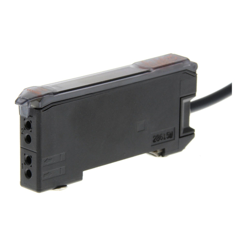
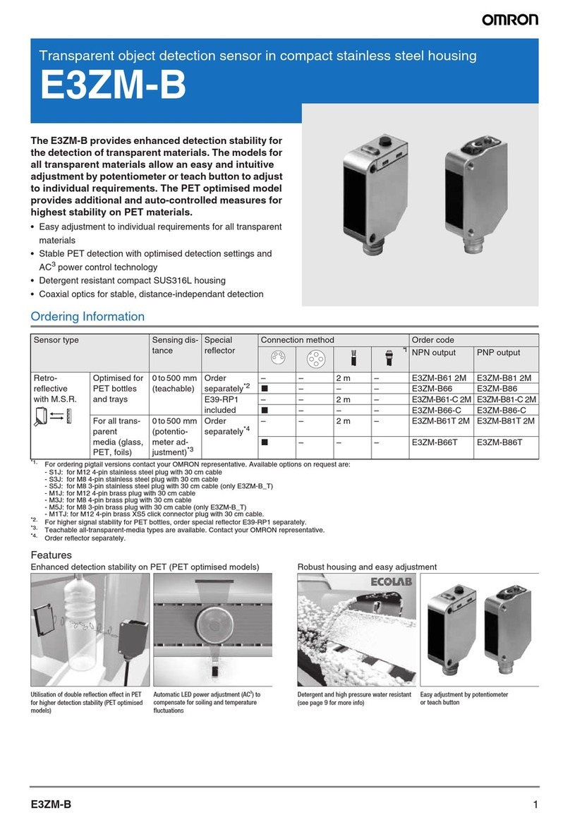
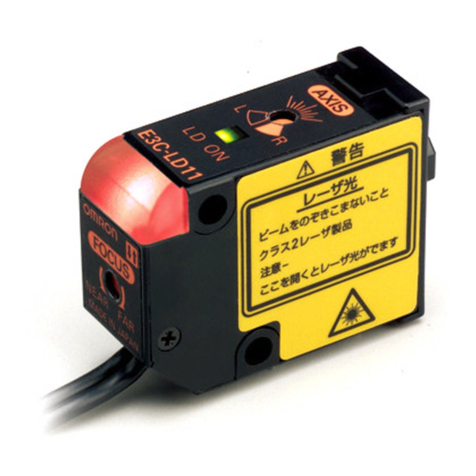
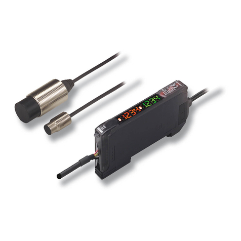
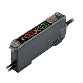
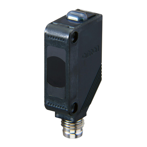
Omron E3X-DA11TW User manual

©OMRONCorporation2000 AllRightsReserved.
取扱説明書
オムロン製 品をお 買いあげいただきありがとうございます 。
この製品を安 全に正しくご使用いただくため、お使いになる前にこの取扱説明書をお読みになり、十
分にご理解ください 。
お読みになった後も、いつもお手元に置いてご利用ください 。
形
E3X-DA□□TW
以下に示す項目は安全を確保するうえで必 要なことですので 必 ず守ってください 。
1)引火性・爆発性ガスの環境では使用しないでください 。
2)製品の分解、修理・改造をしないでください 。
3)定格範囲を超える電圧、電流を印加しないでください 。
4)電源の極性など、誤配線をしないでください 。
5)負荷の接続を正しく行ってください
6)負荷の両端を短絡させないでください 。
安全上の要点
デジタルファイバ光電センサ
使用上の注意
1)電力線、動 力線と光 電スイッチの配線が同一配管あるいはダクトで行われると誘 導を受け 、誤
動作あるいは破損の原因となる場合もありますので、別配線またはシールドコードの使用を原
則としてください 。
2)
コードの延長は0.3mm2以上の線を用い、100m以下としてください。
韓国S-mark認定機種を認定品として使 用される場合は10m未満としてください。
3)コード部に加わる力は下記の値以下としてください 。
引っ張り80N以下、トルク0.1N・m以下、押圧20N以下、屈曲3kg以 下
4)電源投入時の動作
電源を入れてから、E3X-DAが検出可能となる時間は200ms以下です。負荷とE3X-DAが
別電源に接続されている場合は、必ずE3X-DAの電源を先に投入してください 。
5)EEPROM書き込みエラーについて
感度設定(ティーチング)時の電源遮断や静電気などのノイズにより書き込みエラー(動作表
示灯(橙):点滅)が発生した場合、本体の設定キーによる感度設定(ティーチング)を再度行
ってください 。
6)保護カバーは必ず装着した状態でご使用ください 。
■定格/性能 アンプユニット
(*)
(**)
(***)
適用コネクタ E3X-CN21(親コネクタ4芯)、E3X-CN22(子コネクタ2芯)どちらの
コネクタも使 用できます。
エコモード時、デジタル表示消灯時は別売のモバイルコンソールE3X-MC11からのみ
設定可能です。
モバイルコンソールE3X-MC11からは、最大16チャンネル(E3X-DA□□TW8台)が
設定可能です。(ただし、動作モード、エリア 検 出 は 設 定 できませ ん 。)
■各部の名称・機能
チャンネル切替SW
CH1/CH2の切替
モード切替SW
SET.ADJ.RUNの切替
レベル表示灯
動作表示灯(橙色)
出力ON時に点灯
設定キー
ティーチング、しきい 値 の 調 整
機能変更、表示切替など
ADJ
ADJ
SET
TEACH MODE
RUN
CH1
1
2
CH2
接続方式
制御出力
通常時 :消費電力 960mW(電源電圧24V時消費電流40mA)
エコモード時 :消費電力 720mW(電源電圧24V時消費電流30mA)
デジタル表示消灯時:消費電力 600mW(電源電圧24V時消費電流25mA)
オープンコレクタ(DC26.4V以下)
負荷電流:50mA以下、残留電圧:1V以下、オフ状態電流0.5mA以下
NPN
PNP
DA11TW
DA41TW
プリワイヤタイプ コネクタタイプ(*)
形式
(E3X-)
DA6TW
DA8TW
投光素子
電源電圧
消費電力(**)
赤色LED
DC12〜24V±10%リップル10%以下
0〜200ms(1〜20ms:1ms単位、20〜200ms:5ms単位)タイマ 機 能
■操作手順
1.操作の基本…各設定モード(SET/ADJ/RUN)と設定できること
2.感度調整したい時
(しきい 値 )
(パーセント)
(アナログ)
(入光量)
(パーセント)
(アナログ)
モード
SETモード
TEACH
モード
モード
モード
1.ティーチング(自動感度調整)
最大感度設定
1点ティーチング(ワークなしティーチング)
点ティーチング(ワークあり/なしティーチング)
ピンポイントティーチング(位置決めティーチング)
ADJモード
RUNモード
2.各種機能設定
詳細は6項「各種機能設定について」
を参照下さい。
チャンネル切替SWで指定した
チャンネル の 調 整 が できます 。
詳細は2.2項「感度を微調整したい時」
を参照下さい。
表示については4項「表示のタイプを
変えたいとき」を参照下さい。
デジタル値にて入光量を表示
設 定 内 容&操 作 表 示
デジタル 値にてしきい値 、パーセント
(余裕度)を表示アナログにて光 量
&しきい 値を表 示
デジタル値にて入光量、パ
ーセント(余裕度)を表示
アナログにて光量&しきい値
を表示
TEACH
MODE TEACH TEACH
MODE MODE
SET RUN
ADJ
キーで操 作します 。
キーで機能を選択し
キーで感 度を上 げます
(しきい 値 を下 げ ます )
キーで内容を設定します
1.感度微調整
キーで感 度を下 げます
(しきい 値 を上 げ ます )
1.検出
*キー操作は必要ありません 。
2.表示タイプの切換
デジタル表示
パーセント表示
アナログ バー表示
3.ゼロリセット
詳細は5項「ゼロリセットしたい 時 」
を参照下さい
キーで表 示を「0」にします 。
キーで切り替えます。
2.1ティーチング(自動感度設定をしたい 時 )
(1)チャンネル切替SWを設定するチャンネルにします 。
(2)モード切替スイッチをSETモードにします 。
キーを3秒以上押します。
(表示灯にはデジタル入光
量が表示されています。)
表示灯の上記部分が赤点灯した後、緑点灯
すれば設定完了です。RUNモードでご使
用ください 。
(表示灯は、約1秒間緑点灯した後、デジタル入 光
量表示に戻ります 。)
キーを押します。
(0.5〜2.5秒)
(表示灯にはデジタル入光量が
表示されています。)
表示灯の上記部分が赤点灯すれば設定完了で
す。RUNモードでご使用下さい。
(表示灯は、約1秒間赤点灯した後、デジタル入 光
量表示に戻ります 。)
ワークを所 定 の 位 置に置き
キーを押します。(0.5〜2.5秒)
(表示灯にはデジタル入光量が
表示されています。)
表示灯の上記部分が赤点灯します。
(表示灯は、約1秒間赤点灯した後、デジタル入 光
量表示に戻ります 。)
ワークを所 定 の 位 置から移 動させ 、 キーを押しま
す。(0.5〜2.5秒)
1点ティーチング(ワークなしティーチング)
最大感度設定
2点ティーチング(ワークあり/なしティーチング)
SET RUN
ADJ
SET RUN
ADJ
ADJ
ADJ
SET
TEACH MODE
RUN
ADJ
ADJ
SET
TEACH MODE
RUN
ADJ
ADJ
SET
TEACH MODE
RUN
ADJ
ADJ
SET
TEACH MODE
RUN
ADJ
ADJ
SET
TEACH MODE
RUN
ADJ
ADJ
SET
TEACH MODE
RUN
ADJ
ADJ
SET
TEACH MODE
RUN
ADJ
ADJ
SET
TEACH MODE
RUN
ADJ
ADJ
SET
TEACH MODE
RUN
ADJ
ADJ
SET
TEACH MODE
RUN
ADJ
ADJ
SET
TEACH MODE
RUN
ADJ
ADJ
SET
TEACH MODE
RUN
ADJ
ADJ
SET
TEACH MODE
RUN
ADJ
ADJ
SET
TEACH MODE
RUN
ADJ
1
2
ADJ
SET
TEACH MODE
RUN
1
2
1
2
1
2
1
2
1
2
1
2
1
2
1
2
1
2
1
2
1
2
1
2
1
2
1
2
チャンネル個別設定
*1146806-8A*
3.検出をしたい 時
4.表示のタイプを変えたいとき チャンネル共通設定
表示灯の上記部分が緑点灯
しま
す。RUNモードでご使用下い。
(表示灯は、約1秒間緑点
灯した
後、デジタル 入 光 量
表示に戻りま
す。)
表示灯の上記部分が赤点滅しま
す。再度、ワーク位置と設定距離を
変更し、 から設定してください 。
(表示灯は、3度点滅後、デジタル
入光量表示に戻ります 。)
OK NG
点滅
表示灯の上記部分が緑点灯します。
RUNモードでご使 用ください 。
(表示灯は、約1秒間緑点灯した後、
デジタル入光量表示に戻ります 。)
表示灯の上記部分が赤点滅します。
再度、ワーク位置と設定距離を変更
し、 から設定し直してください 。
(表示灯は、3度点滅後、デジタル 入
光量表示に戻ります 。)
OK NG
点滅
ピンポイントティーチング(位置決めティーチング)
ワークのない状態で、 キーをお
します 。
(0.5〜2.5秒)
(表示灯にはデジタル光量値
が表示されます。)
表示灯の上記部分が赤点灯します。
(表示灯は、約1秒間赤点灯した後、デジタル入 光
量表示に戻ります 。)
位置決めしたい 位 置 にワークを置き、 キーを3秒
以上押します。
2.2感度を微調整したいとき チャンネル個別設定
(1)チャンネル切替スイッチを 調 整 するチャンネル にします 。
(2)モード切替スイッチをADJモードにします 。
(3) キーで感度を調整します。
*感度微調整は、ティーチングを行わなくても可能です。
*感度微調整中でもセンサの出力はONします。
(1)モード切替スイッチをRUNモードにします 。
(2)検出を行います。(操作はこれ以上必要ありません )
(1)モード切替スイッチをRUNモードにします 。
(2) キーを2秒以上押すことで表示が変わります 。
*微調整時にADJモードに変更しても直前の表示タイプを継承します。
キーで感 度を上げます(しきい値は下がります )
キーを押し続けると数 字が 早く変わります 。
キーで感 度を下げます(しきい 値 はあがります )
キーを押し続けると数 字がはやく変わります 。
〈デジタル(入光量)〉
〈デジタル(パーセント)〉
入光量レベルをデジタル(
赤)表示します。
光量余裕度をデジタル(赤)
でパーセント表示します。
2秒以上押す
2秒以上押す
2秒以上押す
MODE
MODE
MODE
ADJ
ADJ
SET
TEACH MODE
RUN
ADJ
ADJ
SET
TEACH MODE
RUN
ADJ
ADJ
SET
TEACH MODE
RUN
ADJ
ADJ
SET
TEACH MODE
RUN
ADJ
ADJ
SET
TEACH MODE
RUN
ADJ
ADJ
SET
TEACH MODE
RUN
ADJ
ADJ
SET
TEACH MODE
RUN
ADJ
ADJ
S
ETSET
TEACH MODE
RUN
ADJ
ADJ
SET
TEACH MODE
RUN
〈アナログ〉
入光量レベルを緑、しきい 値
レベルを赤で、バー表示しま
す。
ADJ
ADJ
SET
TEACH MODE
RUN
1
2
1
2
1
2
1
2
1
2
1
2
1
2
1
2
1
2
1
2
5.ゼロリセットしたいとき(表示を瞬時に「0」に変えることができます)
6.各種機能設定について
6.1操作方法
以下のような用途の場合に各種機能設定が行えます。
・動作モードを切り替えたい…………………………動作モード設定
・超長距離検出、高速検出、エリア 検 出したい(検出機能を変更したい)
……………………検出機能設定
・オフディレイタイマを使用したい…………………タイマ設定
・光軸調整時にスポットを 明 るくしたい……………フラッシング 設 定
・デジタル表 示をホールド表示したい………………表示値ホールド設定
・デジタル表示方向を反転したい……………………表示方向設定
(1)モード切替スイッチをSETモードにします 。
(2) キーを2秒以上押すことで機能設定を選択できます
(3) キーを押すことで設定内容を変えます。
各種設定の基本(以下の設定を行うことが できます 。)
動作モード[L.ON/D.ON]
検出機能[標準/超長距離/高速応答/エリア]
タイマ[0〜200ms(0〜20ms:1ms毎 20〜200ms:5ms毎)]
フラッシング[ON/OFF]
ホールド[OFF/ピーク/ボトム ]
表示方向[標準/リバース]
感度設定
(TEACH)
ティーチング実
施します 。
動作モード
動作モード
の変更を行
います。
検出機能
検出機能の
変更を行い
ます 。
2秒以上
MODE
2秒以上
MODE
2秒以上
MODE
2秒以上
MODE
表示方向
デジタル 表 示
の方向を指定
します 。
ホールド
デジタル 表 示の
数値ホールド設
定を行います。
(1)モード切替スイッチをR U N モードにします
(デジタル入光量表示になっていることを確認下さい。)
(2) キーを1秒以上押すことで表示を「0」にできます。
*キーを1秒以上押すたびに「0」に変わります
*しきい 値も 同 時 にシフトします 。
(3)
キーと キーを同時に3秒以上押すことでゼロリセットを解除します
。
(もとの表示に戻ります )
2秒以上
MODE
2秒以上
MODE
2秒以上
MODE
ADJ
ADJ
SET
TEACH MODE
RUN
ADJ
ADJ
SET
TEACH MODE
RUN
ADJ
ADJ
SET
TEACH MODE
RUN
ADJ
ADJ
SET
TEACH MODE
RUN
ADJ
ADJ
SET
TEACH MODE
RUN
チャンネル共通設定
チャンネル1 L.ON チャンネル1 D.ON
〈表示内容〉1LOn 〈表示内容〉1dOn
動作モードは、チャンネル 個 別 に 設 定ができます 。
チャンネル切替SWで指定されているチャンネルの動作モードの変更ができます。
デフォルト時は、「L.ON」が設定されておます。キーの押下により、「D.ON」が
設定できます。
本機能設定時は、レベル表示灯の最上位に指定チャンネル番号、次に動作モード
が表示されます。
一度設定を行うと、以降は設定されている状態で動作します。
6.2動作モードを切り替 えたい 時
1回押す
チャンネル個別設定
フラッシング
SETモード時のスポッ
トのフラッシングを設
定します 。
ADJ
ADJ
SET
TEACH MODE
RUN
タイマ
オフディレイタ
イマの 設 定を
行います。
ADJ
ADJ
SET
TEACH MODE
RUN
1
2
1
2
1
2
1
2
1
2
1
2
1
2

フラッシングはSETモード時のみ行われ、以下の場合に開始され、10分後自動的にフ
ラッシングが 止まります 。(自動的に止まった場合でも、再度以下の状態になった場合
は、再度フラッシングを開 始します 。)
・本設定で「フラッシング ON」に設定された後
・「フラッシング ON」に設定されている状態で、他モードに切替え、 再度SETモー
ドに切 替られた時
デフォルト時は、「フラッシング O F F 」が設定されています。 キーの押下により、「フ
ラッシング ON」が設定できます。
・OFF……SETモード時フラッシングなし
・ON……SETモード時フラッシングあり
本機能設定時は、レベル表示灯の最上位に「L」(fLashing)が表示されます。
一度設定を行うと、以降は設定されている状態で動作します。
フラッシング OFF
〈表示内容〉LOFF
フラッシング ON
〈表示内容〉LOn
6.4オフディレイタイマを使 用したい 時
6.3超長距離、高速、エリア 検 出したい
デフォルト時は、「標準」が設定されています。 キーの押下により、
「超長距離」「高速応答」「エリア検出」が設定できます。
・標準(Standard)……………応答速度2ms。
・超長距離(LongDistance)…応答速度7ms。
検出距離 標準の約1.3倍
(反射形ファイバ使用時)
・高速応答(HighSpeed)……応答速度0.5ms。
検出距離 標準の約1/3
(反射形ファイバ使用時)
・エリア 検 出(Area)…………応答速度2ms。
検出結果は、制御出力1に出力
本機能設定時は、レベル表示灯の最上位に「F」(Function)が表示されます。
一度設定を行うと、以降は設定されている検出機能状態で動作します。
オフディレイタイマを使用する際は、タイマ 時 間を設 定します 。
タイマ設定は キーの押下により、以下のように 設 定 することが できます 。
(デフォルト時は、オフディレイタイマOFFの状態です。)
本機能設定時は、レベル表示灯の最上位に「t」(Timer)が表示され
、タイマ 時
間はレベル表示灯にデジタル表示されます。
一度設定を行うと、以降は設定されているオフディレイ状態で動作します。
タイマ設定時間
0〜20ms
20〜200ms
設定間隔
1ms毎
5ms毎
タイマ設定値 0 タイマ設定値 200
〈表示内容〉 200
6.5光軸調整を行う場合に、投光スポットを 明 るくしたい 時
標準
高速
超長距離
〈表示内容〉FSt 〈表示内容〉FLd
〈表示内容〉FHs
1回押す
1回押す
1回押す
エリア 検 出
〈表示内容〉FAr
1回押す
1回押す
押す
1回押す
チャンネル共通設定
チャンネル共通設定
チャンネル共通設定
チャンネル1と2のしきい 値を関 連 づけてエリア 検 出を 行 います 。
チャンネル1の動 作モード設定により、検出範囲が異なります 。
・チャンネル1が「L.ON」設定………チャンネル1と2のしきい 値 で
狭まれた範囲がON領域です。
・チャンネル1が「D.ON」設定………チャンネル1と2のしきい 値 で
狭まれた範囲がOFF領域です。
検出結果は、制御出力1に出力されます。
<エリア検 出>
OFF
〈表示内容〉HOFF
ピークホールド
〈表示内容〉HPE
ボトムホールド
〈表示内容〉HbO
デジタル表 示(SETモード時:入光量、ADJモード時:パーセント、RUNモード時:入光量、
パーセント)を一定期間ホールド表示することにより、簡単に表示値を読みとることがで
きます 。
デフォルト時は、「OFF」が設定されています。 キーの押下により、「ピークホールド」ま
たは「ボトムホールド」が設定できます。
・OFF………………通常表示。
・ピークホールド…2秒毎に表示値が更新され、その間の最大値が点滅
表示されます。
・ボトムホールド…2秒毎に表示値が更新され、その間の最小値が点滅
表示されます。
本機能設定時は、レベル表示灯の最上位に「H」(Holding)が表示されます。
一度設定を行うと、以降は設定されている状態で動作します。
■ご使用上の注意
(1)アンプ ユニットの取付け
・DINレールを使用される場合
装着
前部を専用取付金具(別売)または、DINレール
にはめ込みます。
後部を専用取付金具または、DINレールに押し
つけます。
(注)
の順序を逆にして、装着しないでくだ
さい。取付強度が低下する場合があります。
脱着
アンプユニットを の 方 向 へ 押し つ け たままファ
イバ
挿入部を の方向へ持ちあげることにより簡
単に取
外せます。
DINレール
DINレール
SWを以下の状態にし( )と( )
を5秒以上同時に押します。
・モード切換SW・・・SET
・動作モード切換SW・・・任意
上記のように 、初期化確認が表示されます。
初期化する場合は、 キーを押してください。確認表
示が切り替わるので、 キーで確認ください 。初期化さ
れます。
初期化しない場合はそのまま キーを押すと、初期化さ
れません。
6.6デジタル表示をホールド表示したい時
デフォルト時は、「標準」が設定されています。 キー)の押下により、「リバース」が設定で
きます 。
・標準…………通常表示方向
・リバース……表示方向反転
本機能設定時は、レベル表示灯の最上位に「d」(display)が表示されます。
表示方向の設定は、一度設定を行うと、以降は設定されている状態で動作します。
標準
〈表示内容〉d123
リバース
〈表示内容〉
6.7デジタル表示の表示方向を反転させたい時
6.8各種設定をご購入時の状態に戻したい時
特定のSW、キー設定により各種機能設定を初期化(ご購入時の状態)できます。
<表示内容>
YES?
<表示内容>
NO?
1回押す
1回押す
1回押す
1回押す
123p
ADJ
ADJ
SET
TEACH MODE
RUN
ADJ
ADJ
SET
TEACH MODE
RUN
ADJ
ADJ
SET
TEACH MODE
RUN
チャンネル共通設定
チャンネル共通設定
チャンネル共通設定
1
2
1
2
1
2
主
回
路
茶
負荷
・NPNタイプ
・PNPタイプ
DC
12〜24V
制御出力1
制御出力2
負荷
黒
橙
青
主
回
路
茶
負荷
DC
12〜24V
負荷
黒
橙
青
制御出力1
制御出力2
■出力段回路図
間隔を開けて1台ずつ、DINレールに取り付けます。
アンプをスライドさせ 、先端のツメとコ ネクタ 部 の ツメをそれぞ れ 合 わ せた 後 、カチッと
音がするまで密着させます。
振動などにより連結部が離れてくる場合には別売のエンドプレート(形PFP-M)にて
しっかりと固 定してください 。その 際 、センサ 先 端 のツメが エンドプレートにあたります
のでツメは折ってご使 用ください 。((2)項参照)
外される場 合は逆 の手 順 にてはずしてください 。誤ってスライドさせずにはずされると
センサが 破 損します 。
尚、16台まで連結してご使用いただけます。
・コネクタタイプを連結して使用される場合
DINレール 親コネクタ
(E3X-CN21)
連結用ツメ
連結用ツメ
子コネクタ
(E3X-CN22)
保護シール
連結用電源端子
(3)コネクタ部の短絡保護について
コネクタタイプを単体でご使用の際や連
結して使用される1番外側のセンサにつ
いては、コネクタ部の連結用電源端子
による感 電 、短絡防止のため、コネクタ
(E3X-CNシリーズ)に付属しておりま
す保護用シールを端子部にはってご使
用下さい。
(2)コネクタタイプのツメについて
コネクタタイプの先端には連結用のツメ
がついています。不要の場合にはニッパ
やセンサ本体裏面の穴を利用して折っ
てご使用ください 。
・センサ 裏 面
この穴にセンサ先端の
連結用ツメを挿入し
ひねりますとツメを折
ることができます。
(4)電源投入後のアンプの増設または取り外しについて
・本アンプは電源投入時に、隣接したアンプ間の光通信によりチャンネル認識を行います。
・アンプの増設/取り外しや、アンプ 間 の距 離を離すときは、必ず電源を切ってから行ってください 。
・電源を入れた状態でアンプを増設するとチャンネル認識が行われず、増設したアンプは「1c h 」と
設定されます。この場合光通信は行われず、モバイルコンソール E3X-MC11からの操作や、
相互干渉防止機能は働きません。再度電源を入れ直し、増設したアンプのチャンネル認識を
行わせてください 。
■外形寸法図
・E3X-DA6TW,DA8TW ・E3X-DA11TW,DA41TW
2.4
10.75
4
13.05
17.15 4.9×3=14.7
9.9
3.4
8
10.7
64.3
3
13
38.6
36.7
1.8(※)
10
2−Φ2.4
14
31.5
5.5
光通信部
動作表示灯
入光レベル表示灯
※E3X-DA6TW,DA8TWのみ
ビニル絶縁丸形コード
標準長サ 2MΦ4
ご使用に際してのご承諾事項
営業統轄事業部
東京都品川区大崎1-11-1 ゲートシティ大 崎 ウエストタワー14F
①安全を確保する目的で直接的または間接的に人体を検出する用途に、本製品を使用し
ないでください 。同用途には、当 社 センサカタログに 掲 載している安 全 センサをご 使 用く
ださい 。
②下記用途に使用される場合、当社営業担当者までご相談のうえ仕様書などによりご確
認いただくとともに、定格・性能に対し余裕を持った使い方や、万一故障があっても危険
を最小にする安全回路などの安全対策を講じてください 。
a)屋外の用途、潜在的な化学的汚染あるいは電気的妨害を被る用途
またはカタログ 、取扱説明書等に記載のない条件や環境での使用
b)原子力制御設備、焼却設備、鉄道・航空・車両設備、医用機械、娯楽機械、
安全装置、および行政機関や個別業界の規制に従う設備
c)人命や財産に危険が及びうるシ ステ ム・機械・装置
d)ガス、水道、電気の供給システムや24時間連続運転システムなどの
高い信頼性が必要な設備
e)その他、上記a)〜d)に準ずる、高度な安全性が必要とされる用 途
*上記は適合用途の条件の一部です。当社のベスト、総 合カタログ・データシート等最新版
のカタログ、マニュアルに記 載の保 証・免責事項の内容をよく読 んでご 使 用ください 。
●営業にご用の方も、技術的なお問い合せの方も、フリーコー ル に お 電 話ください 。
音声ガイダンスが流れますので、案内に従って操作ください 。
0120-919-066(フリーコール)
携帯電話・PHSなどではご利用いただけませんので、その場合は下記電話番号へおかけください 。
055-982-5015
(通話料がかかります )
〔技術のお問い合わせ時間〕
■
営業時間:9:00〜12:00/13:00〜19:00(土・日・祝祭日は17:00まで)
■営 業 日:年末年始を除く
上記フリーコール以外に055-982-5002(通話料がかかります )
におかけいただくことに より、直接センシング機器の技術窓口につながります 。
〔営業のお問い合わせ時間〕
■
営業時間:9:00〜12:00/13:00〜17:30
■営 業 日:土・日・祝祭日/春期・夏期・年末年始休暇を除く
●FAXによるお問い合わせは
お客様相談室 FAX055-982-5051
●その他のお問い合せ先
納期・価格・修理・サンプル・承認図は貴社のお取引先、
または貴社担当オムロン営業員にご相談ください 。
(〒141-0032)
R

PRECAUTIONS FOR SAFE USE
PRECAUTIONS FOR CORRECT USE
Manufacturer:
Omron Corporation,
Sensing Devices Division H.Q.
Industrial Sensors Division
& Application Sensors Division
Shiokoji Horikawa, Shimogyo-ku,
Kyoto, 600-8530 JAPAN
TRACEABILITY INFORMATION:
Representative in EU:
Omron Europe B.V.
Wegalaan 67-69
2132 JD Hoofddorp,
The Netherlands
The following notice applies only to products that carry the CE mark:
Notice:
This is a class A product. In residential areas it may cause radio
interference, in which case the user may be required to take adequate
measures to reduce interference.
© OMRON Corporation 2000 All Rights Reserved.
Thank you for selecting OMRON product. This sheet primarily describes precautions
required in installing and operating the product.
Before operating the product, read the sheet thoroughly to acquire sufficient knowledge of
the product. For your convenience, keep the sheet at your disposal.
Model
E3X-DA□□TW
OPTICAL FIBER PHOTOELECTRIC SENSOR
(DIGITAL LEVEL INDICATION)
INSTRUCTION SHEET
1) Do not use the sensor in explosive or ignition gas.
2) Never disassemble, repair nor tamper with the sensor.
3) Do not apply excess voltage and current over rating.
4) Do not wire improperly such as reversing polarity.
5) Connect the load correctly.
6) Do not short-circuit the load.
1)
There are some cases where the photoelectric switch cable is unavoidably
wired in
a tube or duct together with a noisy or power line. This causes an
induction,
possibly resulting in malfunction or damage. In principal, the cable should be
wired separately or shielded.
2) For extending wires, use a cable 0.3mm2min.,and 100m max. in length. When
using the cable as a Korea’s S-mark certified product,use the cable of less than
10m in length.
3) Do not exceed the following force values applied to the cable.
Tencile:80N max., torque:0.1N・m max., Pressure: 20N max., flexure: 3kg max.
4)Operation after the power is turned on.
The E3X-DA will begin sensing no later than 200ms after the power is
turned
on. If the load and the E3X-DA connect to different power supply,
the E3X-DA
must be always turned on first.
5)EEPROM write errors
If a write error (output indicator : flashing) occurs during teaching due to a
power
failure or noise from static electricity, execute the teaching again us
ing the button
on the main unit.
6)When using the sensor, protective cover must be put on the sensor.
■RATINGS/PERFORMANCEAMPLIFIERUNIT
■NOMENCLATURE
Operation lndicator (orange)
・Lit during output operation
Channel Selector
CH1/CH2
Level Indicator
SET Key
・Used for adjustment of
the threshold level
・Used for teaching. etc.
Mode Selector
SET, ADJ, RUN
TEACH MODE
ADJ
ADJ
SET
TEACH MODE
RUN
CH1
1
2
CH2
NPN
PNP
DA11TW
DA41TW
DA6TW
DA8TW
Connecting type
Prewire type Connector type(*)
Normal position : Power consumption 960mW (Supply voltage 24V Current consumption 40mA)
Ecological mode : Power consumption 720mW (Supply voltage 24V Current consumption 30mA)
Digital display OFF : Power consumption 600mW (Supply voltage 24V Current consumption 25mA)
Type
(E3X-)
Red LED
12 to 24V DC ±10%ripple 10%max.
Light source
Supply voltage
Timer function 0〜200ms
Control output Open collector 26.4V DC max., 50mA max.
Residual Voltage : 1V DC max.Off-state current : 0.5mA max.
Power consumption
(**)
Applied connector
Both E3X-CN21(Main conector 4 cores) and E3X-CN22
(Extension conector 2 cores) are available.
The Ecological mode and the Digital display OFF mode can be set
from extra mobaile console "E3X-MC11" only.
Maximum 16 channels(E3X-DA□□TW:8 units max.) can be set
from E3X-MC11.
(SET of Operation mode and Area detection is not available.)
(*)
(**)
(***)
2.SensitivitySetting
1.Standardprocedures…settingeachmode(SET/ADJ/RUN)
switch
SET mode
ADJ mode
RUN mode
Setting & operation Display
Threshold
level Analog
display
Allownce
Analog
display
Allowance
Light amount
SET
TEACH MODE TEACH MODE
RUN
ADJ
TEACH
MODE
TEACH
SET RUN
ADJ
SET RUN
ADJ
1.
Teaching the automatic sensitivity
level.
Maximum sensitvity setting
One-point (without work)
teaching
Two-point (with/without
work) teaching
Pin-point (to settle Position)
teaching
Refer to subsection 6「Setting
procedures」.
The selected channel in the channel
selector can be adjustable.
Refer to subsection 2.2
「Adjustment the sensitivity level」.
Refer to subsection 4
「Swiching the display type」as to
the display.
Refer to subsection 5
「Resetting display」
Digital display shows incident
light amount
Digital display shows threshold
level and percentage
allowance. Analog display
shows light amount and
threshold level.
Digital display shows
light amount and percentage
allowance.Analog display
sh-ows light amount and
thres-hold level.
2. Setting procedures
Press the TEACH key
Press the MODE key
to select function
Press the TEACH key
to set up procedures
1. Sensitivity adjustment
By pressing TEACH key,
the sensitivity level gets higher.
( the threshold level gets lower.)
By pressing MODE key,
the sensitivity level gets lower.
( the threshold level gets higher.)
1. Detection
*It's possible to do without any key.
3. Zero reset
2. Swiching the display type
Digitally displayed
Digitally displayed in percentage
Analog display in bars
Pressing Mode key
to swich.
Refer to subsection 4
「Swiching the display type」
Pressing TEACH key
to reset display.
2.1Teachingtheautomaticsensitvitylevel.
(1) Select the channel to set.
(2) Set the mode selector to the SET position.
Hold down the Key for 3
seconds or longer.
(The incident light amount
is digitally displayed.)
Make sure the red indicators light up
first and then the green indicators light
up instead. Go to the RUN mode. (After
the green indicators light up about 1
second, the incident light amount gets
digitally displayed again.)
Hold down the Key
for 0.5-2.5 seconds
(The incident light
amount is digitally dis-
played.)
Make sure the red indicators light up.
Go to the RUN mode. (After the red in-
dicators light up about 1 second, the in-
cident light amount getsdigitally dis-
played again.)
One-point(withoutwork)teaching
Maximumsensitivitysetting
OK NG
Flashing
Place the work in posi-
tion and hold down Key
button for 0.5-2.5
seconds.
(The incident light amount
is digitally displayed.)
Make sure the green in-
dicators light up. Go to
the RUN mode. (After the
green indicators light up
about 1 second, the inci-
dent light amount gets
digitally displayed again.)
Hold down Key without
work for 0.5〜2.5 seconds.
(The incident light amount
is digitally displayed.)
Make sure the red indicators light up.
(After the red indicators light up about 1 second, the
incident light amount gets digitally displayed again.)
Place the work and Hold down the Key for 3
seconds or longer.
Make sure the red indica-
tors blink. Reposition the
work and change the set-
ting distance. Take the
above steps and
again. (After the indicators
blink 3 times, the incident
light amount gets digitally
displayed again.)
Make sure the red indicators light up. (Af-
ter the red indicators light up about 1
second, the incident light amount gets
digitally displayed again.) Move the work
off position, and hold down Key again
for 0.5-2.5 seconds.
Two-point(with/withoutwork)teaching
2.2Adjustmentthesensitivitylevel(manualadjustment).
(1) Select the channel to adjust.
(2) Set the mode selector to the ADJ position.
(3) Press key to adjust the sensitivity level.
By pressing TEACH key, the sensitivity level gets higher.
(the threshold level gets lower.)
Hold down the key to change the number faster.
By pressing MODE key, the sensitivity level gets lower.
(the threshold level gets higher.)
Hold down the key to change the number faster.
*It's possible to adjust the sensitivity without teaching.
*During adjustment the sensitivity, sensor is working.
3.Tomakedetection
(1)Set the mode selector to the RUN position.
(2)Make detection. (No more procedures)
4.Swichingdisplay
(1)Set the mode selector to the RUN position.
(2)To swich display, hold down Key for 2 seconds or longer.
Make sure the green indicators
light up. Go to the RUN mode.
(After the green indicators light
up about 1 second, the incident
light amount gets digitally
displayed again.)
The red indicators are blinking.
Replace the work, set distance, do
it again from . (After red
indi-cators are blinking 3 times,
the incident light amount gets
digitally displayed again.)
OK NG
Flashing
Pin-point(tosettlePosition)teaching
The incident light
amount is digitally
displayed (in red).
The incident light amount and the
threshold level are displayed in
green and red, respective, in bars.
The light amount allow-ance
is digitally displayed in
percentage (in red).
〈Incident light amount (digital)〉
〈Analog display〉
〈Allowance (digital in percentage)〉
Hold down
2 sec or longer
5.Zeroreset(Swichdisplayto「0」inaflash.)
6.Settingfunctions
These functions are helpful for the cases below.
・Changing the operation mode:Operation mode setting
・Detecting a long distance or detecting more quickly or area
detection
(changing the detection function):Detection function setting
・Using the off-delay timer: Timer setting
・Upgrading the spot recognition in adjusting the optical axis:
Flashing setting
・Keeping the digital data displayed: Display hold setting
・Changing the digital display direction: Display direction setting
Operation mode[L.ON/D.ON]
Detection function[STANDARD/LONG DISTANCE/HIGH SPEED/AREA]
Timer[0-200ms (0〜20ms : every 1ms 20〜200ms : every 5ms)]
Flashing[ON/OFF]
Hold[OFF/PEAK/BOTTOM]
Display direction[STANDARD/REVERSE]
*) :Each channel 〜 :Both channels
Settingstandardprocedures
(Thefollowingsettingscanbemade.)
6.1Selectingfunctions
(1)Set the mode selector to the SET position.
(2)
Hold down key for 2 seconds or longer to select a desired function.
(3)Press key to set the mode.
Sensitivity setting
(TEACH)
Used to do the
teaching.
Hold down
2 sec or
longer
Hold down
2 sec or
longer
Operation
mode
Used to change
the operation
mode
Detection
function
Used to change
the detection
function.
Timer
Used to set the
off-delay
timer.
Flashing
Used to get the
spot flashing in
the SET mode.
Hold
Used to keep
the digital data
displayed.
Display
diection
Used to set the
digital display
direction.
■OPERATION PROCEDURE
Hold down
2 sec or longer
MODE
Hold down
2 sec or longer
MODE
MODE
MODE MODE
MODE
Hold down
2 sec or
longer
M
O
D
E
MODE
Hold down
2 sec or
longer
MODE
MODE
Hold down
2 sec or
longer
Hold down
2 sec or
longer
Hold down
2 sec or
longer
MODE
(1)Set the mode selector to the RUN position.
(Make sure it's the degital light amount.)
(2)
To show「0」on the display, hold down the key for 1 second or longer.
*Each time do this,「0」is on the display.
*The threshold level will sift same time.
(3)Hold down the key and the key same time for 1 second or longer
to cancel the zero reset. (Return to its former state.)
ADJ
1
2
ADJ
SET
TEACH MODE
RUN
ADJ
ADJ
SET
TEACH MODE
RUN
1
2
ADJ
ADJ
SET
TEACH MODE
RUN
1
2
ADJ
ADJ
SET
TEACH MODE
RUN
1
2
ADJ
ADJ
SET
TEACH MODE
RUN
1
2
ADJ
ADJ
SET
TEACH MODE
RUN
1
2
ADJ
ADJ
SET
TEACH MODE
RUN
1
2
ADJ
ADJ
SET
TEACH MODE
RUN
1
2
ADJ
ADJ
SET
TEACH MODE
RUN
ADJ
ADJ
SET
TEACH MODE
RUN
1
2
1
2
ADJ
ADJ
SET
TEACH MODE
RUN
1
2
ADJ
ADJ
SET
TEACH MODE
RUN
1
2
ADJ
ADJ
SET
TEACH MODE
RUN
1
2
ADJ
ADJ
SET
TEACH MODE
RUN
ADJ
ADJ
SET
TEACH MODE
RUN
1
2
1
2
ADJ
ADJ
SET
TEACH MODE
RUN
1
2
ADJ
ADJ
SET
TEACH MODE
RUN
1
2
ADJ
ADJ
SET
TEACH MODE
RUN
1
2
ADJ
ADJ
SET
TEACH MODE
RUN
ADJ
ADJ
SET
TEACH MODE
RUN
1
2
1
2
ADJ
ADJ
SET
TEACH MODE
RUN
ADJ
ADJ
SET
TEACH MODE
RUN
1
2
1
2
ADJ
ADJ
SET
TEACH MODE
RUN
1
2
ADJ
ADJ
SET
TEACH MODE
RUN
1
2
ADJ
ADJ
SET
TEACH MODE
RUN
1
2
ADJ
ADJ
SET
TEACH MODE
RUN
1
2
ADJ
ADJ
SET
TEACH MODE
RUN
1
2
ADJ
ADJ
SET
TEACH MODE
RUN
1
2
ADJ
ADJ
SET
TEACH MODE
RUN
1
2
ADJ
ADJ
SET
TEACH MODE
RUN
1
2
ADJ
ADJ
SET
TEACH MODE
RUN
1
2
ADJ
ADJ
SET
TEACH MODE
RUN
1
2
Eachchannel
Bothchannels
Bothchannels
*1146806-8A*

Press
Press 1 time
Press 1 time
Press 1 time
TEACH
Standard
〈Display〉F S t
Area
〈Display〉F Ar
High Speed
〈Display〉F H s
Long Distance
〈Display〉F L d
6.4Timersetting
Set the off-delay timer by Key. The timer is preset in the range of 0-200 ms
as
follows. (The timer off is default setting.)
<Area Detection>
The area detection is the measurement with the related threshold level of
channel 1 and 2. When the setting is "Area Detection ", the detected area
depends on the status of the operation mode of channel 1.
When setting this function, "t" (Timer) appears at the top of the level display.
The timer setting is digitally shown in the level display. Once off-delay timer is
set, it stays in the same status even after the power is turned off and on again.
6.2Tochangetheoperationmode(L.ON/D.ON)
Each channel can be set the operation mode independently.
The selected channel in the channel selector can be available.
"L.ON" is default setting. Press Key to set "D.ON".
When setting this function, the selected channel appears at the top of the level
display and the operation mode next to the number. Once the operation mode
is set, it stays in the same status ever after the power is turned off and on
again.
6.3TomakedetectioninthesettingofHighSpeedorLongDistanceorArea
The "Standard" measurement is default setting. Just press Key to change the
setting to High Speed or Long Distance or Area Detection.
・Standard:Standard measurement with response speed of 2 ms.
・Long Distance:Long-distance measurement with response speed of 7ms.
Detection distance about 1.3 times of the standard distance
(diffuse fiber in use).
・Long Distance:High-speed measurement with response speed of 0.5 ms.
Detection distance about one-third of the standard distance
(diffuse fiber in use).
・Area Detection:Area detection with response speed of 2 ms.
Control output 1 is only available.
When setting this function, "F"(Function) appears at the top of the level display.
Once the detection function is set, it stays in the same status ever after the power
is turned off and on again.
The range of timer setting
0〜20ms
20〜200ms
Increment
1ms
5ms
Timersettig 0
〈Display〉t 0
Timersetting200
〈Display〉t 2 0 0
TEACH
Press 1 time
TEACH
Press 1 time
TEACH
TEACH TEACH
Press 1 time
ChannelL.ON ChannelD.ON
〈Display〉1LOn 〈Display〉1dOn
TEACH
Operation mode
of "Channel 1" L.ON
OFF
ON
OFF
Output
Control output 1 is only available.
Threshold
level of Ch 1(2)
Threshold
level of Ch 2(1)
D.ON
ON
OFF
ON
Threshold
level of Ch 1(2)
Threshold
level of Ch 2(1)
Make sure the default confirmation displayed.
When restoring default setting,
press
key.
After display changed, press
key
.
When not restoring default setting,
press
key
.
Set the mode selector SW to
SET and the operation mode
selector to L.ON or D.ON.
Then hold key and key
together.
6.6Tokeepthedigitaldatadisplayed.
<Display >
YES?
<Display>
NO?
Press 1 time
6.5Getthelightspotbrightlyinadjustingtheopticalaxis.
This function is available in the SET mode only. In the following cases,
flashing starts and stops itself 10 minutes later. (If any of the following cases
occurs again even after an automatic stop, flashing restarts.)
・When "FLASHING ON" is preset.
・When the SET mode is changed to any other mode in the "FLASHING
ON" state and SET mode is set again.
"FLASHING OFF" is default setting. Press the Key to turn on the flashing.
・OFF: No flashing in the SET mode
・ON: Flashing in the SET mode
When setting this function, "L" (fLashing) appears at the top of the level
display. Once the flashing is set, it stays in the same status even after the
power is turned off and on again.
FlashingO F F FlashingO N
〈Display〉L OFF 〈Display〉L On
The digital display (incident light amount in the SET mode, allowance in
per
centage in the ADJ mode, or incident light amount and allowance in
percen
tage in the RUN mode) is held for a certain period of time for easy data
reading. "OFF" is default setting. Press Key to set the peak hold or
bottom
hold.
・OFF: Usual display
・
Peak hold: Displayed data gets updated every 2 seconds. The maximum
value for the 2 seconds is displayed by flashing.
・
Bottom hold: Displayed data gets updated every 2 seconds. The minimum
value for the 2 seconds is displayed by flashing.
When setting this function, "H" (Holding) appears at the top of the level
dis
play. Once this function is set, it stays in the same status even after the
power
is turned off and on again.
6.7Tosetthedigitaldisplayotherdirection.
"STANDARD" is default setting. Press Key to make the reverse setting.
・Standard: Normal display direction
・Reverse: Reverse display direction
When setting this function, "d" (display) appears at the top of the level
display. Once this function is set, it stays in the same status even after the
power is turned off and on again.
Standard
<Display> d 1 2 3
Rerverse
<Display>
1 2 3 p
6.8Restoredefaultsetting
O F F
〈Display〉H OFF 〈Display〉H PE
Bottomhold
〈Display〉H bO
Peak hold
TEACH
Press 1 time
Press 1 time
TEACH
Press 1 timePress 1 time
TEACH
TEACH
Special SW and key setting can restore default setting.
TEACH
ADJ
ADJ
SET
TEACH MODE
RUN
1
2
ADJ
ADJ
SET
TEACH MODE
RUN
1
2
ADJ
ADJ
SET
TEACH MODE
RUN
1
2
Main Circuit
Brown
Load
・NPN type
・PNP type
Control output 1
Control output 2
Load
Black
Orannge
Blue
Brown
Black
Orannge
Blue
Main Circuit
Load
12 to 24V DC
12 to 24V DC
Load
Control output 1
Control output 2
■OUTPUTSTAGECIRCUITDIAGRAM
・Connectingconnecotortypeamplifier
Mounting each amplifier (leave a space), using the DIN rail.
Slide the amplifier unit to set the chip on the pointed end and the chip on the
connector. Make sure to get adhere them until the sound of click is heard.
If it can't get adhere by vibrations, use extra End plate (Type PFP-M) to do.
Make sure to cut the chip of the pointed end of the amplifier.
See section (2)
To remove it, follow the procedure backward. Do not remove without sliding
amplifier, or it damages the amplifier.
Less than 16 amplifiers are available.
(1) Mounting of the amplifier unit
・UsingtheDINrail
Mounting
Engage the front slot of the amplifier on
to the DIN rail.
Push the back slot on to the DIN rail.
Note: Engage the front slot first, other-
wise it may cause deterioration of mecha-
nical strength.
Removing
・Push forward and raise the front slot .
■Precautionsforuse
DIN rail
DIN rail
Protector seal
Power supply terminal
connection
Inserting the pointed end
chip of the sensor into a
this hole and wrenching to
cut the chip.
Mian conector
(E3X-CN21) Connecting chip
Extension conector
(E3X-CN22)
Connecting chip
DIN rail
(3)To protect from electric shock by
Power supply terminalcon-nection
or short-circuit, put the protector
seal (accessory of the E3X-CN
series) on the terminal of the
outermost amplifier or single use
amplifier.
(4)Disconnecting or additionally installing an amplifier while the power is
turned on:
a. This amplifier sets the channel of itself via. optical communication
between the next located amplifiers each other at the time the power is
turned on.
b. Disconnecting or additionally installing an amplifier and separation of
distance between amplifiers should at all times be conducted upon
turning off the power.
c. When additionally installing an amplifier with power on, the amplifier
dose not set the channel of itself properly. (It may be set as1ch.) In
this case, optical communication dose not work. Therefore, the
mutual interference protection between amplifiers and operation from
mobile console E3X-MC11 dose not work.
Power should be turned off and reactivated so that the amplifier can
set the channel of itself properly.
(2)Chip of the connector type
There is a chip on the pointed
end of the connector type to
connect amplifier.
If it's unnecessary, wrench the
chip by nippers or the hole on
the back of the amplifier.
■OUTLINEDRAWING
2
−
2.4dia.
Optical communica-
tion position
Light level indicator
Operating indicator
・E3X-DA6TW, DA8TW
2.4
10.75
4
13.05
17.15 4.9×3=14.7
9.9
3.4
8
10.7
64.3
3
13
38.6
36.7
1.8(※)
10
14
31.5
5.5
Vinyl insulated round cord
Standard Length 2M 4 dia.
(
※
)
Only for E3X-DA6TW,DA8TW
・E3X-DA11TW,DA41TW
OMRON Corporation
Suitability for Use
EUROPE
OMRON EUROPE B.V. Sensor Business Unit
Carl-Benz Str.4, D-71154 Nufringen Germany
Phone:49-7032-811-0 Fax: 49-7032-811-199
NORTH AMERICA
OMRON ELECTRONICS LLC
One Commerce Drive Schaumburg,IL 60173-5302 U.S.A
Phone:1-847-843-7900 Telephone Consultation
1-800-55-OMRON Fax : 1-847-843-7787
ASIA-PACIFIC
OMRON ASIA PACIFIC PTE LTD
83 Clemenceau Avenue,#11-01 UE Square,Singapore 239920
Phone : 65-6-835-3011 /Fax :65-6-835-2711
n
THE PRODUCTS CONTAINED IN THIS SHEET ARE NOT SAFETY RATED.
THEY ARE NOT DESIGNED OR RATED FOR ENSURING SAFETY OF
PERSONS, AND SHOULD NOT BE RELIED UPON AS A SAFETY
COMPONENT OR PROTECTIVE DEVICE FOR SUCH PURPOSES.
Please refer to separate catalogs for OMRON's safety rated products.
OMRON shall not be responsible for conformity with any standards, codes, or
regulations that apply to the combination of the products in the customer's
application or use of the product.
Take all necessary steps to determine the suitability of the product for the
systems, machines, and equipment with which it will be used.
Know and observe all prohibitions of use applicable to this product.
NEVER USE THE PRODUCTS FOR AN APPLICATION INVOLVING
SERIOUS RISK TO LIFE OR PROPERTY WITHOUT ENSURING THAT THE
SYSTEM AS A WHOLE HAS BEEN DESIGNED TO ADDRESS THE RISKS,
AND THAT THE OMRON PRODUCT IS PROPERLY RATED AND
INSTALLED FOR THE INTENDED USE WITHIN THE OVERALL
EQUIPMENT OR SYSTEM.
See also Product catalog for Warranty and Limitation of Liability.

© OMRON Corporation 1999 All Rights Reserved.
⏷⧴⑯⑧
⥯Ἃ᮫#⭧㟓⪏#Ⴗ⫐㢿#ⱇ⒟⑧#ᙋᘳ㫓#ཛ⏷㢴ᘓᘯ1
⁃#⭧㟓⪏#⢓⭏㢣ါ#ὟᲿ࿗#⏷⧴㢣☧ᅻ#⩏㢿/#⏷⧴#⭏⤛#⁃#⏷⧴⑯⑧᳇#⫈ါ#⧴⪏#
ヴ㫓#╤ⴋ㢣⤷#ⱇ☸☧⥯1
⫈⪇☫#㨏⤛ᗟ#㢸␌#ཋᆗ⧿#ှ⤛#លါ#⪿⧴㢣⤷#ⱇ☸☧⥯1
ᾒᡢH6[0GDغغWZ
⪿㢣⤛#Ꮳ㐋ᗟ#㢸⪋#⢓⭏⪏#㦠‿㢣ᅻ#⩏㢿⑧#㢏⧟㢧#࿎⪿Ἃᮧ#ὣᠧ☧#ⴋ㉧#ⱇ☸☧⥯1
4,# ⫃㦟⑼/#㜸ὧ⑼#ཋ◯ཋ#⫓ᗟ#㦣ဈ⤛⑧ᗟ#⏷⧴㢣ⴋ#ᴓ☸☧⥯1
5,# ⭧㟓⪣#㢿/#╣᳷/#ཧ⮻᳇#㢣ⴋ#ᴓ☸☧⥯1
6,# ⭠#῟⩏᳇#こ၇㢣ᗟ#⭏⢠/#⭏Უ᳇#⫃ཋ㢣ⴋ#ᴓ☸☧⥯1
7,# ⭏⨛⪣#ᅄ⑼#ᠼ/#⥯ύ⑫⪏#㢣ⴋ#ᴓ☸☧⥯1
8,# 㢣⪣#⭜ⓘ⪏#⥷ὟᲿ࿗#㢿#ⱇ☸☧⥯1
9,# 㢣⪣#⣜ᘳ⪏#ᘳ☧㏯ⴋ#ᴓ☸☧⥯1
⢓⭏␌⪣#⧟⭛
ᡟⴋ㒃#㦟⪿῏#ၜ⭏#◯⩏ㆣ
⥷Ὗ᳃#⏷⧴ῠ
4,#⭏᭰⑫/#ᜤ᭰⑫၇#ၜ⭏#◯⩏ㆣ⪣#ύ⑫⪏#ᜤ⫇ύ။#ᥛᗟ#ᜤ⫇ᚠ㘃ᮧ#㢣ᶿ#
⩫ᜏᝣ⣿/#⥯ᜤ⫝̸⪿Ꮳ#㙗ⓛ⪣#⨛⫃⪿#ᝫ#╣#⫓⪇Ἃᮧ/#ᜏᮧ#ύ⑫㢣ྻᏣ#
☯ᠧ㊟ᠧ⪣#⏷⧴⪏#⨛ㆤ⪇ᮧ#㢣☸☧⥯1
5,#㊟ᠧ⪣#⤻⫰⪋#316pp5#⪿␌⪣#⑫⪏#⏷⧴㢣⤷/#433p#⪿㢣ᮧ#㢣☸☧⥯1
# 㢧Ⴘ#V0pdun#⫃⳨㟓⪇ᮧ⑧#⏷⧴ᝫ#ဈ⧻⤛ᗟ#43p#ὃᴗ⪇ᮧ#㢣⤷#ⱇ☸☧⥯1
6,#㊟ᠧ⤛#ཋ㢣ᗟ#㫣⪋#⢏⪣#╣ㆣ#⪿㢣ᮧ#㢣⤷#ⱇ☸☧⥯1#⫃⫰#;3Q#⪿㢣/#
㓫㎷#314Q佽p#⪿㢣/#ᕏᲿᗟ#⢠᭰#53Q#⪿㢣/#Ⴟာ#6nj#⪿㢣1
7,#⭏⨛#㕷⫐#☧⪣#ᜤ⫝̸
⭏⨛⪏#㕷⫐㢣ါ#Ꮳ⑧/#H6[0GDཋ#࿋ョ⪿#ཋᗰ㢣ᜏᮨ#ᝣᗟ#☧ཏ⪋#533pv
⪿㢣⫐ᘓᘯ1#㢣⦋#H6[0GDཋ#ᜏ#⭏⨛⪇ᮧ#⭜ⓘᝣ⣿#⫓ᗟ#ဈ⧻ᗟ/#ὣᠧ☧#
H6[0GD⪣#⭏⨛⪏#ᶇ⭋#㕷⫐㢣⤷#ⱇ☸☧⥯1
8,#HHSURP#ᅻ⫐#⤛ᬷ⤛#ᙋ㢣⤷
ཛᜏ⑯⭠+㘻ㆸ,#☧⪣#⭏⨛⽳ᘳ၇#⭠⭏ᅻ#ᠼ⪣#ᓃ⪿ⳓ⤛#⪣㢿#ᅻ⫐#⤛ᬷ
+ᜤ⫝̸㞧☧ᠼ+ⱇ㦴␔,=⭛,ཋ#ὧ㢧#ဈ⧻/#⁃⪣#⑯⭠#㏯ᮧ#ཛᜏ⑯⭠+㘻ㆸ,
⪏#ᘯ☧#☯㣔㢣⤷#ⱇ☸☧⥯1
9,#ὣᠧ☧#‿㦃#㈯῏᳇#⫰⽴㢧#␌㐧⤛⑧#⏷⧴㢣⤷#ⱇ☸☧⥯1
■⭠2⑼ᗰ####⢻㡏#⩫ᘦ
##+-,#⭌⧴#㈯ᑰ㑻##H6[0FQ54+ᶟ⫃#㈯ᑰ㑻#7☷,/#H6[0FQ55+⑧⅗#㈯ᑰ㑻#5☷#
#######⭧⣿ョ᭰/#ᘓ㑻ョ᭰ᴗ,#⣜⸈#ល#⏷⧴㢫#╣#⫓☀ᘓᘯ1
#+--,#⤛㊟ᠧ#☧/#ᡟⴋ㒃㞧☧#ⓗᠼ#☧ᗟ#ᴯ㢣ᗟ#Ὗ⫇#㊣ⓟ#H6[0PF44⤛⑧ᴗ#⑯⭠#ཋᗰ㢴ᘓᘯ1#
乇ཌ⪣#ㆸ佽ᅻᗰ#
ᜤ⫝̸#ᠧ#㦣#VZ#
##O1#RQ2G1#RQ⪣#㦣#
ᠧ#㦣#VZ#
VHW1#DGM1#UXQ⪣#㦣
᭓ῳ#㞧☧ᠼ
ᜤ⫝̸#㞧☧ᠼ+ⱇ㦴␔,
##
ョ᭰#3Q#☧#⭛ᠼ#
⑯⭠#㏯
㘻ㆸ/#⤸ㆣ⪣#⮻⭠#
ᅻᗰ#ဈ/#㞧☧#㦣#ᠼ#
ADJ
ADJ
SET
TEACH MODE
RUN
LD
⭜ⓘ#ὴ☨
⭧⣿#ョ᭰
㔀␌#☧# =#ⓗ⭏᭰#<93pZ#+⭏⨛⭏⢠#57Y#☧##ⓗ⭏Უ#73pD,#
⤛㊟ᠧ#☧# =#ⓗ⭏᭰#:53pZ#+⭏⨛⭏⢠#57Y#☧##ⓗ⭏Უ#63pD,#
ᡟⴋ㒃㞧☧#ⓗᠼ#☧# =#ⓗ⭏᭰#933pZ#+⭏⨛⭏⢠#57Y#☧##ⓗ⭏Უ#58pD,#
⥯㡓#㊧᭔㑻#+GF5917Y#⪿㢣,
㢣#⭏Უ=#83pD#⪿㢣/#⫟Უ#⭏⢠=#4Y#⪿㢣RII#␌㐧#⭏Უ#318伏D⪿㢣
NPN
PNP
DA11TW
DA41TW
㡏᳷#⦋⪿⣿#㐋⫐ ㈯ᑰ㑻#㐋⫐+-,
㥠☨
(E3X-)
ⓗ#⭏᭰+--,
⭌␔LED
GF#4557Y两43(#᳷㡗#43(#⪿㢣
3533pv#+453pv#=#4pv#ᘳ⩏/#53533pv=#8pv#ᘳ⩏,
㐋⪿ᶃ#ᅻᗰ
DA6TW
DA8TW
㕷ၜ#ⓗ⫛
⭏⨛#⭏⢠
###+---,万
Ὗ⫇ ㊣ⓟ
ᛃ
万
H6[0PF44 ⤛⑧ᗟ/ ェᙋ
#
49
#
⾏ᑛ +H6[0GDWZ ; ᙋ, ཋ ⑯⭠ ཋᗰ㢴ᘓᘯ1
+ᘯᴗ/ ᜤ⫝̸ ᠧ/ ⤛᳷⣿ ࿋ョ⪋ ⑯⭠㢫 ╣ ⤑☀ᘓᘯ1,
乇⮻⫝̸#╧⑧
41#⮻⫝̸⪣#ᅻ⁃#丌#ཌ#⑯⭠#ᠧ+VHW2DGM2UXQ,⦋#⑯⭠#ཋᗰ㢧#⏷㢸
51#ཛᜏ᳇#⮻⭠㢣ါ#♁⪏#ᢗ#
+⤸ㆣ, +㛇⒇㘃, +⢏Ꮻᮧᅃ,
+⫐ၜᬔ, +㛇⒇㘃, +⢏Ꮻᮧᅃ,
ᠧ
VHW#ᠧ
TEACH
V
H
W
ᠧ
D
G
M
ᠧ
U
X
Q
ᠧ
41#㘻ㆸ+⫛ᜤ#ཛᜏ#⮻⭠,
万万万ェᙋ#ཛᜏ#⮻⭠
万万万4⭛#㘻ㆸ+⨗㎷#⤑⪗#㘻ㆸ,
万万万
5⭛#㘻ㆸ+⨗㎷#⫓⪗2⤑⪗#㘻ㆸ,
万万万
㢋#㜷⫃㘃#㘻ㆸ+⩏ㆣ⭠#㘻ㆸ,#
DGM#ᠧ
UXQ#ᠧ
51#ཌ⯐#ᅻᗰ#⑯⭠
⫛⒃㢧#⧴⪋#9㢸丞ཌ⯐#ᅻᗰ#⑯⭠⤛#
ᙋ㢣⤷丟᳇#⾃⮻㢣⤷#ⱇ☸☧⥯1
⫛⒃㢧#⧴⪋/#515㢸丞ཛᜏ᳇#
ὃ⒃⮻⭠㢣ါ#♁⪏#ᢗ丟᳇#⾃⮻㢣⤷#
ⱇ☸☧⥯1
㞧☧⤛#ᙋ㢿⑧ᗟ#7㢸丞㞧☧#㥠☨⪏#
ဈ㢣ါ#♁⪏#ᢗ丟᳇#⾃⮻㢣⤷#
ⱇ☸☧⥯1
ᡟⴋ㒃ཝ⪇ᮧ#⫐ၜᬔ⪏#㞧☧
⑯⭠#⧴##⮻⫝̸ 㞧☧
ᡟⴋ㒃ཝ⪇ᮧ#⤸ㆣ/#㛇⒇㘃
+⤷⩫ᜏ,᳇#㞧☧#
⢏Ꮻᮧᅃᮧ#ၜᬔ၇#⤸ㆣ᳇#
㞧☧
ᡟⴋ㒃ཝ⪇ᮧ#⫐ၜᬔ/#㛇⒇㘃
+⤷⩫ᜏ,᳇#㞧☧##
⢏Ꮻᮧᅃᮧ#ၜᬔ၇#⤸ㆣ᳇#
㞧☧#
TEACH
MODE TEACH TEACH
MODE MODE
SET RUN
ADJ
㏯ᮧ#⮻⫝̸㢴ᘓᘯ1
㏯ᮧ#ᅻᗰ⪏#⑫㐨㢣ါ
㏯ᮧ#ཛᜏ᳇#⥷ᴈᘓᘯ#
+⤸ㆣ᳇#ᴈᘓᘯ,
㏯ᮧ#⧴⪏#⑯⭠㢴ᘓᘯ1
41#ཛᜏ#ὃ⒃⮻⭠
㏯ᮧ#ཛᜏ᳇#ᴈᘓᘯ#
+⤸ㆣ᳇#⥷ᴈᘓᘯ,
41#࿋ョ
#-#㏯#⮻⫝̸⪋#㢏⧟#⤑☀ᘓᘯ1
51#㞧☧#㥠☨⪣#㦣
ᡟⴋ㒃#㞧☧#
㛇⒇㘃#㞧☧
⢏Ꮻᮧᅃ#Ὗ#㞧☧
61#⭧ᮧ#᳷⒖
⫛⒃㢧#⧴⪋#8㢸#丞⭧ᮧ#᳷⒖⪏#
㢣ါ#♁⪏#ᢗ丟᳇#⾃⮻㢣⤷#ⱇ☸☧⥯1
㏯ᮧ#㞧☧᳇丞3丟⪇ᮧ#㢴ᘓᘯ1
㏯ᮧ#㦣㢫#╣#⫓☀ᘓᘯ1#
514#㘻ㆸ+⫛ᜤ#ཛᜏ#⑯⭠⪏#㢣ါ#♁⪏#ᢗ,#
###+4,#ᠧ#㦣#◯⩏ㆣ᳇#VHW#ᠧᮧ#㢴ᘓᘯ1
万㏯᳇#6こ#⪿␌#ᕏ᳐ᘓᘯ1
+㞧☧ᠼ⤛ᗟ#ᡟⴋ㒃#⫐ၜᬔ⪿#
㞧☧ᝣ⣿#⫓☀ᘓᘯ1,
㞧☧ᠼ⤛⑧#⩏⤛#㞧☧㢧#⪿#⭌␔⪇ᮧ#⭛ᠼᝧ#
㨏/#ᓄ␔⪇ᮧ#⭛ᠼᝣᶿ#⑯⭠⪿#⦏ᰗᘓᘯ1# UXQ#
ᠧ⤛⑧#⏷⧴㢣☸☧⥯1
+㞧☧ᠼ⪋/# ⣈# 4こ# ᜤ⢓# ᓄ␔⪇ᮧ# ⭛ᠼᝧ# 㨏/#
ᡟⴋ㒃#⫐ၜᬔ#㞧☧ᮧ#⢏ཛྷᘓᘯ1,
万㏯᳇#ᕏ᳐ᘓᘯ1
+318518こ,
+㞧☧ᠼ⤛ᗟ#ᡟⴋ㒃#⫐ၜᬔ⪿#
㞧☧ᝣ⣿#⫓☀ᘓᘯ1,
㞧☧ᠼ⤛⑧#⩏⤛#㞧☧㢧#⪿#⭌␔⪇ᮧ#⭛ᠼᝣᶿ#
⑯⭠⪿#⦏ᰗᘓᘯ1#UXQ#ᠧ⤛⑧#⏷⧴㢣☸☧⥯1
+㞧☧ᠼ⪋/# ⣈# 4こ# ᜤ⢓# ⭌␔⪇ᮧ# ⭛ᠼᝧ# 㨏/#
ᡟⴋ㒃#⫐ၜᬔ#㞧☧ᮧ#⢏ཛྷᘓᘯ1,
⨗㎷᳇# ⓗ⭠⪣# ⩏ㆣ⤛# ᓞါ
万㏯᳇# ᕏ᳐ᘓᘯ1# +318518
こ,
+㞧☧ᠼ⤛ᗟ#ᡟⴋ㒃#⫐ၜᬔ⪿#
㞧☧ᝣ⣿#⫓☀ᘓᘯ1,
㞧☧ᠼ⤛⑧#⩏⤛#㞧☧㢧#⪿#⭌␔⪇ᮧ#⭛ᠼ㢴ᘓᘯ1
+㞧☧ᠼ⪋/# ⣈# 4こ# ᜤ⢓# ⭌␔⪇ᮧ# ⭛ᠼᝧ# 㨏/# ᡟⴋ㒃#
⫐ၜᬔ#㞧☧ᮧ#⢏ཛྷᘓᘯ1,
⨗㎷᳇#ⓗ⭠⪣#⩏ㆣ⤛⑧#⪿ᜤ☧㏯ါ万##㏯᳇ᕏ᳐ᘓᘯ
.(0.52.5こ)
万4⭛#㘻ㆸ+⨗㎷#⤑⪗#㘻ㆸ,
万ェᙋ#ཛᜏ#⑯⭠
万5⭛#㘻ㆸ+⨗㎷#⫓⪗2⤑⪗#㘻ㆸ,
SET RUN
ADJ
SET RUN
ADJ
ADJ
ADJ
SET
TEACH MODE
RUN LD
ADJ
ADJ
SET
TEACH MODE
RUN LD
ADJ
ADJ
SET
TEACH MODE
RUN LD
ADJ
ADJ
SET
TEACH MODE
RUN LD
ADJ
ADJ
SET
TEACH MODE
RUN
LD
ADJ
ADJ
SET
TEACH MODE
RUN
LD
ADJ
ADJ
SET
TEACH MODE
RUN
LD
ADJ
ADJ
SET
TEACH MODE
RUN
LD
ADJ
ADJ
SET
TEACH MODE
RUN
LD
ADJ
ADJ
SET
TEACH MODE
RUN
LD
ADJ
ADJ
SET
TEACH MODE
RUN
LD
ADJ
ADJ
SET
TEACH MODE
RUN
LD
ADJ
ADJ
SET
TEACH MODE
RUN LD
ADJ
ADJ
SET
TEACH MODE
RUN LD
ADJ
ADJ
SET
TEACH MODE
RUN LD
61#࿋ョ㢣ါ#♁⪏#ᢗ
71#㞧☧#㥠☨⪏#ဈ㢣ါ#♁⪏#ᢗ
㞧☧ᠼ⤛⑧#⩏⤛#㞧☧㢧#⪿#
ᓄ␔⪇ᮧ#⭛ᠼ㢴ᘓᘯ1#UXQ#
ᠧ⤛⑧#⏷⧴㢣☸☧⥯1
+㞧☧ᠼ⪋/# ⣈# 4こ# ᜤ⢓#
ᓄ␔⪇ᮧ# ⭛ᠼᝧ# 㨏/# ᡟⴋ㒃#
⫐ၜᬔ#㞧☧ᮧ#⢏ཛྷᘓᘯ1,
㞧☧ᠼ⤛⑧# ⩏⤛# 㞧☧㢧# ⪿#
⭌␔⪇ᮧ# ⭛㢴ᘓᘯ1# ᘯ☧# ⨗㎷#
⩏ㆣ⦋# ⑯⭠ྻ᳷᳇# ဈ㢣ါ/万# 㑻#
⫷⑯⭠㢣⤷#ⱇ☸☧⥯1
+㞧☧ᠼ⪋#6ΐ#⭛㢧#㨏/#ᡟⴋ㒃#
⫐ၜᬔ#㞧☧ᮧ#⢏ཛྷᘓᘯ1,
OK NG
点滅
㞧☧ᠼ⤛⑧# ⩏⤛# 㞧☧㢧#
⪿
ᓄ␔⪇ᮧ# ⭛ᠼ㢴ᘓᘯ1# UXQ#
ᠧ⤛⑧#⏷⧴㢣☸☧⥯1
+㞧☧ᠼ⪋/#⣈#4こ#ᜤ⢓#ᓄ␔⪇ᮧ#
⭛ᠼᝧ#㨏/#ᡟⴋ㒃#⫐ၜᬔ#㞧☧ᮧ#
⢏ཛྷᘓᘯ1,
㞧☧ᠼ⤛⑧# ⩏⤛# 㞧☧㢧# ⪿#
⭌␔⪇ᮧ# ⭛㢴ᘓᘯ1# ᘯ☧# ⨗㎷#
⩏ㆣ⦋#⑯⭠ྻ᳷᳇#ဈ㢣ါ/
万#㑻#⫷⑯⭠㢣⤷#ⱇ☸☧⥯1
+㞧☧ᠼ⪋#6ΐ#⭛㢧#㨏/#ᡟⴋ㒃#
⫐ၜᬔ#㞧☧ᮧ#⢏ཛྷᘓᘯ1,
OK NG
⭛
㢋#㜷⫃㘃#㘻ㆸ+⩏ㆣ⭠#㘻ㆸ,#
⨗㎷ཋ#⤑ᗟ#␌㐧⤛⑧#万㏯᳇#
ᕏ᳐ᘓᘯ1#
+318518こ,
+㞧☧ᠼ⤛ᗟ# ᡟⴋ㒃# ⫐ၜᬔ⪿#
㞧☧ᘓᘯ1,
㞧☧ᠼ⤛⑧#⩏⤛#㞧☧㢧#⪿#⭌␔⪇ᮧ#⭛ᠼ㢴ᘓᘯ1
+㞧☧ᠼ⪋/# ⣈# 4こ# ᜤ⢓# ⭌␔⪇ᮧ# ⭛ᠼᝧ# 㨏/# ᡟⴋ㒃#
⫐ၜᬔ#㞧☧ᮧ#⢏ཛྷᘓᘯ1,
⩏ㆣ⭠⪏#㢣ါ#♁⪋# ⫛᳷⤛#⨗㎷᳇#ᓞါ万##㏯᳇3
こ⪿␌ᕏ᳐ᘓᘯ.
515#ཛᜏ᳇#ὃ⒃⮻⭠㢣ါ#♁⪏#ᢗ#
万万+4,#ᠧ#㦣#◯⩏ㆣ᳇#DGM#ᠧᮧ#㢴ᘓᘯ1
万万+5,万万㏯ᮧ#ཛᜏ᳇#⮻⭠㢴ᘓᘯ1
-#ཛᜏ#ὃ⒃#⮻⭠⪋/#㘻ㆸ⪏#☯㣔㢣ⴋ#⢕⢏ᜏ#㢫#╣#⫓☀ᘓᘯ1#
-#ཛᜏ#ὃ⒃#⮻⭠#ⱜ⤛ᜏ#⒇⑧⪣#ョ᭰⪋#RQᘓᘯ1
+4,#ᠧ#㦣#◯⩏ㆣ᳇#UXQ#ᠧᮧ#㢴ᘓᘯ1#
+5,#࿋ョ⪏#㢴ᘓᘯ1#+#⪿␌⪣#⮻⫝̸⪋#㢏⧟#⤑☀ᘓᘯ,
+4,#ᠧ#㦣#◯⩏ㆣ᳇#UXQ#ᠧᮧ#㢴ᘓᘯ1
+5,万#㏯᳇#5こ#⪿␌#ᕏᲿᶿ#㞧☧ཋ#Ὗ፨ᘓᘯ1#
万
-#ὃ⒃#⮻⭠#☧⤛#DGM#ᠧᮧ#ဈ㢿ᜏ#Ὗᮧ#⭏⪣#㞧☧#㥠☨⪏#Ჿ࿗#ᘓᘯ1
㏯ᮧ#ཛᜏ᳇#⥷ᴈᘓᘯ1#+⤸ㆣᗟ#᭯ཛྷᘓᘯ,
㏯᳇#ဏⓘ#ᕏᲿᶿ#╶⫛ཋ#↫Ჿ࿗#Ὗ፨ᘓᘯ1
㏯ᮧ#ཛᜏ᳇#ᴈᘓᘯ1+⤸ㆣᗟ#⥷ཛྷᘓᘯ,
㏯᳇#ဏⓘ#ᕏᲿᶿ#╶⫛ཋ#↫Ჿ࿗#Ὗ፨ᘓᘯ1
业ᡟⴋ㒃+⫐ၜᬔ,丛
业ᡟⴋ㒃+㛇⒇㘃,丛
⫐ၜᬔ# ᭓ῳ⪏# ᡟⴋ㒃
+⭌␔,#㞧☧㢴ᘓᘯ1
ၜᬔ#⤷⩫ᜏ᳇#ᡟⴋ㒃
+⭌␔,ᮧ# 㛇⒇㘃#
㞧☧㢴ᘓᘯ1
5こ#⪿␌#ᕏ
5こ#⪿␌#ᕏ
5こ#⪿␌#ᕏ
MODE
MODE
MODE
ADJ
ADJ
SET
TEACH MODE
RUN
LD
ADJ
ADJ
SET
TEACH MODE
RUN
LD
ADJ
ADJ
SET
TEACH MODE
RUN
LD
ADJ
ADJ
SET
TEACH MODE
RUN
LD
ADJ
ADJ
SET
TEACH MODE
RUN
LD
ADJ
ADJ
SET
TEACH MODE
RUN
LD
ADJ
ADJ
SET
TEACH MODE
RUN
LD
ADJ
ADJ
SET
TEACH MODE
RUN
LD
ADJ
ADJ
SET
TEACH MODE
RUN
LD
业⢏Ꮻᮧᅃ丛
⫐ၜᬔ# ᭓ῳ⪏# ᓄ␔/#
⤸ㆣ# ᭓ῳ⪏# ⭌␔⪇ᮧ#
Ὗ#㞧☧㢴ᘓᘯ1
ADJ
ADJ
SET
TEACH MODE
RUN
LD
81#⭧ᮧ#᳷⒖⪏#㢣ါ#♁⪏#ᢗ+㞧☧᳇#╧☨ཏ⤛#丞3丟⪇ᮧ#Ὗጋ#╣#⫓☀ᘓᘯ,
91#ཌ⯐#ᅻᗰ#⑯⭠⤛#ᙋ㢣⤷
914#⮻⫝̸#ὴῠ
⢏⦋#ཤ⪋#⧴ᜏ⫃#ဈ⧻⤛#ཌ⯐#ᅻᗰ#⑯⭠⪏#㢫#╣#⫓☀ᘓᘯ1
###・ᜤ⫝̸#ᠧ᳇#Ὗጃါ#♁⪏#ᢗ万万万万丌丌丌丌丌丌丌丌丌ᜤ⫝̸#ᠧ#⑯⭠# #
###・こ⫰ྻ᳷#࿋ョ#ᥛᗟ#ါⓘ⪇ᮧ#࿋ョ㢣ါ#♁⪏#ᢗ+࿋ョ#ᅻᗰ⪏#ဈ㢣ါ#♁⪏#ᢗ,
万万万万万万万万万万万万万万万万# ##丌丌丌丌丌丌丌丌丌࿋ョ#ᅻᗰ#⑯⭠
万・⥯㡏#ᡧ᭓⪿#㐋⪿ᶃ᳇#⏷⧴㢣ါ#♁⪏#ᢗ丌丌丌丌丌丌丌丌㐋⪿ᶃ#⑯⭠
・ၜム#⮻⭠#☧#◯㝊⪏#Ὠ࿗#㢣ါ#♁⪏#ᢗ丌丌丌丌丌丌丌丌#㡗☼#⑯⭠#
万・ᡟⴋ㒃#㞧☧᳇#㦋ᠧ#㞧☧㢣ါ#♁⪏#ᢗ丌丌丌丌丌丌丌丌丌㞧☧ཝ#㦋ᠧ#⑯⭠#
万・ᡟⴋ㒃#㞧☧#ὴ㣰⪏#ὣ⭏☧㏯ါ#♁⪏#ᢗ丌丌丌丌丌丌丌丌㞧☧#ὴ㣰#⑯⭠
万・ᘓ㑻#ョ᭰⪣#῟⩏᳇#ဈ㢣ါ#♁⪏#ᢗ丌丌丌丌丌丌丌丌ᘓ㑻#῟⩏#⑯⭠
万万万万万万万万万万万万万万万万万万万万###+ᘓ㑻#ョ᭰#ᅻᗰ⪿#⫓ᗟ#ᅻ⯐#㢧⭠,
+4,#ᠧ#㦣#◯⩏ㆣ᳇#VHW#ᠧᮧ#㢴ᘓᘯ1
+5,万#㏯᳇#5こ#⪿␌#ᕏᲿᶿ#ᅻᗰ#⑯⭠⪏#⑫㐨㢫#╣#⫓☀ᘓᘯ1
+6,万#㏯᳇#ᕏᲿᶿ#⑯⭠#⧴⪏#ဈ㢫#╣#⫓☀ᘓᘯ1
+4,#ᠧ#㦣#◯⩏ㆣ᳇#UXQ#ᠧᮧ#㢴ᘓᘯ1
万##+ᡟⴋ㒃#⫐ၜᬔ#㞧☧ᮧ#ᝣ⣿#⫓ᗟⴋ#㦠⫃㢣⤷#ⱇ☸☧⥯1,
+5,万#㏯᳇#4こ#⪿␌#ᕏᲿᶿ#㞧☧᳇#丞3丟⪇ᮧ#ᴗᠯ#╣#⫓☀ᘓᘯ1
万##-#㏯᳇#4こ#⪿␌#ᕏ᳇#ᢗᴓᘯ#丞3丟⪇ᮧ#Ὗ፨ᘓᘯ1
万##-#⤸ㆣᜏ#ᜤ☧⤛#☧㡏㘃ᘓᘯ1
+6,
万#㏯⦋万#㏯᳇ᜤ☧⤛3こ⪿␌ᕏᲿᶿ⭧ᮧ᳷⒖⪏㢿⭧㢴ᘓᘯ.
万##+⨛#㞧☧ᮧ#⢏ཛྷᘓᘯ,
ཌ⯐#⑯⭠⪣#ᅻ⁃#+ᘯ⪗၇#ཤ⪋#⑯⭠⪏#㢫#╣#⫓☀ᘓᘯ1,
万࿋ョ#ᅻᗰ#^㞧ⱋ2こ⫰ྻ᳷2ါⓘ⪜ᙀ仑⤛᳷⣿`
万㐋⪿ᶃ#^3533pv##+353pv#=4pv#ཏ##53533pv#=#8pv#ཏ,#`
万㡗☼#^RQ2RII`
万㦋ᠧ#^RII2Shdn2Erwwrp`
万㞧☧#ὴ㣰#^㞧ⱋ2ὣ⭏`
ཛᜏ⑯⭠
今WHDFK介
㘻ㆸ⪏#
☯☧㢴ᘓᘯ1
࿋ョᅻᗰ
࿋ョᅻᗰ⪏#
ဈ㢴ᘓᘯ1
㐋⪿ᶃ
⥯㡏# ᡧ᭓⪿#
㐋⪿ᶃ᳇#
⑯⭠㢴ᘓᘯ1
㡗☼
5こ#⪿␌
MODE
5こ#⪿␌
MODE
5こ#⪿␌
MODE
5こ#⪿␌
MODE
VHW# ᠧ# ☧#
◯㝊⪣#㡗☼⪏#
⑯⭠㢴ᘓᘯ1
㞧☧#ὴ㣰
ᡟⴋ㒃#㞧☧⪣#
ὴ㣰⪏#
ⴋ⭠㢴ᘓᘯ1
㦋ᠧ
ᡟⴋ㒃# 㞧☧⪣#
╣ㆣ# 㦋ᠧ᳇#
⑯⭠㢴ᘓᘯ1
5こ#⪿␌
MODE
5こ#⪿␌
MODE
ADJ
ADJ
SET
TEACH MODE
RUN
LD
ADJ
ADJ
SET
TEACH MODE
RUN
LD
ADJ
ADJ
SET
TEACH MODE
RUN
LD
ADJ
ADJ
SET
TEACH MODE
RUN
LD
ADJ
ADJ
SET
TEACH MODE
RUN
LD
ADJ
ADJ
SET
TEACH MODE
RUN
LD
⾏ᑛ ၀㔀 ⑯⭠
ᜤ⫝̸ ᠧ
㪲䇭㪣㪅㪦㪥䋯㪛㪅㪦㪥䇭㪴
ADJ
ADJ
SET
TEACH MODE
RUN
1
2
ᜤ⫝̸ ᠧ
ᜤ⫝̸ ᠧ ⪣
ဈ⪏
☯☧㢴ᘓᘯ1
MODE
5こ#⪿␌
915#
ᜤ⫝̸ ᠧ᳇ Ὗጃါ ♁⪏ ᢗ
ᜤ⫝̸ ᠧᗟ ⾏ᑛ ཧ⭌⪇ᮧ ⑯⭠⪏ 㢫 ╣ ⫓☀ᘓᘯ1
⾏ᑛ ⭏㦣#VZ ᮧ ⴋ⭠ᝣ⣿ ⫓ᗟ ⾏ᑛ⪣ ᜤ⫝̸ ᠧ⪣ ဈ⪏ 㢫
╣
⫓☀ᘓᘯ1
ᡟ㜿㘃☧ᗟ
#丞O1RQ丟
ཋ⑯⭠ᝣ⣿⫓☀ᘓᘯ1
㏯᳇ ᕏᲿᗟ ࿎⪇ᮧ/
丞G1RQ丟
᳇ ⑯⭠ 㢫 ╣ ⫓☀ᘓᘯ1
⪿ ᅻᗰ ⑯⭠☧ᗟ/ ᭓ῳ 㞧☧ᠼ⪣ ェ␌⩏ᮧ ⴋ⭠ ⾏ᑛ ΐ㦃/
ᘯ⪗⤛ᜤ⫝̸ ᠧཋ 㞧☧ᘓᘯ1
㢧 ΐ ⑯⭠⪏ ☯☧㢣ᶿ/ ᅃ ⪿㨏ᗟ ཤ⪏⪿ ⑯⭠ᝣ⣿ ⫓ᗟ ␌㐧ᮧ ᜤ⫝̸㢴ᘓᘯ1
⾏ᑛ ཧ ⑯⭠
⾏ᑛ仓##O1RQ
业㞧☧#⧴丛4ORq
仓㧗#ᕏ᳃ᘯ
⾏ᑛ仓##G1RQ
业㞧☧#⧴丛4gRq
*1146806-8A*

##
916#こ⫰ྻ᳷/#ါⓘ/#⤛᳷⣿#࿋ⴋ㢣ါ#♁⪏#ᢗ
၀⫰ョ㢣#☧⤛ᗟ/#丞㞧ⱋ丟⪇ᮧ#⑯⭠ᝣ⣿#⫓☀ᘓᘯ1万##㏯᳇#ᕏᲿᶿ#
丞こ⫰ྻ᳷丟丞⤛᳷⣿#࿋ⴋ丟丞ါⓘ⪜ᙀ丟⪇ᮧ#⑯⭠㢫#╣#⫓☀ᘓᘯ1
・㞧ⱋ#+Vwdqgdug,丌丌丌丌丌#⪜ᙀⓘᜏ#5pv1
・こ⫰ྻ᳷#+Orqj#Glvwdqfh,丌丌#⪜ᙀⓘᜏ#:pv1
࿋ョྻ᳷###㞧ⱋ⪣#⣈#416ύ#
+ὣ⏷㥠#㦟⪿῏#⏷⧴#☧,#
・ါⓘ⪜ᙀ#+Kljk#Vshhg,丌丌#⪜ᙀⓘᜏ#318pv1
#࿋ョྻ᳷###㞧ⱋ⪣#⣈#426#
#+ὣ⏷㥠#㦟⪿῏#⏷⧴#☧,#
#
##
⁃#ᅻᗰ⪏#⑯⭠㢫#ᢗᗟ/#᭓ῳ#㞧☧ᠼ⪣#ェ␌⩏⤛#丞I丟+Ixqfwlrq,⪿#㞧☧ᘓᘯ1
#
㢧# ΐ# ⑯⭠⪏# ☯㣔㢣ᶿ# ⪿㨏ᗟ# ⑯⭠ᝣ⣿# ⫓ᗟ# ࿋ョ# ᅻᗰ# ␌㐧⤛⑧#
ᜤ⫝̸㢴ᘓᘯ1
⾏ᑛ ၀㔀 ⑯⭠
丌丌丌丌
⪜ᙀ ⓘᜏ万
5pv
・
⤛᳷⣿ ࿋ョ今
Duhd介
࿋ョ ၇ᗟ/ ⭧⣿ ョ᭰
#4⤛ョ᭰
㞧ⱋ
业㞧☧#⧴丛I#####Vw
こ⫰ྻ᳷
业㞧☧#⧴丛I#####Og
ါⓘ⪜ᙀ
业㞧☧#⧴丛I####Kv
⤛᳷⣿ ࿋ョ
业㞧☧#⧴丛I####Du
仓㧗#ᕏ᳃ᘯ
仓㧗#ᕏ᳃ᘯ
仓㧗#ᕏ᳃ᘯ
仓㧗#ᕏ᳃ᘯ
䇴⤛᳷⣿ ࿋ョ 䇵
⾏ᑛ仓
⦋#仔⪣ ὣ⪜⪏ ⫇⪇㏯ᗟ ェⓗ⪣ ẇ᳷ᬔ⪏ ။᭳ ⴋ⣿ ⤛᳷⣿ ࿋ョ⪏ ☯☧㢴ᘓᘯ1
⾏ᑛ仓
⦋
#仔⪣ ᳇ ။᭳ⴋ⣿ ⤛᳷⣿ ࿋ョ⪏ ☯☧㢴ᘓᘯ
䊶⾏ᑛ仓
ཋ
#丞O1RQ丟
⑯⭠ 䊶䊶䊶䊶䊶 ⾏ᑛ
仓⦋
#仔⪣ᮧ
Ꮛ῟⩏ཋ#仱仰#
⥌⤸⫐ᘓᘯ1
䊶⾏ᑛ
仓ཋ
#丞G1RQ丟
⑯⭠ 䊶䊶䊶䊶䊶 ⾏ᑛ仓⦋
#仔⪣ᮧᏋ῟⩏ཋ#RII#
⥌⤸⫐ᘓᘯ1
࿋ョ ၇ᗟ/ ⭧⣿ ョ᭰仓
⤛ ョ᭰ᘓᘯ1
917#⥯㡏#ᡧ᭓⪿#㐋⪿ᶃ᳇#⏷⧴㢣ါ#♁⪏#ᢗ
⥯㡏#ᡧ᭓⪿#㐋⪿ᶃ᳇#⏷⧴㢫#ᢗᗟ/#㐋⪿ᶃ#☧ཏ⪏#⑯⭠㢴ᘓᘯ1
㐋⪿ᶃ#⑯⭠⪋#万㏯᳇#ᕗᬷ⑧/#ᘯ⪗၇#ཤ⪿#⑯⭠㢫#╣#⫓☀ᘓᘯ1
+၀⫰ョ㢣#☧⤛ᗟ/#⥯㡏#ᡧ᭓⪿#㐋⪿ᶃཋ#RII#␌㐧⫐ᘓᘯ1,
⁃#ᅻᗰ⪏#⑯⭠㢫#ᢗᗟ/#᭓ῳ#㞧☧ᠼ⪣#ェ␌⩏⤛#丞w丟+Wlphu,ཋ#㞧☧ᝣါ/#
㐋⪿ᶃ#☧ཏ⪋#᭓ῳ#㞧☧ᠼ⤛#ᡟⴋ㒃ᮧ#㞧☧ᘓᘯ1#
㢧#ΐ#⑯⭠⪏#☯㣔㢣ᶿ/#⪿㨏ᗟ#⑯⭠ᝣ⣿#⫓ᗟ#⥯㡏#ᡧ᭓⪿#␌㐧⤛⑧#ᜤ⫝̸㢴ᘓᘯ1
㐋⪿ᶃ#⑯⭠#☧ཏ
353pv
53533pv
⑯⭠#ཏ
4pv#ཏ
8pv#ཏ
㐋⪿ᶃ#⑯⭠ཝ#3 㐋⪿ᶃ#⑯⭠ཝ#533
业㞧☧#⧴丛万##533
4ΐ#ᕏ
ᕏ
㡗☼⪋#VHW#ᠧ⫇#ᢗᴗ#☯㣔ᝣ⣿/#⢏⦋#ཤ⪋# ဈ⧻⤛#ཧ☧ᝣါ#43
# 㨏# ⫛ᜤ⭌⪇ᮧ# 㡗☼⪿# ᶓヰᘓᘯ1# +⫛ᜤ⭌⪇ᮧ# ᶓャ# ဈ⧻⤛ᜏ# ᘯ☧#
ᘯ⪗#␌㐧ཋ#ᝧ#ဈ⧻ᗟ/#ᘯ☧#㡗☼⪏#ཧ☧㢴ᘓᘯ1,
・⁃#⑯⭠⤛#⪣㢿#丞㡗☼#RQ丟⪇ᮧ#⑯⭠㢧#㨏
・丞㡗☼# RQ丟⪇ᮧ# ⑯⭠ᝣ⣿# ⫓ᗟ# ␌㐧⤛⑧/# ᘯ᳃# ᠧᮧ#
㦣ᝣ⤓ᘯཋ#ᘯ☧#VHW#ᠧᮧ#㦣ᝣ⤓⪏#ᢗ#
၀⫰ョ㢣#☧⤛ᗟ#丞㡗☼# RII丟ᮧ#⑯⭠ᝣ⣿#⫓☀ᘓᘯ1#万㏯᳇#ᕗᬷ⑧#
丞㡗☼#RQ丟⪇ᮧ#⑯⭠㢫#╣#⫓☀ᘓᘯ1#
・RII丌丌VHW#ᠧ#☧#㡗☼#⤑⪗
・RQ#丌丌VHW#ᠧ#☧#㡗☼#⫓⪗
⁃# ᅻᗰ⪏# ⑯⭠㢫# ᢗᗟ/# ᭓ῳ# 㞧☧ᠼ⪣# ェ␌⩏⤛# 丞O丟+iOdvklqj,⪿#
㞧☧ᘓᘯ1
㢧#ΐ#⑯⭠⪏#☯㣔㢣ᶿ/#⪿㨏ᗟ#⑯⭠ᝣ⣿#⫓ᗟ#␌㐧⤛⑧#ᜤ⫝̸㢴ᘓᘯ1
㡗☼#RII
业㞧☧#⧴丛###O#RII
㡗☼#RQ
业㞧☧#⧴丛##O#####Rq
918#ၜム#⮻⭠⪏#☯㣔㢫#ဈ⧻/#㕷ၜ#◯㝊⪏#Ὠ࿗#㢣ါ#♁⪏#ᢗ#
4ΐ#ᕏ
R#I#I
业㞧☧#⧴丛#K#RII
Shdn#㦋ᠧ
业㞧☧#⧴丛#K####SH
Erwwrp#㦋ᠧ
业㞧☧#⧴丛#K####eR
ᡟⴋ㒃#㞧☧#+VHW#ᠧ#☧=⫐ၜᬔ/#DGM#ᠧ#☧=㛇⒇㘃/#UXQ#ᠧ#☧=⫐ၜᬔ/#
㛇⒇㘃,᳇#⫇⭠#ᅻཏ#㦋ᠧ#㞧☧㢣ᶿ/#ཏᘳ㢣࿗#㞧☧ཝ⪏#⫈⪏#╣#⫓☀ᘓᘯ1
၀⫰ョ㢣# ☧⤛ᗟ# 丞RII丟ᮧ# ⑯⭠ᝣ⣿# ⫓☀ᘓᘯ1# 万# ㏯᳇# ᕏᲿᶿ# 丞Shdn#
㦋ᠧ丟ᥛᗟ丞Erwwrp#㦋ᠧ丟᳇#⑯⭠㢫#╣#⫓☀ᘓᘯ1
・RII#丌丌丌丌丌丌#㔀␌⪣#㞧☧#
・Shdn#㦋ᠧ丌丌5こ#ཏ⪇ᮧ#㞧☧ཝ⪿#ོ☫ᝣါ/#ᅃ#⏷⪿⪣#ェᙋཝ⪿#
⭛#㞧☧ᘓᘯ1#
・Erwwrp#㦋ᠧ丌5こ#ཏ⪇ᮧ#㞧☧ཝ⪿#ོ☫ᝣါ/#ᅃ#⏷⪿⪣#ェⓗཝ⪿#
⭛#㞧☧ᘓᘯ1#
⁃# ᅻᗰ⪏# ⑯⭠㢫# ᢗᗟ# ᭓ῳ# 㞧☧ᠼ⪣# ェ␌⩏⤛# 丞K丟+Kroglqj,⪿#
㞧☧ᘓᘯ1#
㢧#ΐ#⑯⭠⪏#ᴓㆣᶿ/#⪿㨏ᗟ#⑯⭠ᝣ⣿#⫓ᗟ#␌㐧⤛⑧#ᜤ⫝̸㢴ᘓᘯ1
919#ᡟⴋ㒃#㞧☧᳇#㦋ᠧ#㞧☧㢣ါ#♁⪏#ᢗ
4ΐ#ᕏ
4ΐ#ᕏ
4ΐ#ᕏ
၀⫰ョ㢣#☧⤛ᗟ/#丞㞧ⱋ丟⪇ᮧ#⑯⭠ᝣ⣿#⫓☀ᘓᘯ1#万#㏯᳇#ᕏᲿᶿ#丞ὣ⭏丟
⪇ᮧ#⑯⭠㢫#╣#⫓☀ᘓᘯ1#
・㞧ⱋ丌丌丌丌㔀␌⪣#㞧☧#ὴ㣰
・ὣ⭏丌丌㞧☧#ὴ㣰#ὣ⭏
⁃#ᅻᗰ⪏#⑯⭠㢫#ᢗᗟ#᭓ῳ#㞧☧ᠼ⪣#ェ␌⩏⤛#丞g丟+glvsod|,ཋ#
㞧☧ᘓᘯ1#
㢧#ΐ#㞧☧#ὴ㣰⪏#⑯⭠㢣ᶿ/#⪿㨏ᗟ#⑯⭠ᝣ⣿#⫓ᗟ#␌㐧⤛⑧#ᜤ⫝̸㢴ᘓᘯ1
㞧ⱋ
业㞧☧#⧴丛###g#456
ὣ⭏
业㞧☧#⧴丛##
91:#ᡟⴋ㒃#㞧☧⪣#㞧☧#ὴ㣰⪏#ὣ⭏☧㏯ါ#♁⪏#ᢗ
4ΐ#ᕏ
123p
VZ᳇#⢏⪣#␌㐧ᮧ#㢣ါ+####,
+####,᳇#8こ#⪿␌#ᜤ☧⤛#ᕏ᳐ᘓᘯ1
・ᠧ#㦣#VZ
丌丌丌
VHW
・
ᜤ⫝̸#ᠧ#㦣VZ丌
丌
⫏⪣
⩏⦋#ཤ⪿#こᅻ㦟#㦠⫃#㞧☧ཋ#Ꮳ㐋Ᏼᘓᘯ1
こᅻ㦟㢫# ဈ⧻⤛ᗟ/# 万㏯᳇# ᕏᲿ☸☧⥯1# 㦠⫃#
㞧☧ཋ# 㦣ᝣἋᮧ# 万㏯ᮧ# 㦠⫃㢣⤷# ⱇ☸☧⥯1#
こᅻ㦟ཋ#☯㣔ᘓᘯ1
こᅻ㦟㢣ⴋ# ⢕⪏# ဈ⧻/# ᅃᙋᮧ# 万㏯᳇# ᕏᲿᶿ#
こᅻ㦟ᝣⴋ#⢕☀ᘓᘯ1
91;#ཌ⯐#⑯⭠⪏#Ⴗ⫐#☧⪣#␌㐧ᮧ#ᝣ᳷ါ#♁⪏#ᢗ
㘄⭠#VZ/#㏯#⑯⭠⪇ᮧ#ཌ⯐#ᅻᗰ#⑯⭠⪏#こᅻ㦟+Ⴗ⫐#☧⪣#␌㐧,㢫#╣#
⫓☀ᘓᘯ1
仞㞧☧#⧴仠
\HVB
仞㞧☧#⧴仠
QRB
ADJ
ADJ
SET
TEACH MODE
RUN
LD
ADJ
ADJ
SET
TEACH MODE
RUN
LD
ADJ
ADJ
SET
TEACH MODE
RUN
LD
乇⏷⧴␌⪣#ⱇ⪣
+4,#⢻㡏#⩫ᘦ⪣#⽴
・GLQ#᭓⫇⪏#⏷⧴㢫#ဈ⧻
⫰⽴#
⢩#⪏#⭏⧴⪣#⑯ㆣᅓⓘႷ+ᴯ,#ᥛᗟ#GLQ#
᭓⫇⤛#Ꮗ⨗#ᑮ☀ᘓᘯ1
᠂# ⪏# ⭏⧴⪣# ⑯ㆣᅓⓘႷ# ᥛᗟ# GLQ#
᭓⫇⤛#Ὃ⣿#⫐ᘓᘯ1#
#+ⱇ,万万##⪣#╧⑧᳇#Ὗጟ⑧#⫰⽴㢣ⴋ#ᴓ☸☧⥯1#
⽴#འᜏཋ#⭋㢣ᝫ#╣#⫓☀ᘓᘯ1#
㐓⽴
⢻㡏# ⩫ᘦ⪏# 万⪣# ὴ㣰⪇ᮧ# Ὃ⣿# ⫃#
␌㐧⤛⑧# 㦟⪿῏# ␈⫐᳇# # 万⪣# ὴ㣰⪇ᮧ#
ᠯ⣿⥷᳷ᶿ#◈࿗#᳷ᘓᘯ1
#
GLQ#᭓⫇
GLQ#᭓⫇
GLQ#᭓⫇ ᶟ⫃#㈯ᑰ㑻
今H6[0FQ44254介
⤻⧴#ョ
⤻⧴#ョ
⑧⅗#㈯ᑰ㑻
今H6[0FQ45255,
‿㦃#⡻
⤻⧴#⭏⨛ᘳ⫛
・㈯ᑰ㑻#㐋⫐⪏#⤻㢣⤷#⏷⧴㢫#ဈ⧻
+6,#㈯ᑰ㑻⪣#ᘳ#‿㦃⤛#ᙋ㢣⤷
㈯ᑰ㑻# 㐋⫐⪏# ᘳ㟓⪇ᮧ# ⏷⧴㢫#
ᢗ⦋# ⤻㢣⤷# ⏷⧴㢣ᗟ# 4ΐ#
⧃ㅬ⪣#⒇⑧ᗟ/#㈯ᑰ㑻⪣#⤻⧴#
⭏⨛ᘳ⫛⤛# ⪣㢧# ཛ⭏/# ᘳ⪏#
ὴⴋ㢣ᅻ# ⩏㢿# ㈯ᑰ㑻+H6[0FQ#
☧᳷ⳓ,⤛# ⓘᝣ⣿# ⫓ᗟ# ‿㦃⧴#
⡻⪏# ᘳ⫛⤛# ⪿ါ# ⏷⧴㢣⤷#
ⱇ☸☧⥯1
+5,#㈯ᑰ㑻#㐋⫐⪣#ョ⤛#ᙋ㢣⤷
㈯ᑰ㑻# 㐋⫐⪣# ⢩⸈⤛ᗟ# ⤻⧴#
ョཋ# ⣿# ⫓☀ᘓᘯ1#
㢏⧟㢧# ဈ⧻⤛ᗟ# ᘓ㛇Ꮳ# ⒇⑧#
⁃# ᠂ᶿ⪣# Ⴗᶘ⪏# ⪿⧴㢣⤷#
⭧ྻ㢧#㨏#⏷⧴㢣☸☧⥯1
+7,#⭏⨛#㕷⫐#㨏⪣#⢻㡏⪣#⳨⑯#ᥛᗟ#᳷⤛#ᙋ㢣⤷
・⁃#⢻㡏ᗟ#⭏⨛#㕷⫐#☧⤛/#⫃⭜㢧#⢻㡏#⏷⪿⪣#ၜ㔀☫⤛#⪣㢿#⾏ᑛ#⫃☨⪏#㢴ᘓᘯ1
・⢻㡏⪣# ⳨⑯2᳷Ꮳ# ⢻㡏#⏷⪿⤛#ྻ᳷᳇# លါ# ⑯ㆣ㢣ါ⫛# 㢫#ᢗᗟ/#ὣᠧ☧# ⭏⨛⪏#
⽳ᘳ㢧#㨏⤛#㢿#ⱇ☸☧⥯1
・⭏⨛⪿# ᠯ⣿ཏ# ␌㐧⤛⑧# ᳷㢣ᶿ# ⢻㡏⤛# 丞VHUU丟⪿# 㞧☧ᝣါ/# ᜤ⫝̸㢣ⴋ# ⢕࿗#
ᘓᘯ1#⪿#ဈ⧻⤛ᗟ/#⭏⨛⪏#ᘯ☧#㕷⫐㢣⤷#丞VHUU丟⪏#㢿⭧㢣⤷#ⱇ☸☧⥯1
・⭏⨛⪿# ᠯ⣿ཏ#␌㐧⤛⑧#⢻㡏᳇#⳨⑯㢣ᶿ#⾏ᑛ#⫃☨⪿#⪿ᰳ⣿ⴋⴋ#⢕⪇ᶻ/#⳨⑯㢧#
⢻㡏ᗟ# 丞4fk丟ᮧ# ⑯⭠ᘓᘯ1# ⪿# ဈ⧻# ၜ㔀☫⪿# ᝣⴋ# ⢕ါ# Ὗ⫇# ㊣ⓟ#
H6[0PF44⪏# 㔀㢧# ⮻⫝̸၇# ␌㦃# ཏ⑸# ὴⴋ# ᅻᗰ⪿# ⫝̸⧴㢣ⴋ# ⢕☀ᘓᘯ1# ᘯ☧#
⭏⨛⪏#㕷⫐㢣ါ#⳨⑯㢧#⢻㡏⪣#⾏ᑛ#⫃☨⪏#☯㣔㢣⤷#ⱇ☸☧⥯1#
ཏ⪏#លါ#4ᙋ⡴#GLQ#᭓⫇⤛#⽴㢴ᘓᘯ1#
⢻㡏᳇# ◷⪿ᠧ☧㉧⑧/# ⢩⸈⪣# ョ⦋# ㈯ᑰ㑻⪣# ョ᳇# ཌཌ#
ᴩャ#㨏/#⽻㇀#ⓗ᳷ཋ#Ꮻ#ᢗᆗⴋ#Ὃ⽴☧㐀ᘓᘯ1#
ⴏᜤ#ᠼ⪇ᮧ#⫃㢿#⤻ཋ#ῗ⣿ⴋᗟ#ဈ⧻⤛ᗟ#ᴯ⪣#⤟ᠧ#㡗᭓⪿㘃
+ᛃ# SIS0P,⪇ᮧ# ᘳᘳ㫓# ါ⭠㢣⤷# ⱇ☸☧⥯1# ⪿# ᢗ/# ⒇⑧# ⢩⸈⪣#
ョཋ#⤟ᠧ#㡗᭓⪿㘃⤛#ᙊ࿗#ᝣἋᮧ#ョ᳇#⭧ྻ㢧#㨏#⏷⧴㢣☸☧⥯1
#++5,㢸#⾃⮻,
᳷㢫#ဈ⧻⤛ᗟ# ὣᙋ⪣# ╧⑧⤛# #᳷㢿#ⱇ☸☧⥯1# ☯╣ᮧ# ◷⪿ᠧ☧㏯ⴋ#
⢕ါ#᳷㢣ᶿ#⒇⑧ཋ#㙗ⓛᘓᘯ1
ᥛ㢧/#49ᙋᆗⴋ#⤻㢣⤷#⏷⧴㢫#╣#⫓☀ᘓᘯ1
・#⒇⑧#᠂ᶿ
⪿# Ⴗᶘ⤛# ⒇⑧# ⢩⸈⪣#
⤻⧴#ョ᳇#␈⫐㢧#
ᘯ⪗# 㘋ᶿ# ョ᳇#
ᬷᩳ# ╣# ⫓☀ᘓᘯ1
ན␔#万#
㢣
・QSQ#㐋⫐
・SQS#㐋⫐
####⭧⣿#ョ᭰4
㢣
㪜␔
ⱇ㦴␔
⿸␔
ⱇ
㧗
ᮧ
ⱇ
㧗
ᮧ
ན␔万#
㢣
㢣
㪜␔
ⱇ㦴␔
⿸␔
⭧⣿#ョ᭰4
乇ョ᭰ᘳ#㧗ᮧᜏ
DC
12〜24V
####⭧⣿#ョ᭰5
DC
12〜24V
⭧⣿#ョ᭰5
乇⧃㥠#ㆣ╣ᜏ
・E3X-DA6TW,DA8TW
2.4
10.75
4
13.05
17.15 4.9×3=14.7
9.9
3.4
8
10.7
64.3
3
13
38.6
36.7
1.8(※)
10
2−Φ2.4
14
31.5
5.5
※E3X-DA6TW,DA8TW
・E3X-DA11TW,DA41TW
ᘛ#⭓⤻#㦣㥠#㊟ᠧ
㞧ⱋᆃ⪿万5#PǞ7
ᜤ⫝̸#㞧☧ᠼ
ၜ㔀☫
⫐ၜ᭓ῳ#㞧☧ᠼ
⏷⧴#☧⪣#☄Ꮴ⏷㢸
①⢓⭏⪏#㦠‿㢫#⭌⪇ᮧ#ⴌ⭜⭌#ᥛᗟ#ཏ⭜⭌⪇ᮧ#⫃᳇#࿋ョ㢣ᗟ#⧴ᜏᮧ#⁃#
⭧㟓⪏#⏷⧴㢣ⴋ#ᴓ☸☧⥯1#ᅃᬷ㢧#⧴ᜏ⤛ᗟ#ᙄ⏷#⒇⑧#ㆿ㐓ᮧᅃ⤛#࿗⫷ᝣ⣿#
⫓ᗟ#⢓⭏#⒇⑧᳇#⏷⧴㢣⤷#ⱇ☸☧⥯1#
②⢏⦋#ཤ⪋#⧴ᜏᮧ#⏷⧴ᝫ#ဈ⧻/#ᙄ⏷⪣#⥌⤐#ᘿᙄ⫛⦋#␌ᘿ㢣☫#㨏/#⏷⣜⑧#
ᠼ⪏#㦠⫃㢣☷၇#ᜤ☧⤛#⭠佽⑼ᗰ⤛#ᙋ㢿#⤷⩫᳇#ཋⴋါ#⏷⧴㢣☧ྻᏣ#
ါ⫰⪿#ὧ㢫#ဈ⧻#⩏㤣⪏#ェⓗᮧ#㢣ᗟ#⢓⭏㧗ᮧ#ᠼ⪣#⢓⭏ᙋ⾐⪏#ᴓ᭳㢣⤷#
ⱇ☸☧⥯1
a)☯⧃#⧴ᜏ/#⫫⫷⭌⫃#㦟㢤⭌#⥯⥇#ᥛᗟ#⭏ᅻ⭌#ὴ㢿᳇#ὦᗟ#⧴ᜏ#
ᥛᗟ#ㆿ㐓ᮧᅃ/#⏷⧴⑯⑧#ᠼ⤛#ᅻ⫷ᝣⴋ#⢕⪋#⮻྿⪿Ꮳ#㦣ဈ⤛⑧⪣#⏷⧴
b)⨛⫛᭰#⭧⣿⑯/#ⓗཌ⑯/#ᜏ佽㢸၀佽⽳ᬔ⑯/#⪣ᰗᅻဏ/#⥯ᅻဏ/
⢓⭏⫰ㆣ##㣔⭠ᅻ။⪿Ꮳ#ཧ⤐ဏ⪣#ᄧ⭧᳇#ὦᗟ#⑯
c)⫃⪿Ꮳ#⫷⏻⤛#⩏㤣⪏#ὃㆫ#╣#⫓ᗟ#☧◯㒧佽ᅻဏ佽⫰ㆣ
d)ཋ◯/#╣ᜏ/#⭏ᅻ⪣#၀ᅔ#☧◯㒧⪿Ꮳ#57☧ཏ#⤻ⓘ#⧿⭏#☧◯㒧#ᠼ⪣
ᓝ⪋#☫⑼⪿#㢏⧟㢧#⑯#
e)ᅻ㐋#␌ᅻ#a)#d)⤛#ⱋ㢣ᗟ#ါᜏ⪣#⢓⭏⑼⪏#㢏⧟ᮧ#㢣ᗟ#⧴ᜏ
仌
␌ᅻᗟ#⭌㢴㢧#⧴ᜏ⪣#⮻྿⪏#Ꮳ㐋ᗟ#⫇⫐ᘓᘯ1#ェ☫㙛#ㆿ㐓ᮧᅃ/#ᴯᖿ⤇⤛#
ᅻ⫷ᝧ#‿⳨佽ᶿ⾐⏷㢸⪣#⧴⪏#⫣#⫈ါ#⏷⧴㢣⤷#ⱇ☸☧⥯1#
㢧Ⴘ#RPURQ#⭧⣿ᅻᅻ#ⱇ☨㧗⏷
⭏㦟=##;505084<06<;;
# ?㢧Ⴘ⣿2⥌⣿2⫇⁃⣿A#
⾏ᑛ ၀㔀 ⑯⭠
⾏ᑛ ၀㔀 ⑯⭠
⾏ᑛ ၀㔀 ⑯⭠
⾏ᑛ ၀㔀 ⑯⭠
⾏ᑛ ၀㔀 ⑯⭠
⤸ㆣᜏ
⤸ㆣᜏ
⤸ㆣᜏ
This manual suits for next models
3
Table of contents
Other Omron Accessories manuals

Omron
Omron ZX Series User manual

Omron
Omron FZ4 Series User manual

Omron
Omron ZG-RPD Series User manual

Omron
Omron E4PA-N User manual

Omron
Omron E3F2-SUS - User manual

Omron
Omron V530-R160E User manual

Omron
Omron E3Z-LASER User manual

Omron
Omron E3Z-LT86-L User manual

Omron
Omron E3NT-L User manual

Omron
Omron E3H2 - User manual

Omron
Omron A - DATASHEET 2 User manual

Omron
Omron ES1B - DATASHEET 1 User manual

Omron
Omron E2S User manual

Omron
Omron E3F3 User manual

Omron
Omron E3X-DA-S Series User manual

Omron
Omron F400 User manual

Omron
Omron E3FS-10B4 2M User manual

Omron
Omron E3Z-LT61 User manual

Omron
Omron E2EM User manual

Omron
Omron F3M-S Series User manual