Bitron Video AV 1423/010 User manual

MANUALE ISTRUZIONI
STAFFA PER MONITOR T-Line
AV1423/010
INSTALLATION MANUAL
BRACKET FOR T-Line MONITORS
NOTICE TECHNIQUE
ETRIER POUR MONITEURS T-Line
AV 1423/010 STAFFA 5 FILI
AV 1423/010 BRACKET FOR 5 WIRES SYSTEM
AV 1423/010 ETRIER POUR SYSTEME 5 FILS

2
012175867.00 012175867.00
3
1,5 mt
11
2
Gancio
Hook
Crochet
ITALIANO
INSTALLAZIONE
1. Far in modo che la canalizzazione dedicata al cablaggio dell’impianto arrivi in corrispondenza del foro
previsto sulla staffa. L’altezza consigliata è da 1,48 a 1,52 metri dal pavimento finito (fig. 1).
2. Fissare per mezzo delle 4 viti in dotazione la staffa al muro, facendo coincidere la luce centrale della staffa
con l’eventuale scatola incasso precedentemente murata, o con l’uscita del cavo dal muro.
3. Collegare i cavi alla morsettiera presente sulla staffa.
4. Montare il monitore sulla staffa impegnandolo prima sui ganci superiori e quindi ruotandolo fino a
bloccarlo con il gancio di fissaggio automatico (fig.2). Per toglierlo dalla staffa, premere il gancio
indicato nella figura 2 ed effettuare il movimento inverso.
COLLEGAMENTI
Sulla staffa èpresente una morsettiera che permette il cablaggio dei seguenti segnali:
1: Massa di sistema
3: Positivo alimentazione monitor
T: Ingresso per accensione monitor senza attivazione suoneria.
C: ingresso fonia, chiamata e apriporta.
P: Ingresso pulsante suoneria al piano
B: Ingresso video positivo
A: Ingresso video negativo
E: Autoaccensione monitor
Q1, Q1: Contatto libero NA 24V 0,5A
Q2, Q2: Contatto libero NA 24V 0,5A
LD: Led rosso disponibile sul monitor per segnalazione porta aperta.
Per il corretto funzionamento del monitor collegare i fili secondo gli schemi allegati al gruppo video.
I fili 1-3-A-B-C devono assolutamente essere collegati per il corretto funzionamento del sistema.
Descrizione dei collegamenti ausiliari
Tutti i collegamenti descritti in seguito permettono alcune funzioni ausiliarie del monitor.
♦ Il morsetto P saràcollegato se si vuol fruire del servizio di chiamata al piano. In tal caso deve essere
collegato un alimentatore ausiliario A3000 (AV1142) che fornisca la chiamata negativa a tutta la colonna
o a un alimentatore A70 IRC (AV7362).
♦ Il morsetto T, se collegato, permette di accendere il monitor senza attivare la suoneria. Tale funzione è
attivata fornendo una tensione di –12V tra T e 1 quando sul morsetto 3 èpresente una tensione di +20V.
♦ Il morsetto E, se collegato, permettere di accendere il monitor e la telecamera premendo il tasto
contrassegnato dal simbolo “•“presente sul monitor. La funzione èdisponibile solo se nessun altro
monitor èattivo.
♦ I morsetti Q1 e Q1 rendono disponibili il contatto pulito normalmente aperto del tasto “A”presente sul
monitor. Puòessere utilizzato come attivazione per il comando delle luci scale, telecamere , cancelli
elettrici ecc …
♦ I morsetti Q2 e Q2 rendono disponibili il contatto pulito normalmente aperto del tasto “B”presente sul
monitor. Puòessere utilizzato come attivazione per il comando delle luci scale, telecamere , cancelli
elettrici ecc …
♦ Il morsetto LD rende disponibile il led rosso presente nel monitor. L’attivazione del led viene fatta
portando una tensione di +12Vdc riferita alla massa dell’impianto (“1”). Puòessere utilizzato quale
segnalazione di porta aperta o, collegandolo insieme al morsetto “3”, puòindicare l’impegno dell’impianto
e quindi l’impossibilitàdi eseguire l’autoaccensione. Quando il monitor èacceso, lo stesso led si
accenderàin verde ed avràprevalenza su un’eventuale segnalazione esterna. Settando adeguatamente
il monitor(vedi manuale del monitor), e fornendo un’alimentazione continua di +12Vdc sul morsettoLD,
si potràaccendere il led per segnalare l’esclusione di chiamata (MUTE).

4
012175867.00 012175867.00
5
INSTALLATION
1. Fix up the arrival of the cables conduit to match with the bracket cables passage. The suggested height
is from 1,48 to 1,52 meters from the floor (fig.1).
2. Fix the bracket to the wall by using the four screws provided, and match the central hole to the
prospective embedded box, previously walled-in, or with the cable left out from the wall.
3. Connect cables to the terminal board present on the bracket.
4. Mount the monitor on the bracket by using the upper hooks and pivoting it till blocking the monitor by
the automatic fixing hook (fig.2). In order to take it off from the bracket, press the hook as shown in
the picture (fig. 2) and make the reverse movement.
CONNECTIONS
On the bracket there is a terminal board enabling the wiring of the following signals:
1: System ground
3: Monitor supply positive
T: Monitor power-on input without ringer activation.
C: Audio, call and door opener input.
P: Floor call input
B: Positive video input
A: Negative video input
E: Monitor auto-activation
Q1, Q1: NA 24V 0,5A free contact
Q2, Q2: NA 24V 0,5A free contract
LD: Red led available on the monitor for open door signalling.
To have the monitor perfectly working, connect wires according to the schemes attached to the video unit.
1-3-A-B-C wires should be absolutely connected, in order to have a correct system operation.
ENGLISH
Selezione dell’impedenza di ingresso del segnale video
Il commutatore a slitta SW1, permette di selezionare l’impedenza di ingresso del segnale video. La posizione
di default L, prevede la bassa impedenza (tipicamente 75 Ω).
Ponendolo su H l’impedenza selezionata risulteràelevata (47.000 Ω).
Per moficare la posizione di questo interruttore, ricordare che esso dipende dal tipo di impianto nel quale il
monitor verràmontato:
− Su L in impianti con scatola di derivazione al piano SD55 (nel caso di condominio...)
− Su L in impianti monofamiliari (installazione punto a punto).
− Su H in impianti con pi ùdi un monitor e senza scatola di derivazione al piano. Sono impianti definiti
entra/esci, dove i fili di collegamento del segnale video devono arrivare direttamente sui morsetti A e
B del monitor e ripartire esattamente dai medesimi morsetti verso i monitor successivi. Attenzione, in
questa configurazione l’ultimo monitor dovràprevedere le resistenze di terminazione.
Segreto di conversazione
Il ponticello J1 consente di attivare od escludere il segreto di conversazione audio. Con il ponticello
posizionato su “OFF”(impostazione di default) il segreto di conversazione èescluso. Sollevando in qualsiasi
momento il microtelefono del monitor, saràpossibile conversare con il posto esterno. Con il ponticello
posizionato su “SEGRETO”il segreto di conversazione èattivo. Saràpossibile conversare con il posto esterno
soltanto dopo la ricezione di una chiamata.
Auxiliary connections description
All connections described here below enable some monitor auxiliary functions.
♦ The P connector will be connected if the call at floor is requested. In this case an A3000 (AV1142)
auxiliary power supply should be connected, in order to produce a negative call to all the riser or to an
A70 IRC (AV7362) power supply.
♦ The T connector, if connected, allows to turn on the monitor without activating the ringer. This function
is activated by providing a –12V voltage between T and 1 when there is a +20V voltage on the connector
3.
♦ The E connector, if connected, allows to turn on the monitor and the camera by pressing the button with
“•“, presents on the monitor. The function is available only if there is not any other monitor active.
♦ Q1 and Q1 connectors enable the contact usually open, of the button “A”presents on the monitor. It
can be used as activation for staircase lights control, cameras control, electric entrances control,
etc …
♦ Q2 and Q2 connectors enable the contact, usually open, of the button “B”presents on the monitor. It
can be used as activation for staircase lights, cameras, electric entrances, etc …
♦ The LD connector enables the red led on the monitor. The activation of the led is obtained by
having a +12Vdc voltage referred to the system ground (“1”). It can be used as open door signalling or
by connecting it together with the connector “3”, it can indicate the system busy condition and so the
impossibility to make the auto-activation. When the monitor is turn on, the same led will be green and it
will be predominant on a possible outdoor signalling. By setting the monitor in a correct way (please see
the monitor manual), and by providing a continuous supply of +12Vdc voltage to the connector LD,
it will be possible to turn on the led to signal the exclusion of call (MUTE).
Selection of video signal input impedance
The slider switch allows to select the impedance value for the video signal input. By setting such switch on
“L”the selected impedance will be low (typically, 75 Ohm), while by setting it on “H”the resulting value will
be high (47,000 Ohm). To set this switch correctly, remember it must be placed:
− On “L”position for systems with SD55 video splitters at each floor (e.g. apartment buildings....) .
− On “L”position for one-family systems (one-to-one installations)
− On “H”position for systems with several looping monitors, without video splitter box. They are defined as
“entry/exit”systems where the video signal connecting wires arrive directly on A and B terminals of one
monitor and leave from the same terminals toward the next monitor. Pay attention in this configuration
to closing resistors.
Secrecy of conversation
The jumper J1 is used to switch on or off the secrecy of conversation. Inserting the jumper on OFF (default
setting) the secrecy of conversation will not be used. In this case, lifting the monitor handset, will put the
user in communication with the outdoor station.
Inserting the jumper on “segreto”the secrecy of conversation will be activated. In this case the conversation
with the outdoor station will be possible only after receiving a call.

6
012175867.00 012175867.00
7
INSTALLATION
1. Placer l’arrivée de la goulotte dédiée au câblage de l’installation en face de la zone destinée au passage
des câbles de l’étrier. La hauteur conseillée va de 1,48 à1,52 mètres àpartir du sol fini (fig. 1).
2. Fixer l’étrier au mur àl’aide des 4 vis fournies, en faisant correspondre l’orifice central de l’étrier et
l’éventuel boîtier d’encastrement avec la sortie du câble hors du mur.
3. Raccorder les câbles au bornier présent sur l’étrier.
4. Fixer le moniteur sur l’étrier en l’engageant d’abord sur les crochets supérieurs et en le faisant ensuite
pivoter de manière àle bloquer au moyen du crochet de fixation automatique (fig.2).
Pour l’extraire de l’étrier, appuyer sur le crochet indiquédans la figure 2 et appliquer le mouvement
inverse.
RACCORDEMENTS
L’étrier est dotéd’un bornier qui permet de connecter les signaux suivants:
1: Masse de système
3: Positif alimentation moniteur
T: Allumage moniteur sans activation sonnerie.
C: Phonie, appel et ouvre-porte.
P: Touche appel palier
B: Vidéo positif
A: Vidéo négatif
E: Auto-allumage moniteur
Q1, Q1: Contact libre NA 24V 0,5A
Q2, Q2: Contact libre NA 24V 0,5A
LD: Led rouge disponible sur le moniteur pour signaler porte ouverte.
Pour le fonctionnement correct du moniteur, raccorder les fils selon les schéma joints au groupe vidéo.
Les fils 1-3-A-B-C doivent absolument être raccordés pour le fonctionnement correct du système.
Description des raccordements auxiliaires
Tous les raccordements décrits ci-dessous permettent plusieurs fonctions auxiliaires du moniteur.
♦ La borne P sera raccordée pour pouvoir bénéficier de la fonction d’appel palier àl’étage. Dans ce cas, elle
doit être raccordée àune alimentation auxiliaire A3000 (AV1142) qui transmet l’appel négatif àtoute la
colonne ou àune alimentation A70 IRC (AV7362).
♦ La borne T peut, en cas de raccordement, allumer le moniteur sans activer la sonnerie. Cette fonction est
activée en fournissant une tension de –12V entre T et 1. Quand sur la borne 3 est présente une tension
de +20V.
♦ La borne E permet, en cas de connexion, d’allumer le moniteur et la caméra en activant la touche avec
le symbole “•“située sur le moniteur. La fonction est disponible uniquement si aucun autre moniteur
n’est activé.
♦ Les bornes Q1 et Q1 libèrent le contact sec et normalement ouvert de la touche “A“située
sur le moniteur. Il peut être utilisépour activer la commande de l’éclairage du palier, des caméras, des
portails électriques etc..
♦ Les bornes Q2 et Q2 libèrent le contact sec et normalement ouvert de la touche “B“située
sur le moniteur. Il peut être utilisépour activer la commande de l’éclairage du palier, des caméras, des
portails électriques etc …
♦ La borne LD libère la led rouge située sur le moniteur. L’activation de la led est opérée en paramétrant
une tension de +12Vcc référée àla masse de l’installation (“1“). Elle peut être utilisée comme
signalisation de porte ouverte ou, après l’avoir raccordée àla borne “3“, elle peut indiquer les
efforts de l’installation et par conséquent l’impossibilitéd’exécuter l’auto-allumage. Lorsque le
FRANÇAIS moniteur est allumé, la même led s’allume en vert et aura une prévalence sur une signalisation externe
éventuelle. Après avoir paramétréde façon appropriée le moniteur (voir manuel du moniteur) et fourni
une alimentation continue de +12Vdc sur la borne LD, il sera possible d’allumer la led pour signaler l’état
d’inhibition de la sonnerie provoquée par le positionnement du sélecteur du volume sur “MUTE“.
Sélection de l’impédance d’entrée vidéo
Le commutateur SW1, permet de sélectionner l’impédance d’entrée du signal vidéo. La position par défaut L
correspond àune impédance basse (typiquement 75 ohms). Le commutateur mis en position H correspond à
une impédance élevée (47.000 ohms).
La position de ce commutateur dépend du type d’installation àréaliser et de la position du moniteur:
− En position L, pour les installations avec répartiteurs vidéo SD55 (installation collective ...)
− En position Lpour les installation mono famille (installation point àpoint)
− En position Hpour installation avec plusieurs moniteurs qui n’utilisent pas de répartiteur vidéo de type
entrée/sortie, oùles fils de raccordement du signal vidéo doivent arriver directement sur les borniers A
et B du moniteur et repartir vers les mêmes borniers du moniteur suivant.
Attention, dans cette configuration il faudra prévoir les résistances de terminaiton sur le dernier
moniteur.
Secret de conversation
Le pontet J1 est utilisépour activer ou désactiver le secret de conversation. Avec le pontet en position
OFF (position standard) le secret est désactivé: dans ce cas il suffit de soulever le combinépour être en
conversation avec la plaque d’appel extérieure. Avec le pontet en position “segreto”le secret est activé: dans
ce cas la conversation avec la plaque d’appel extérieure sera possible seulement après avoir reçu un appel.
8
012175867.00 012175867.00
9
All rights reserved - Diritti riservati a Norma di Legge
175 946 70
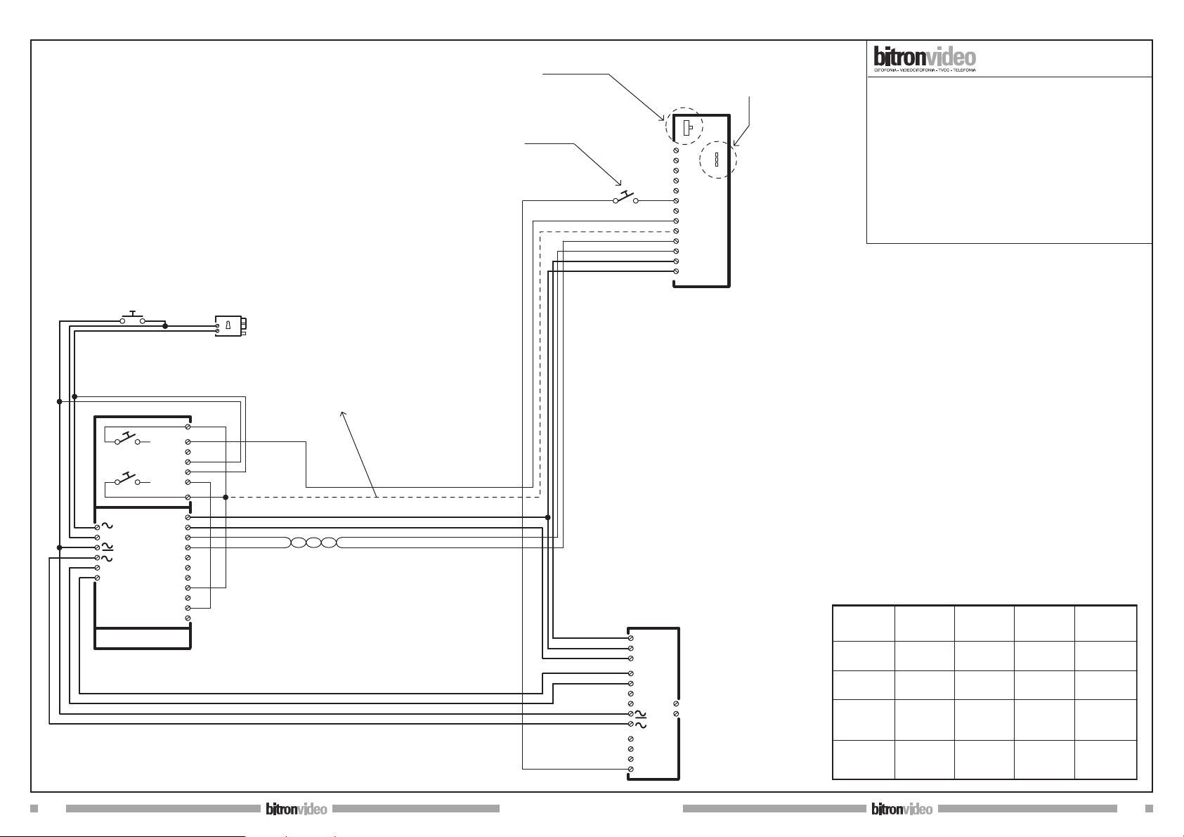
IMPIANTO VIDEOCITOFONICO (SISTEMA “5 FILI”)
CON 1 POSTO ESTERNO, 1 UTENTE
(+ CHIAMATA ELETTRONICA AL PIANO)
“5 WIRES”VIDEO DOORPHONE SYSTEM,
WITH 1 VISITOR PANEL, 1 USER
(+ ELECTRONIC CALL AT THE FLOOR)
SISTEME VIDEO A “5 FILS”,
AVEC 1 PLATINE, 1 FAMILLE
(+ APPEL ELECTRONIQUE A L’ETAGE)
CH
+
Ap
_
1
3
A
CD
B
9
CP
V
S
0
P1
P2
L
L
CD 1-2
( GVM 70/1 )AN 6082/L
1
_
+
3C
3M
0
230
D
R
NA
NC
N
P
( A 70/IRC )
AV 7362
H
segreto
off
J1
1
3
B
A
E
C
T
P
LD
Q2
L
SW1
Q1
Q2
Q1
AV 1423/001
AV 1423/010 +
Selettore impedenza su "L"
Selector impedance on"L"
Sélecteur impédance sur "L"
Tasto chiamata al piano
Call button at the floor
Bouton appel palier
Segreto di conversazione "on/off"
Conversation secret "on/off"
Secret de conversation"on/off"
eventuale filo di autoeccitazione
possible self-lighting wire
eventuelle fil de autoallumage
doppino twistato
twisted pair
couple tressés
serratura
lock
serrure
Apriporta esterno
External door opener
Bouton de sortie
RETE
MAINS
SECTEUR
Distanza
Distance
mt.
50
100
200
Tabella Sezioni Conduttori
Wire section
Section conducteur
Filo/Wire
1/3
mm2
0,75
1,50
2,50
Filo/Wire
C/E/T/P
mm2
0,50
0,75
1,00
Filo/Wire
A-B
mm2
0,30
0,30
twisted
0,30
twisted
Filo/Wire
+/-/al/al-
mm2
1,50
10
012175867.00 012175867.00
11
All rights reserved - Diritti riservati a Norma di Legge
175 946 70/A
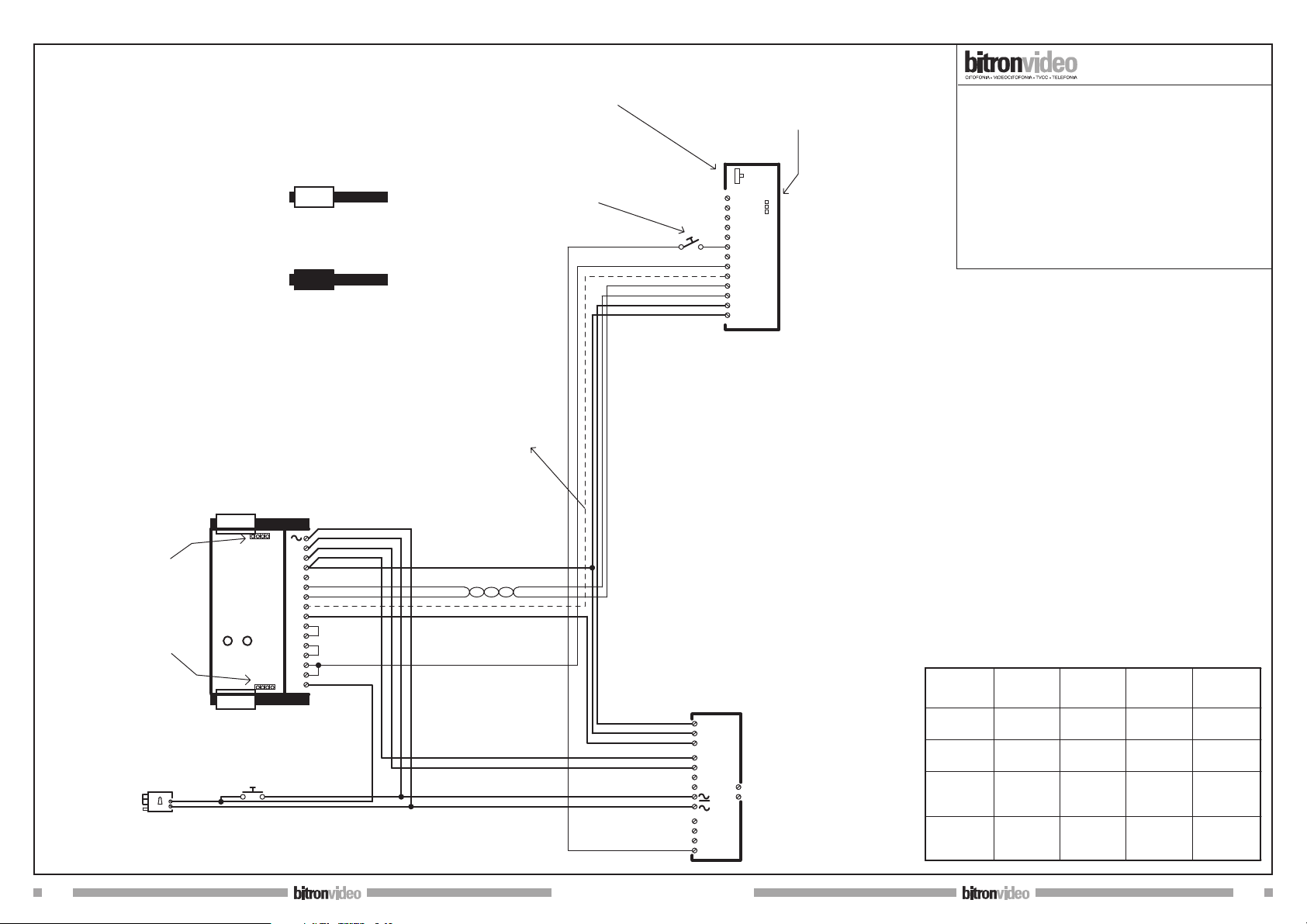
IMPIANTO VIDEOCITOFONICO (SISTEMA “5 FILI”)
CON 1 POSTO ESTERNO, 1 UTENTE
(+ CHIAMATA ELETTRONICA AL PIANO)
“5 WIRES”VIDEO DOORPHONE SYSTEM,
WITH 1 VISITOR PANEL, 1 USER
(+ ELECTRONIC CALL AT THE FLOOR)
SISTEME VIDEO A “5 FILS”,
AVEC 1 PLATINE, 1 FAMILLE
(+ APPEL ELECTRONIQUE A L’ETAGE)
doppino twistato twisted pair
couple tressés
AP CL
SC RC
IntEst
0
+
AP
C1
C2
CD
X
CP
Y
3
E
B
A
CH
1/
_
GAVM 3000
AV 0060/00
1
_
+
3C
3M
0
230
D
R
NA
NC
N
P
( A 70/IRC )
AV 7362
H
segreto
off
J1
1
3
B
A
E
C
T
P
LD
Q2
L
SW1
Q1
Q2
Q1
AV 1423/001
AV 1423/010 +
Selettore impedenza su "L"
Selector impedance on"L"
Sélecteur impédance sur "L"
Tasto chiamata al piano
Call button at the floor
Bouton appel palier
Segreto di conversazione "on/off"
Conversation secret "on/off"
Secret de conversation"on/off"
eventuale filo di autoeccitazione
possible self-lighting wire
eventuelle fil de autoallumage
serratura
lock
serrure
RETE
MAINS
SECTEUR
Apriporta esterno
External door opener
Bouton de sortie
Connettore di Chiusura
Senza Collegamenti
Connettore di Chiusura
Senza Collegamenti
Connettore Bus con collegamenti
BUS Connector with connection
Connecteur BUS avec connections
Connettore di Chiusura senza collegamenti
Closure Connector without connection
Connecteur Fermeture sans connections
PER LA FUNZIONE DEI PONTICELLI
VEDI MANUALE ISTRUZIONI
FOR JUMPERS' FUNCTION
SEE THE INSTRUCTIONS MANUAL
POUR LA FUNCTION DES PONTETS
VOIR LE MANUEL D'ISTRUCTIONS
Distanza
Distance
mt.
50
100
200
Tabella Sezioni Conduttori
Wire section
Section conducteur
Filo/Wire
1/3
mm2
0,75
1,50
2,50
Filo/Wire
C/E/T/P
mm2
0,50
0,75
1,00
Filo/Wire
+/-/al/al-
mm2
1,50
Filo/Wire
A-B
mm2
0,30
0,30
twisted
0,30
twisted
Table of contents
Languages:
Other Bitron Video TV Mount manuals

Popular TV Mount manuals by other brands

Sanus
Sanus Sanus VisionMount MD115-G1 Brochure & specs

Behringer
Behringer POWERPLAY 16 P16-MB quick start guide

PEERLESS Mounts
PEERLESS Mounts SUF650P Installation and assembly

Metra Electronics
Metra Electronics 99-7614 installation instructions

ricoo
ricoo N4564 quick start guide

Kanto
Kanto MTM65 user manual


