Seura SC-1 User manual

OUTDOOR TV
CEILING MOUNT
INSTALLATION GUIDE
Model Numbers:
SC-1
LC-1
1415
16
" FULLY COLLAPSED
22-15/16" FULLY EXTENDED
17
15
16
"
25mm
1"
5
16
" X
13
16
"
4
1
8
"
4
7
8
"
5"
5
3
4
"
6
1
2
"
6
1
2
"
4
5
16
"
297
16
" FULLY COLLAPSED
51-7/16" FULLY EXTENDED
17
15
16
"
25mm
1"
4
5
16
"
17
15
16
"
25mm
1"
Optional: Us ing the keyhole loc ations, drill
the additiona l holes for the sup port screws.
Insert and fa sten two screws w ithout
washers until approximately 1/2" remains.
O
p
t
i
o
n
a
l
K
e
y
h
o
l
e
S
l
o
t
O
p
t
i
o
n
a
l
K
e
y
h
o
l
e
S
l
o
t
WARRANTY REGISTRATION
REGISTER FOR
EXTRA BENEFITS
Activate within 30 days of purchase:
seura.com/activate

2
Prior to the installation of this product, read all
instructions. Keep this manual for future reference.
This product is designed to mount televisions
and any accessories weighing up to 220 lbs. to a
properly rated ceiling structure.
CAUTION DO NOT EXCEED MAXIMUM LISTED
WEIGHT CAPACITY. SERIOUS INJURY OR PROPERTY
DAMAGE MAY OCCUR.
Warnings:
• Safety measures must be practiced at all times
during the assembly of this product. Use proper
safety equipment and tools for the assembly
procedure to prevent personal injury.
• At least two qualied people should perform the
assembly procedure. Proper installation must
be followed as outlined in these installation
instructions. Personal injury and/or property
damage can result from dropping or mishandling
the TV.
• Ensure that there are no missing or defective
parts upon receipt. Never use defective parts.
• This product contains small parts that could be
a choking hazard.
• The ceiling you ax the Séura mount to must
be capable of supporting ve times the weight
of the television and the mount combined. A
professional installer or structural engineer
should inspect or verify the requirements.
• Do not use this product for any purpose other
than to mount a VESA compliant TV on a vertical
surface as outlined in this manual.
• When mounting to metal structures or concrete
ceilings, an alternative anchor (not included)
should used.
• Always inspect mounting location for electrical
wires, water, and natural gas lines prior to
installation. Cutting or drilling into these utility
lines may cause serious personal injury or
property damage.
• Do not install near sources of high heat.
• Do not install on a structure that is prone to
vibration, movement or chance of impact.
Note: The included hardware is for mounting to
vertical concrete surfaces or wood trusses and
ceiling structures. If you are uncertain about the
nature of your structure, please consult your
hardware or installation professional for proper
mounting to types of structures.
Safety
Compatible with Séura Outdoor TVs:
Pair with any Séura Outdoor TV 42″ – 86″ or any other compatible display not surpassing a maximum weight
limit of 220 lbs. Compatible with VESA mount patterns up to 600×400.
WARNING: Cancer and Reproductive
Harm: www.p65warnings.ca.gov.
3
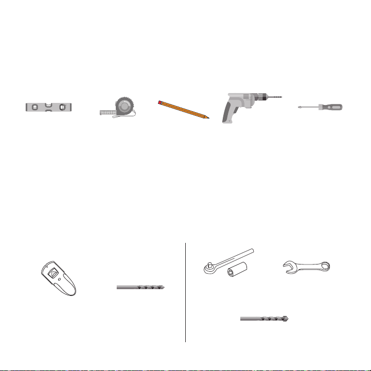
Parts and Tools Required (not included)
The following tools may be required depending on your particular installation. They are not included.
P5080T
Installation Instructions Visit the Premier Mounts website at http://www.premiermounts.com Page 3
Parts List
Installation Tools
The following tools may be required depending upon your particular installation. They are not included.
Pencil Level
¼˝ Drill Bit for
Wood Stud
Electronic Stud Finder
Socket Wrench Phillips Tip Screwdriver
Tape Measure
Hand Held Drill
Hammer**
3/8˝ Concrete Drill Bit*
Protective Eyewear
* Optional tools for concrete installations.
½˝ Socket M10 Socket*
2
1
5/16˝ x 3˝ Lag Bolts
(Qty 6)
Thread Depth Indicator
(Qty 1)
Universal Spacers
Finned Anchors
(Qty 6)
(Qty 24)
5/16˝ Flat Washers
(Qty 6)
Pro Mounting Hardware
Universal Washers
(Qty 6)
Security Barrel
(Qty 1)
Wall Plate
(Qty 1)
Universal Tilt Brackets
(Qty 2)
M6 x 60mm Screws
(Qty 2)
1/2”
1/2”
1/2”
1/2”
Level
Stud Sensor
(edge-to-edge stud
nder is recommended)
Tape Measure
7/32″ Drill Bit
7/16″ Masonry Drill Bit
Socket Wrench
½″ Socket
½″ Combination
Wrench
Pencil Power Drill Philips #2
Screwdriver
(6mm Allen Wrench
for use with 86″
Ultra Bright TV size)
For Wood Truss Installation For Concrete, Brick and Stone Installation
1/2”
1/2”
1/2”
1/2”
1/2”
4
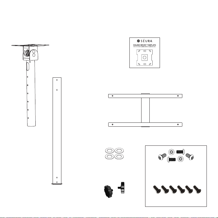
Ceiling Bracket
Ceiling Bracket
Extension
(length varies by model)
Mounting Plate Rails
Parts Included
Before using the device, please check the following contents of the box for completeness. Illustrations are
not to scale. If any parts are missing or damaged, contact Séura.
Mounting Template
(located on inside bottom of box)
1415
16
" FULLY COLLAPSED
22-15/16" FULLY EXTENDED
17
15
16
"
25mm
1"
5
16
" X
13
16
"
4
1
8
"
4
7
8
"
5"
5
3
4
"
6
1
2
"
6
1
2
"
4
5
16
"
297
16
" FULLY COLLAPSED
51-7/16" FULLY EXTENDED
17
15
16
"
25mm
1"
4
5
16
"
17
15
16
"
25mm
1"
Optional:U sing the keyhole lo cations, drill
theaddition al holes for the su pport screws.
Insertand f asten two screw s without
washersuntil approximately 1/2" remains.
O
p
t
i
o
n
a
l
K
e
y
h
o
l
e
S
l
o
t
O
p
t
i
o
n
a
l
K
e
y
h
o
l
e
S
l
o
t
1415
16
" FULLY COLLAPSED
22-15/16" FULLY EXTENDED
17
15
16
"
25mm
1"
5
16
" X
13
16
"
4
1
8
"
4
7
8
"
5"
5
3
4
"
6
1
2
"
6
1
2
"
4
5
16
"
297
16
" FULLY COLLAPSED
51-7/16" FULLY EXTENDED
17
15
16
"
25mm
1"
4
5
16
"
17
15
16
"
25mm
1"
Option al: Using the keyho le locations, d rill
the addi tional holes fo r the support scr ews.
Inser t and fasten two s crews without
washers until approximately 1/2" remains.
O
p
t
i
o
n
a
l
K
e
y
h
o
l
e
S
l
o
t
O
p
t
i
o
n
a
l
K
e
y
h
o
l
e
S
l
o
t
1415
16
" FULLY COLLAPSED
22-15/16" FULLY EXTENDED
17
15
16
"
25mm
1"
5
16
" X
13
16
"
4
1
8
"
4
7
8
"
5"
5
3
4
"
6
1
2
"
6
1
2
"
4
5
16
"
297
16
" FULLY COLLAPSED
51-7/16" FULLY EXTENDED
17
15
16
"
25mm
1"
4
5
16
"
17
15
16
"
25mm
1"
Optional : Using the keyhol e locations, dri ll
the addit ional holes for th e support screws .
Insert an d fasten two scr ews without
washers until approximately 1/2" remains.
O
p
t
i
o
n
a
l
K
e
y
h
o
l
e
S
l
o
t
O
p
t
i
o
n
a
l
K
e
y
h
o
l
e
S
l
o
t
1415
16
" FULLY COLLAPSED
22-15/16" FULLY EXTENDED
17
15
16
"
25mm
1"
5
16
" X
13
16
"
4
1
8
"
4
7
8
"
5"
5
3
4
"
6
1
2
"
6
1
2
"
4
5
16
"
297
16
" FULLY COLLAPSED
51-7/16" FULLY EXTENDED
17
15
16
"
25mm
1"
4
5
16
"
17
15
16
"
25mm
1"
Option al: Using the keyho le locations, d rill
the addi tional holes fo r the support scr ews.
Inser t and fasten two s crews without
washers until approximately 1/2" remains.
O
p
t
i
o
n
a
l
K
e
y
h
o
l
e
S
l
o
t
O
p
t
i
o
n
a
l
K
e
y
h
o
l
e
S
l
o
t
(4) 5/16″
Stainless Steel
Flat Washers
P5080T
Installation Instructions Visit the Premier Mounts website at http://www.premiermounts.com Page 3
Parts List
Installation Tools
The following tools may be required depending upon your particular installation. They are not included.
Pencil Level
¼˝ Drill Bit for
Wood Stud
Electronic Stud Finder
Socket Wrench Phillips Tip Screwdriver
Tape Measure
Hand Held Drill
Hammer**
3/8˝ Concrete Drill Bit*
Protective Eyewear
* Optional tools for concrete installations.
½˝ Socket M10 Socket*
2
1
5/16˝ x 3˝ Lag Bolts
(Qty 6)
Thread Depth Indicator
(Qty 1)
Universal Spacers
Finned Anchors
(Qty 6)
(Qty 24)
5/16˝ Flat Washers
(Qty 6)
Pro Mounting Hardware
Universal Washers
(Qty 6)
Security Barrel
(Qty 1)
Wall Plate
(Qty 1)
Universal Tilt Brackets
(Qty 2)
M6 x 60mm Screws
(Qty 2)
(2) 1/4-20 Knobs
44"
17
15
16
"
1"
4
5
16
"
14"
14"
5
13
16
"
5
13
16
"
5
13
16
"
5
13
16
"
1
2
" X 1"
205
16
"
261
4"
14"14"
(6) 1/4-20x1/2 Stainless Steel
Security Torx Screws
(6) 1/4-20x1/2 Black Stainless
Steel Hex Head Screws
44"
17
15
16
"
1"
4
5
16
"
14"
14"
5
13
16
"
5
13
16
"
5
13
16
"
5
13
16
"
1
2
" X 1"
205
16
"
261
4"
14"14"
OR
5
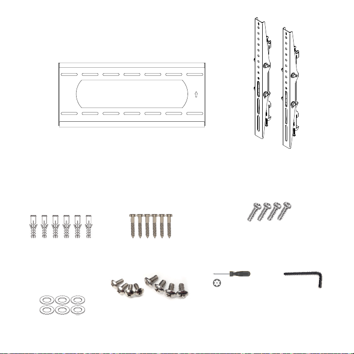
Parts Included, Packaged as TW-5
Mounting Plate
(2) Tilt Mount TV
Brackets
261
4"
20 5
16
"11 716"
25mm
1"
558
"
7"
115
16"
261
4"
20 5
16
"11 716"
25mm
1"
558
"
7"
115
16"
261
4"
20 5
16
"11 716"
25mm
1"
558
"
7"
115
16"
Mounting Tools and Hardware
(6) Stainless Steel Lag
Screws 5/16”, 3” long
(6) Plastic Anchors, 3” long
For concrete, brick, and
stone installation only
(6) Stainless Steel Flat
Washers, 5/16”
(4) M6 and (4) M8
Phillips VESA Screws
Included with some
mount models
(1) 4mm Allen
Wrench
Included with
some mount
models
261
4"
20 5
16
"11 716"
25mm
1"
558
"
7"
115
16"
(1) T27 Security Torx
Screwdriver
Included with some
mount models
(4) Security Torx
T27 x 1.0 x 16mm
Screws
Included with some
mount models

6
1415
16
" FULLY COLLAPSED
22-15/16" FULLY EXTENDED
17
15
16
"
25mm
1"
5
16
" X
13
16
"
4
1
8
"
4
7
8
"
5"
5
3
4
"
6
1
2
"
6
1
2
"
4
5
16
"
297
16
" FULLY COLLAPSED
51-7/16" FULLY EXTENDED
17
15
16
"
25mm
1"
4
5
16
"
17
15
16
"
25mm
1"
Optional: Using t he keyhole l ocations , drill
the additional holes for the s upport sc rews.
Inser t and fas ten two screws without
washers until approximately 1/2" remains.
O
p
t
i
o
n
a
l
K
e
y
h
o
l
e
S
l
o
t
O
p
t
i
o
n
a
l
K
e
y
h
o
l
e
S
l
o
t
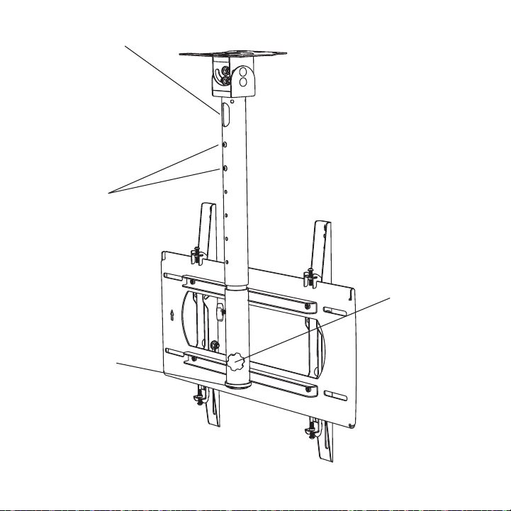
Features
Ceiling
Mounting Plate
A template
with the
mounting hole
pattern is
included to aid
installation. Tilt Locking Bolts
Allows for tilt
angle of the TV
adjustment.
Top Leveling
Screws
Allows for
leveling
adjustments
of the TV after
mounting.
Bottom Locking Screws
Prevents the TV from being
removed or dislodged from
the mounting plate.
Directional
Mounting Arrows
The arrow lets you
know which edge
is up.
7
1415
16
" FULLY COLLAPSED
22-15/16" FULLY EXTENDED
17
15
16
"
25mm
1"
5
16
" X
13
16
"
4
1
8
"
4
7
8
"
5"
5
3
4
"
6
1
2
"
6
1
2
"
4
5
16
"
297
16
" FULLY COLLAPSED
51-7/16" FULLY EXTENDED
17
15
16
"
25mm
1"
4
5
16
"
17
15
16
"
25mm
1"
Optional: Using t he keyhole l ocations , drill
the additional holes for the s upport sc rews.
Inser t and fas ten two screws without
washers until approximately 1/2" remains.
O
p
t
i
o
n
a
l
K
e
y
h
o
l
e
S
l
o
t
O
p
t
i
o
n
a
l
K
e
y
h
o
l
e
S
l
o
t
Height Adjustment
Use both included
screws to set the
desired height.
Cable Pass Through
Run power and content
cables through the back of
the pole or into the ceiling.
The power cord included
with Séura’s Full Sun Series
85-inch Outdoor TV (model
UB4-85) does not t inside
of the mount pole. The cord
must run alongside the pole
and will not be neatly tucked
away inside.
Cable Pass Through
Run power and content
cables through the pole and
connect to the TV inputs.
The power cord included
with Séura’s Full Sun Series
85-inch Outdoor TV (model
UB4-85) does not t inside
of the mount pole. The cord
must run alongside the pole
and will not be neatly tucked
away inside.
Swivel Adjustment
Loosening both knobs
allows adjustment of
the swivel +/- 360°.
Always retighten as TV
may swivel in the wind.
Do not continue to spin
beyond 360° because
cords become wrapped
and could disconnect
from the connections.
8
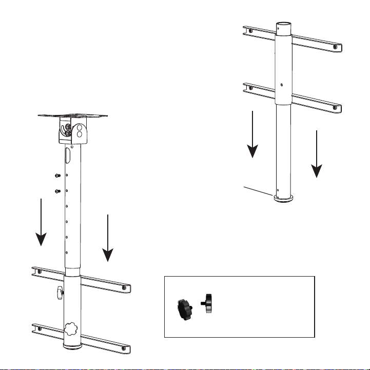
Step 1: Assemble and Prepare Mount
1. Assemble ceiling mount
Ensure the plastic ring is on the Ceiling Bracket Extension. Slide the
Mounting Plate Rails onto the Ceiling Bracket Extension.
Note: The Mounting Plate Rails is a symmetrical part, so orientation
does not matter.
2. Attach the Ceiling Bracket
Slide the Ceiling Bracket Extension into the Ceiling Bracket. Using
two of the included 1/4-20x1/2 security torx screws or two of the
included 1/4-20x1/2 black stainless steel hex head screws, tighten
the extension onto the desired height. Attach two knobs and install
into the plate mount rails.
To adjust the swivel angle
of the TV, loosen the two
thumb screws on the
back of the ceiling mount.
Adjust to the desired angle.
Tighten both screws.
44"
17
15
16
"
1"
4
5
16
"
14"
14"
5
13
16
"
5
13
16
"
5
13
16
"
5
13
16
"
1
2
" X 1"
205
16
"
261
4"
14"14"
Plastic Ring
9
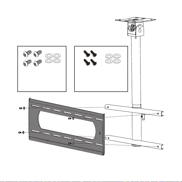
3. Attach mounting plate to ceiling mount
Using four of the included 1/4-20x1/2 security torx screws
or four of the included 1/4-20x1/2 black stainless steel hex
head screws, and four at washers, attach the mounting
plate to the ceiling mount rails as shown.
44"
17
15
16
"
1"
4
5
16
"
14"
14"
5
13
16
"
5
13
16
"
5
13
16
"
5
13
16
"
1
2
" X 1"
205
16
"
261
4"
14"14"
44"
17
15
16
"
1"
4
5
16
"
14"
14"
5
13
16
"
5
13
16
"
5
13
16
"
5
13
16
"
1
2
" X 1"
205
16
"
261
4"
14"14"
44"
17
15
16
"
1"
4
5
16
"
14"
14"
5
13
16
"
5
13
16
"
5
13
16
"
5
13
16
"
1
2
" X 1"
205
16
"
261
4"
14"14"
44"
17
15
16
"
1"
4
5
16
"
14"
14"
5
13
16
"
5
13
16
"
5
13
16
"
5
13
16
"
1
2
" X 1"
205
16
"
261
4"
14"14"
P5080T
Installation Instructions Visit the Premier Mounts website at http://www.premiermounts.com Page 3
Parts List
Installation Tools
The following tools may be required depending upon your particular installation. They are not included.
Pencil Level
¼˝ Drill Bit for
Wood Stud
Electronic Stud Finder
Socket Wrench Phillips Tip Screwdriver
Tape Measure
Hand Held Drill
Hammer**
3/8˝ Concrete Drill Bit*
Protective Eyewear
* Optional tools for concrete installations.
½˝ Socket M10 Socket*
2
1
5/16˝ x 3˝ Lag Bolts
(Qty 6)
Thread Depth Indicator
(Qty 1)
Universal Spacers
Finned Anchors
(Qty 6)
(Qty 24)
5/16˝ Flat Washers
(Qty 6)
Pro Mounting Hardware
Universal Washers
(Qty 6)
Security Barrel
(Qty 1)
Wall Plate
(Qty 1)
Universal Tilt Brackets
(Qty 2)
M6 x 60mm Screws
(Qty 2)
(4) 1/4-20x1/2 Black Stainless
Steel Hex Head Screws
(4) 1/4-20x1/2 Stainless Steel
Security Torx Screws
(4) 5/16” Stainless Steel Flat
Washers (4) 5/16” Stainless Steel Flat
Washers
OR
10
Installation
IMPORTANT: THIS PRODUCT MUST BE MOUNTED TO A PROPERLY RATED CEILING STRUCTURE. The structure
must be able to support ve times the weight of the television and the mount combined. A professional
installer or structural engineer should inspect or verify the requirements of the structure.
CEILING MOUNT TEMPLATE
Refer to the included Installation Guide for complete instruc tions
Optional: Usin g the keyhole loca tions, drill
the additional h oles for the suppo rt screws.
Insert and fas ten two screws wit hout
washers until approximately 1/2" remains.
O
p
t
i
o
n
a
l
K
e
y
h
o
l
e
S
l
o
t
O
p
t
i
o
n
a
l
K
e
y
h
o
l
e
S
l
o
t
IMPORTANT: HANDLE THE TV IN A VERTICAL POSITION TO AVOID DAMAGE TO THE
SCREEN. IF PLACING THE TV SCREEN-SIDE DOWN OR LEANING AGAINST A WALL DURING
INSTALLATION, COVER THE SCREEN WITH A PROTECTIVE CLOTH OR BLANKET.
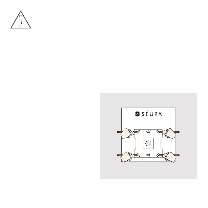
Step 2: Mount Ceiling Plate to Ceiling
1. Choose mounting location
Place the template in the desired location on
the ceiling.
Wood Joist/Truss Mounting:
At least four hole locations must be fastened
to joists/trusses or an appropriately stabilized
structure. Verify the center of the wood beam
using an edge-to-edge stud nder. Mark all hole
locations in the template slots with a pencil on
the ceiling.
Concrete, Stone or Brick:
All six hole locations must be fastened. Mark
all hole locations in the template slots with a
pencil on the ceiling.

11
CEILING MOUNT TEMPLATE
Refer to the included Installation Guide for complete instruc tions
Optional: Using the keyhole loc ations, drill
the additional h oles for the suppo rt screws.
Insert and fas ten two screws wit hout
washers until approximately 1/2" remains.
O
p
t
i
o
n
a
l
K
e
y
h
o
l
e
S
l
o
t
O
p
t
i
o
n
a
l
K
e
y
h
o
l
e
S
l
o
t
2. Drill pilot holes
Wood Joist/Truss Mounting:
Pre-drill the four marked holes 3-inches deep with a 7/32″ drill bit.
Concrete:
Pre-drill the six marked holes 3-inches deep with a 7/16″ masonry drill bit. Insert a plastic anchor into each
of these holes. If necessary, lightly tap each anchor into place with a hammer.
Optional for
Wood Joist/Truss
Mounting: Using the
keyhole locations,
drill the additional
holes for the
support screws.
Insert and fasten
two 5/16″, 3″ long
lag screws without
washers until
approximately 1/2″
remains.
O
p
t
i
o
n
a
l
K
e
y
h
o
l
e
S
l
o
t

12
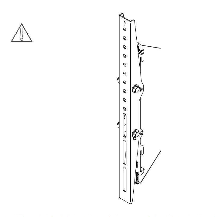
3. Attach ceiling mounting plate
Align the mounting plate with the pre-drilled holes. Ensure that the cable pass through holes on the
mount are positioned appropriately.
Align the bracket with the screw keyed slots and
turn to hold in place. Finish tightening all 5/16″,
3″ long lag screws with at washers until they
are snug with the mounting surface. Do not over
tighten the lag screws. Tighten the lag screws only
until the washers are pulled rmly against the
bracket.
Align the bracket with the pre-drilled holes. Attach
bracket to the ceiling using the six 5/16″, 3″ long
lag screws and six at washers. Tighten all lag
screws using a socket wrench and ½″ socket.
Make sure the anchor is seated completely ush
with the concrete surface even if there is another
layer of material, such as drywall. Do not over
tighten the lag screws. Tighten the lag screws only
until the washers are pulled rmly against the
bracket.

13
Step 3: Attach Tilt Mount TV Brackets to TV
IMPORTANT: Check your TV manual before attaching mount brackets
to TV. Some models require attaching soundbar brackets in tandem
with attaching mount brackets.
Using a Philips #2 Screwdriver (or 6 mm Allen Wrench for 86” Ultra
Bright TV), remove the four VESA mount screws from the back of
the TV. Place the two identical Tilt Mount TV Brackets at against
the back of the TV with the arrows pointed towards the top of the
TV. Line the brackets up with the VESA mount fastener locations. If
mounting a Séura Outdoor TV (49-inch to 86-inch display sizes), use
the second hole down from the top on each Tilt Mount TV Bracket. If
mounting a Séura Outdoor TV model SHD2-43, then use the top hole
on each Tilt Mount TV Bracket. Attach the Tilt Mount TV Brackets to
the TV using the same four VESA mount screws that you just removed.
261
4"
20 5
16
"11 716"
25mm
1"
558
"
7"
115
16"
Note: If installing with a soundbar
or if the TV’s VESA screws are
not long enough to attach the Tilt
Mount TV Brackets, then use the
four included Security Torx T27
x 1.0 x 16mm Screws or the four
included M6 or M8 Philips VESA
screws that are slightly longer than
the TV’s factory screws.
Shade Series
TV 55″ 65″ 75″
Screw Size M6 M6 M8
Full Sun Series
TV 50″ 65″ 85″
Screw Size M8 M8 M8
Note: Security Torx Screws (available with some mount
models) provide additional security to attach the brackets
to the TV. Installers may opt to use these in place of the
TV’s VESA screws, even if longer screws are not needed to
accommodate a soundbar bracket or mount brackets.

14
Step 4: Hang the TV and Connect Power and Content Cables
IMPORTANT: NEVER TRY TO HANG A TV BY YOURSELF. ALWAYS USE AT LEAST TWO PEOPLE TO LIFT THE TV
INTO PLACE.
1. Lift the TV and bring the back of the TV towards
the mount, positioning it slightly above the
mounting plate.
2. Lower the TV to hook the bottom hooks of the
Tilt Mount TV Brackets on the lower rail of the
mounting plate.
3. Bring the top of the TV closer to the mount to
hook the top hooks of the Tilt Mount TV Brackets
on the top rail of the mounting plate.
4. Make sure the bottom and top rails are fully
engaged.
Do not let go of the TV until you are certain that the
top and bottom hooks of both mounting brackets
are securely engaged on the upper and lower
mounting rails of the mounting plate.
5. Connect power and make connections to TV
inputs. Cords can be routed through the oor
stand pole so they are out of sight. The power
cord included with Séura’s Full Sun Series 85-inch
Outdoor TV (model UB4-85) does not t inside of
the mount pole. The cord must run alongside the
pole and will not be neatly tucked away inside.
15
Top Leveling Screw
Allows for leveling
adjustments of the TV
after mounting.
Bottom Locking Screw
Prevents the TV from
being removed or
dislodged from the
mounting plate.
Step 5: Adjust the TV
Séura recommends checking knobs, screws, and bolts
every two to six months. Temperature uctuations,
wind, and normal wear and tear can loosen hardware
over time.
Top leveling screw adjustment:
If your TV is not level, the two (2) top leveling screws
located on the top of the tilt mount TV brackets will
allow you to compensate for this tilt by adjusting
the screws with the provided T27 security torx
screwdriver or 4mm Allen wrench.
1. Loosen both leveling screws (one on each bracket).
2. Adjust the tilt of your TV.
3. Tighten both leveling screws.
Do not overtighten the leveling screws.
Bottom locking screw adjustment:
After you have adjusted leveling the TV, tighten the
two (2) bottom locking screws located on the bottom
of the tilt mount TV brackets (one on each bracket)
using the provided T27 security torx screwdriver or
4mm Allen wrench.
Do not overtighten the locking screws.
261
4"
20 5
16
"11 716"
25mm
1"
558
"
7"
115
16"
Caution: It is possible to dislodge
your TV while you level it. Use
extreme caution until you tighten the
leveling and locking screws.
16
P5080T
Installation Instructions Visit the Premier Mounts website at http://www.premiermounts.com Page 15
Leveling Screw Adjustment
If your at panel is tilted too far to one side, the leveling
screws will allow you to compensate for this tilt by
adjusting the screws with a screwdriver.
Loosen both locking screws.
® Adjust the tilt of your at panel.
¯ Tighten both locking screws.
Caution!
It is possible to dislodge your at panel while you
level your at panel. Use extreme caution until
you tighten the locking screws.
Mounting Bracket Adjustments
Locking Screw Adjustment
After you have nished leveling your at panel, be sure
to tighten the two (2) M6 x 120mm locking screws.
Do not overtighten the locking screws.
M6 x 120mm
Locking Screw
(1 per Bracket)
M6 x 30mm
Leveling Screw
(1 per Bracket)
Tilt Adjustment
Adjusting the Flat Panel Friction Tilt Angle
Place one hand at the center-top edge of the at
panel.
® Place the other hand on the center-bottom edge of
the at panel.
¯ Using the upper hand, gently pull the top of the
at panel towards you while the lower hand gently
pushes the bottom of the at panel away from you.
Adjusting the Flat Panel to the Original Position
Place one hand at the center-top edge of the at
panel.
® Place the other hand on the center-bottom edge of
the at panel.
¯ Using the upper hand, gently push the top of the at
panel towards the wall while the lower hand gently
pulls the bottom of the at panel away from the wall.
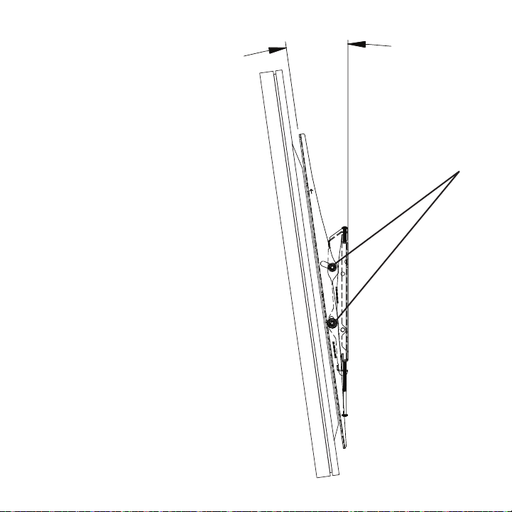
Tilt adjustment:
Adjusting the TV Tilt Angle
1. Place one hand on the center-top edge
of the TV.
2. Place the other hand on the center-
bottom edge of the TV.
3. Using the upper hand, gently pull the top
of the TV towards you while the lower
hand gently pushes the bottom of the TV
away from you.
Adjusting the TV to the Original Position
1. Place one hand on the center-top edge
of the TV.
2. Place the other hand on the center-
bottom edge of the TV.
3. Using the upper hand, gently push the
top of the TV towards the back while the
lower hand gently pulls the bottom of the
TV away from the back.
After tilt is adjusted to the desired position,
tighten the (2) tilt locking bolts on each
bracket until the brackets are rmly secured.
Do not overtighten the tilt locking bolts.
Tilt
Locking
Bolts
17
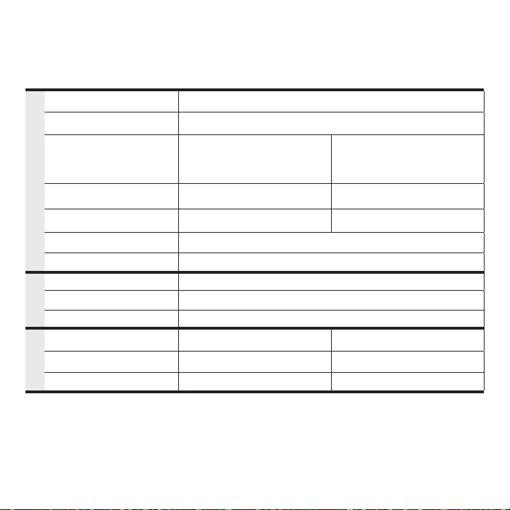
Specications
SHORT ARM CEILING
MOUNT
Model: SC-1
LONG ARM CEILING
MOUNT
Model: LC-1
GENERAL
DISPLAY COMPATIBILITY 42″ - 86″ Séura Outdoor TVs*
VESA COMPATIBILITY Compatible with VESA mount patterns up to 600×400
CUSTOMIZABLE VIEWING
Swivel 360° / - 360°
Extend from 28.5″ to 36.5″ (in
2″ increments) from ceiling to
lower mounting plate rail
Swivel 360° / - 360°
Extend from 43″ to 65″ (in
2″ increments) from ceiling
to lower mounting plate rail
CEILING MOUNT DIMENSIONS Collapsed: 26.25″ w x 6.6 d x 34″ h
Extended: 26.25″ w x 6.6 d x 42″ h
Collapsed: 26.25″ w x 6.6 d x 48.5″ h
Extended: 26.25″ w x 6.6 d x 70.5″ h
MOUNTING PLATE
DIMENSIONS 6.5″ w x 6.5″ h 6.5″ w x 6.5″ h
FINISH COLOR Black Powder Coat
DURABILITY Acrylic E-Coated Steel
INSTALLATION
MAXIMUM WEIGHT LIMIT 220 lbs
INSTALLATION SURFACE Wood / Concrete / Steel
HARDWARE Stainless Steel
SHIPPING
SHIPPING CONTAINER DIMS 19″ w x 27″ l x 5.25″ h 19″ w x 36.5″ l x 5.25″ h
SHIPPING WEIGHT 30 lbs 36 lbs
PRODUCT WEIGHT 24 lbs 30 lbs
Maximum Weight Limit: 220 lbs.
The mounting structure must be capable of supporting at least ve times the weight of the TV. If not, the
structure must be reinforced.
* The power cord included with Séura’s Full Sun Series 85-inch Outdoor TV (model UB4-85) does not t
inside of the ceiling mount pole. The cord must run alongside the pole and will not be neatly tucked away.

18
1415
16
" FULLY COLLAPSED
22-15/16" FULLY EXTENDED
17
15
16
"
25mm
1"
5
16
" X
13
16
"
4
1
8
"
4
7
8
"
5"
5
3
4
"
6
1
2
"
6
1
2
"
4
5
16
"
297
16
" FULLY COLLAPSED
51-7/16" FULLY EXTENDED
17
15
16
"
25mm
1"
4
5
16
"
17
15
16
"
25mm
1"
Optiona l: Using the keyhol e locations, dr ill
the addit ional holes for t he support screw s.
Insert a nd fasten two sc rews without
washers until approximately 1/2" remains.
O
p
t
i
o
n
a
l
K
e
y
h
o
l
e
S
l
o
t
O
p
t
i
o
n
a
l
K
e
y
h
o
l
e
S
l
o
t
SHORT ARM
CEILING MOUNT
Model: SC-1
LONG ARM
CEILING MOUNT
Model: LC-1

19
Ceiling Mount Template Dimensions
www.seura.com
1.800.95.SEURA
PH. 920.857.9069
FAX 920.857.9490
297
16
" FULLY COMPRESSED
51-7/16" FULLY EXTENDED
17
15
16
"
25mm
1"
4
5
16
"
1
6
1
2
"
6
1
2
"
5
3
4
"
5"
5
16
" X
13
16
"
4
1
8
"
4
7
8
"
ITEM
PART NUMBER
REV
DESCRIPTION
QTY
1
25-060514
0
LONG ARM CEILING MOUNT TOP POLE
1
2
25-060515
1
LONG ARM CEILING MOUNT SLIDE
1
3
25-060512
1
OUTDOOR TV MOUNT; MOUNTING PLATE SWIVEL MOUNT
1
4
83-060400
1
TW-5; OUTDOOR TILTING WALL MOUNT
1
5
13-060508
0
OUTDOOR TV MOUNT; BUSHING
1
6
25-060513
1
CEILING MOUNT SWIVEL PLATE
1
7
11-032007
BOLT,CAR,M8X1.25,20mm,N/A,RAW
4
8
13-060728
N/A
NYLON PLASTIC WASHER; 5/16"; BLACK
8
9
13-060526
N/A
18-8 STAINLESS STEEL 5/16" WASHER
8
10
12-032001
N/A
18-8 STAINLESS STEEL M8 x 1.25 NYLON INSERT LOCKNUT
4
11
11-032001
BHCS,M6X1.0,16mm,N/A,RAW
6
REVISIONS
REV.
DESCRIPTION
DATE
APPROVED
1
UPDATED HARDWARE FORM STANDARD TO METRIC
11/1/2022
B. DRUCKREY
SCALE
REVISION
DESCRIPTION
1:11
A
24 JUN 2020
DRAWN BY
LC-1; OUTDOOR LONG ARM CEILING MOUNT
FINISH
83-060500
SIZE
1
PART NO.
SHEET 1 OF 1
MATERIAL
A. ROHAN
DATE
SURFACE AREA
UNSPECIFIED TOLERANCES
FRACTIONAL:
1/16"
ANGULAR:
0.5
TWO PLACE DECIMAL:
.03"
THREE PLACE DECIMAL:
.015"
LASER CUTS:
.005"
PROPRIETARY AND CONFIDENTIAL
THE INFORMATION CONTAINED IN
THIS DOCUMENT IS THE SOLE
PROPERTY OF THE MANUFACTURER.
ANY REPRODUCTION IN PART, OR
AS A WHOLE, WITHOUT THE
WRITTEN PERMISSION OF
MANUFACTURER, IS PROHIBITED.
2

94-060500
Publish date: December 5, 2022
Information is subject to change without notice.
© 2022 Séura
1230 Ontario Road Green Bay, Wisconsin 54311
1-800-957-3872 contacts@seura.com
www.seura.com
LIMITED PRODUCT WARRANTY
For information regarding Séura’s warranty policy, please visit our website: www.seura.com/warranty. If
the current Séura warranty policy is after your product purchase date, please contact Séura Customer
Support to request warranty documentation from the date of your purchase.
For additional customer support, please contact Séura.
Toll Free: 1-800-957-3872 (Monday - Friday 8:00 am – 4:30 pm, Central Time)
Website: www.seura.com/support
Other manuals for SC-1
1
This manual suits for next models
1
Table of contents
Other Seura TV Mount manuals


