Bitstream HYPERION-105 User manual

Quick start manual, a detailed manual is on the enclosed CD or www.bitstream.com.pl
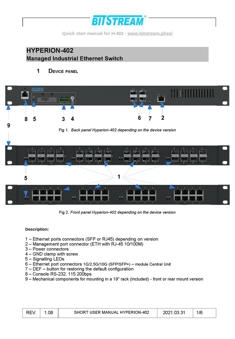
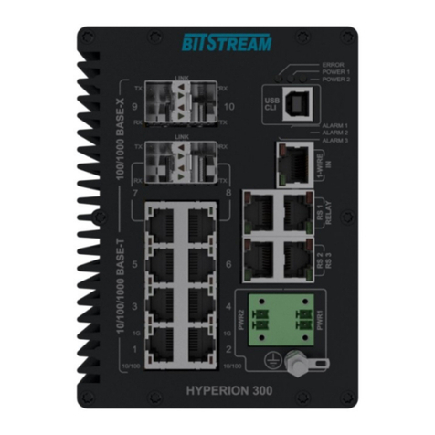
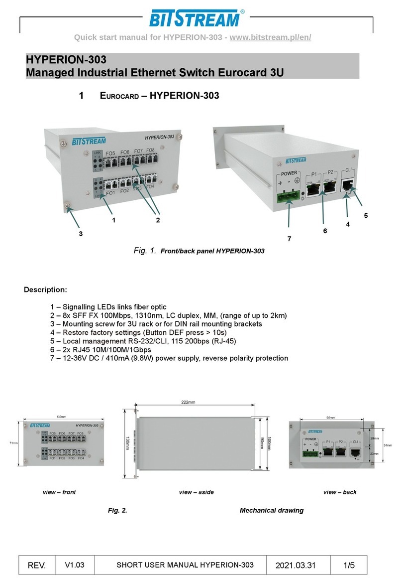
HYPERION-105
Industrial Ethernet Switch
1 FRONT PANEL
Fig 1. Front panel Hyperion-105
1 – clamp with a screw
2 – Power connectors
3 – Ethernet ports – e.g. 8/4x RJ45 + 2/3/4x FP
4 – DEF – button for restoring the default configuration
5 – ignalling LEDs
1 1 Signalling LEDs
Fig 2. Signalling LEDs
POWER – supply on PWR
Y TEM – indicates correct operation of the device
ERROR – signals internal device and system errors
3
2
HORT U ER MANUAL HYPERION-105 1/6REV. 1.14 2021.03.31
1
4
5

Quick start manual, a detailed manual is on the enclosed CD or www.bitstream.com.pl
1.2 Marking
Fig. 3. Code
1.3 Description of device connectors
RJ-45 connectors
Fig 4. The look and num ering of leads in RJ45 connector
HORT U ER MANUAL HYPERION-105 2/6REV. 1.14 2021.03.31

Quick start manual, a detailed manual is on the enclosed CD or www.bitstream.com.pl
The table shows the lay-out of particular signals for RJ-45 connectors.
Status signaling of Ethernet interfaces
Each Ethernet port is equipped with two signaling diodes.
The LED on the left indicates PoE is working:
•green PoE / PoE + with the inserted cable delivered power in PoE (up to 15W) or PoE + (up to 30W)
•yellow PoE ++ with inserted cable supplied power in PoE ++ (60W) or High Power PoE (90W)
standard
•yellow blinking when the cable is removed - force mode (permanently switched on the power supply of
a given port bypassing the PoE standard). After inserting the cable with the PoE receiver on the other
side, the LED lights up green. In this mode, the power delivered to the receiver is limited to 15W per port.
The LED on the right indicates link :
LED Link-act
• LED 10M - yellow link 10Mbps (for activity - blinking)
• LED 100M - green link 100Mbps (for activity - blinking)
I/O interface connector description - (option)
Rys. 1. Appearance and numbering of the I/O connector pins
The arrangement of individual signals for the IO contacts is shown in the table below
HORT U ER MANUAL HYPERION-105 3/6REV. 1.14 2021.03.31
Connector type: RJ-45 (PE1-PE8) Ethernet 10/100Mbit/s
1 (white/orange) RXAn Channel transmitter
2 (orange) RXBn
3 (white/green) TXAn Channel receiver
6 (green) TXBn
IN COM NC1 COM NO1 NC2 COM NO2
Interface Destiny Description of leads
IN Potential free input IN - input contact,
COM - Base contact
OUT1 Relay output 1
NC1 - output normally shorted to COM
NO1 - output normally open to COM
COM - Base contact
OUT2 Relay output 2
NC2- output normally shorted to COM
NO2 - output normally open to COM
COM - Base contact

Quick start manual, a detailed manual is on the enclosed CD or www.bitstream.com.pl
1.4 Description of SFP optical ports
The device has slots for FP modules. The range and type of optical connector depends on the
type of FP insert. FP slots support 100Mbps, 1000Mbps and 2500Mbps.
Range and type of connector depends on the type of FP insert.
Status signaling of SFP optical ports
•External LED – signals transmission link for 1Gbps
•Internal LED – signals transmission link for 100Mbps
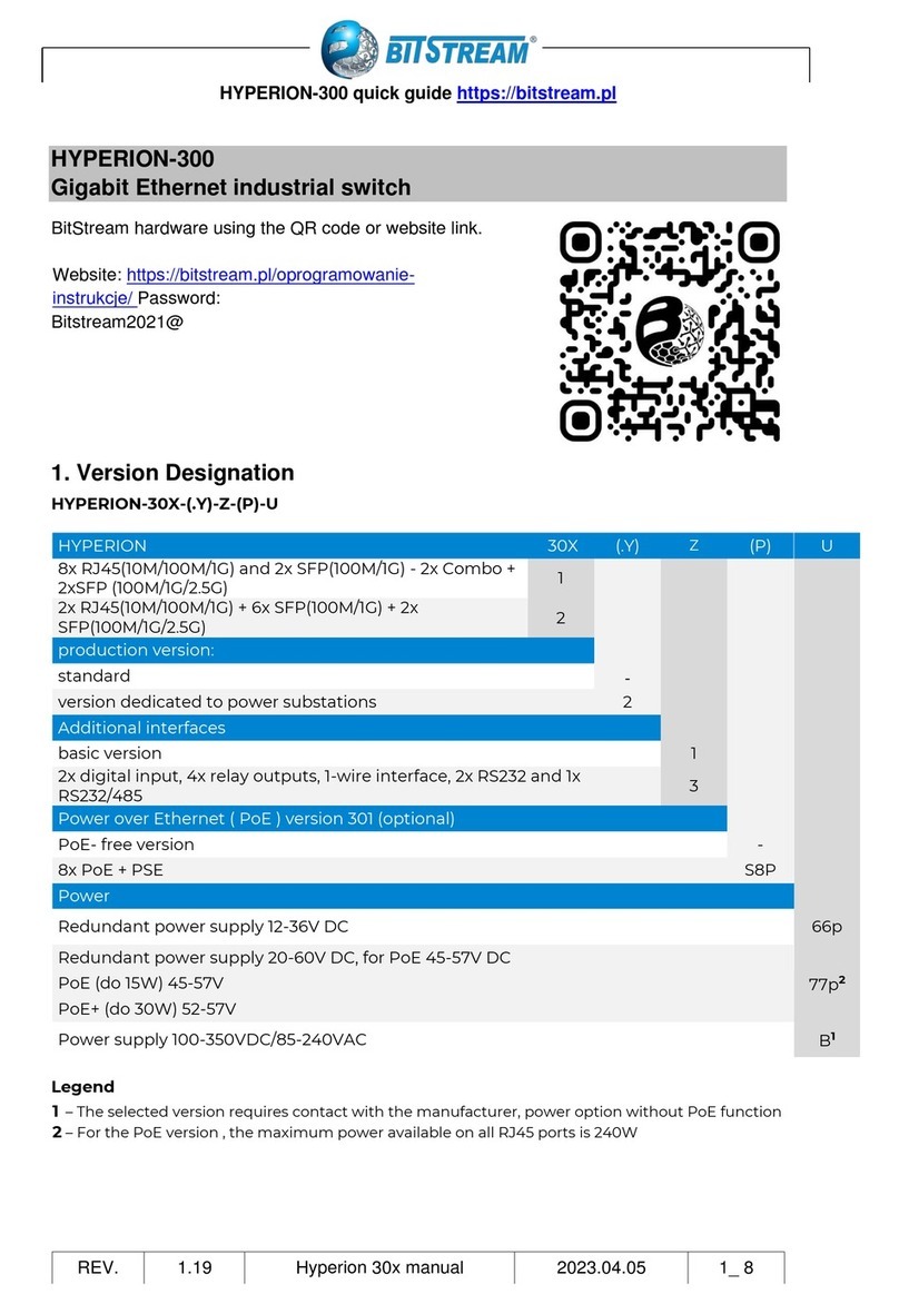
2 POWER SUPPLY
– Two power inputs - redundant
– Voltage range for version 77p 9-60V DC, and for PoE required 45-57V DC
– Current consumption for version 77p 9V/ 800mA and 60V/ 140mA
– Voltage polarity – the polarization on power connector is very important
– crew connection for power supply
3POE POWER SUPPLY (ADDITIONAL OPTION)
– Compliant with the IEEE802.3af standard, IEEE802.3at
– Power available for each port up to 30W or 90W. (depending on the selected version)
– For 55VDC power supply, the maximum total PoE power is 240W
4 FIRST START-UP
After connecting power supply with appropriate parameters to the inputs, the PWR LEDs should
light up green in the beginning. If only one of the power supply inputs is used, only one PWR diode
corresponding to this input will light up. The other LEDs indicate that the device is starting up and is
working properly. The device can be managed via any Ethernet port.
5 DEFAULT PARAMETERS
IP parameters:
Adress: 192.168.0.10 Mask: 0.0.0.0 Gate: 0.0.0.0
User: admin Password: no password
6 MANAGEMENT
The device can be managed and monitored through a web interface using HTTP or HTTP
protocol. Additionally, all management points can be accessed via the command line available via
H or Telnet protocol. The device is also equipped with an NMP agent, which provides MIB
databases containing a lot of data about the current status of the device.
Note!!!: In the indicated models of switches, the firmware update from a version older than:
HYPERION-105 – v120
HYPERION-300 – v120
HYPERION-303 – v120
HYPERION-200 – v308
HYPERION-400 – v308
HYPERION-500 – v308
This will remove passwords for users existing in the configuration (including the "admin"
user)
HORT U ER MANUAL HYPERION-105 4/6REV. 1.14 2021.03.31

Quick start manual, a detailed manual is on the enclosed CD or www.bitstream.com.pl
After the upgrade, the password for each user will be blank the first time they attempt to log in
to management via WWW or CLI
In case of the firmware is downgraded to a version lower than the one indicated above, the
users will be completely removed and a default user "admin" will be created with no password
– empty
7 EMERGENCY RESTORING ACCESS TO THE DEVICE
If the password is lost, there is a mechanism for generating a temporary password to access the
device via www or telnet or CLI. If you enter the password incorrectly five times via telnet or CLI or by
entering the %bitstream% command in the password field, a temporary code will be generated. The
code must be forwarded to the Bit tream upport Department available from 8:00 to 16:00 at
817438643 ext. 28 or sent by e-mail to support@bitstream.pl to receive a temporary 6-hour password
to access the device.
If you cannot log in to the device (due to incorrectly entered configuration e.g.: vlan, etc.), you can
restore the default configuration using the "DEF" button. Holding down the "DEF" button for 5 seconds
will delete the configuration without losing the IP address, and holding down the button for more than
10 seconds will restore the configuration to factory settings.
8 CONFORMITY TO STANDARDS AND RECOMMNEDATIONS
BITSTREAM devices were designed pursuant to obligatory standards and recommendations
in respect of the range of data transmission, electromagnetic compatibility and service safety.
8.1 Electromagnetic compatibility
The device was designed pursuant to the standard EN 55022, EN-55024. BITSTREAM devices are
designated to functioning in closed premises.
Notice: This device is a class A device. In the residential environment may cause radio frequency
interference. In such cases, you can require the user to take appropriate measures.
8.2 afety
In respect to safety of service, BITSTREAM devices were designed and tested for operation safety
along with the EN 60950 standard.
Configuration and installation of the device should be executed by authorised persons familiar with
the service manual. The producer shall not be responsible for any occurrence that could result from
usage and installation that might not conform to this manual.
8.3 Data transmission
The following norms and recommendations determine the functions of data transmission and
communication interface parameters of the device.
• IEEE 802.3u – 100Base-TX Fast Ethernet
• IEEE 802.3u – 100Base-FX Fast Ethernet Fiber
• IEEE 802.3z – Gigabit Fiber
• IEEE 802.1q, p – VLAN mechanisms definitions and signal transmission priorities for Ethernet
network
• IEEE 802.1D-1998 panning Tree Protocol
• IEEE 802.1D-2004 Rapid panning Tree Protocol (R TP)
• IEEE 802.1s Multiple panning Tree Protocol (M TP)
• IEEE 802.3ad Link Aggregation Protocol (LACP)
• IEEE 802.3az EEE
• IEEE 802.3af/at typ 1/2 i PoE++ 90W per port, maximum on all ports up to 240W
ITU K 44 - standard built-in overvoltage protection on RJ45 ports 4kV 10/700us: Resistibility
tests for telecommunication equipment exposed to overvoltages and overcurrents – Basic
Recommendation
HORT U ER MANUAL HYPERION-105 5/6REV. 1.14 2021.03.31

Quick start manual, a detailed manual is on the enclosed CD or www.bitstream.com.pl
9 PACKING COMPLETION OF THE PRODUCT
HORT U ER MANUAL HYPERION-105 6/6REV. 1.14 2021.03.31
1 1 pcs.
2 User manual on CD 1 pcs.
3 hort user manual 1 pcs.
4 Declaration of confirmity 1 pcs.
5 Warranty Card 1 pcs.
6 Holder for DIN rail 1 pcs.
Hyperion-105
Table of contents
Other Bitstream Switch manuals
Popular Switch manuals by other brands

Juniper
Juniper QFX10002 Hardware guide
Extreme Networks
Extreme Networks Summit X150 Series Hardware installation guide

HP
HP ProCurve 2610-48 specification

Extron electronics
Extron electronics MPS 112 Setup guide
Allnet
Allnet ALL4806W user manual
ORiNG
ORiNG TGPS-9084GT-M12X-BP2-24V Quick installation guide
