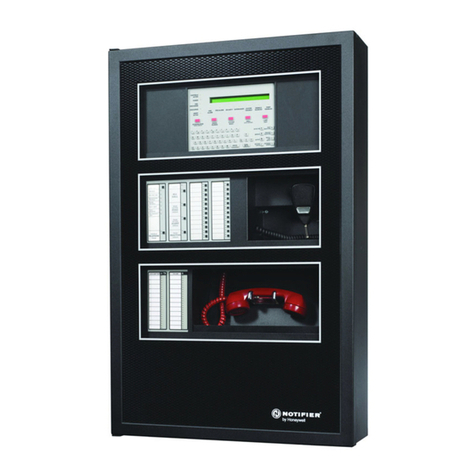
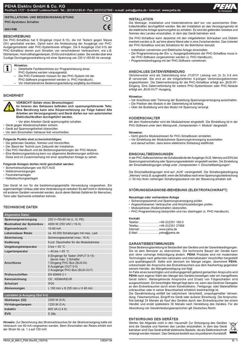
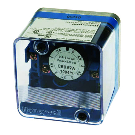
Honeywell 5869 User manual
Other Honeywell Switch manuals
Honeywell
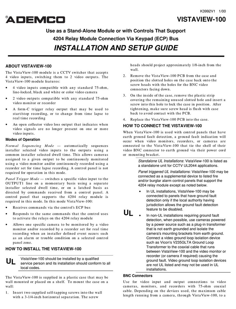
Honeywell Ademco VistaView-100 Assembly instructions
Honeywell
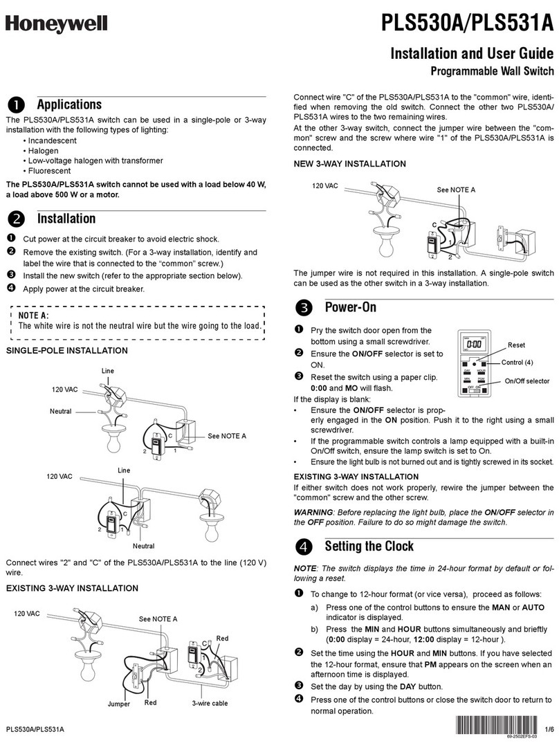
Honeywell PLS531A User manual
Honeywell
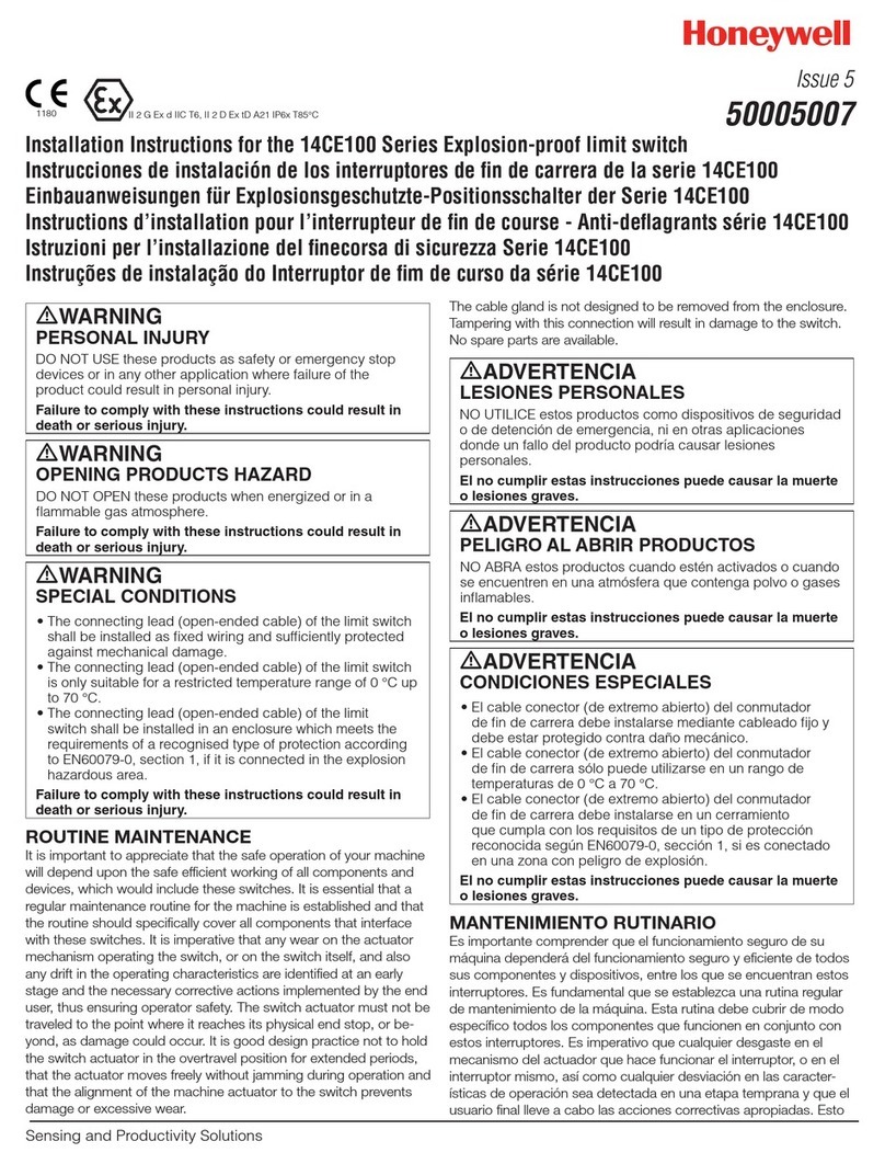
Honeywell 14CE100 Series User manual
Honeywell
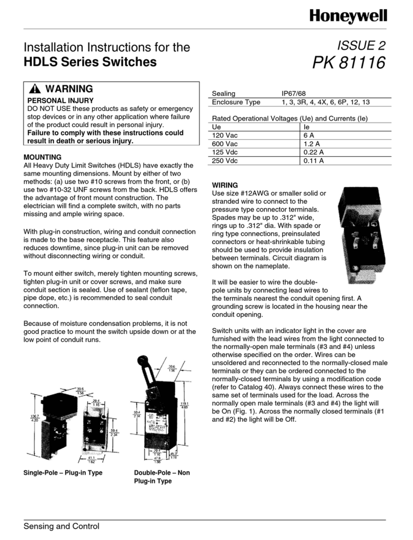
Honeywell HDLS Series Service manual
Honeywell
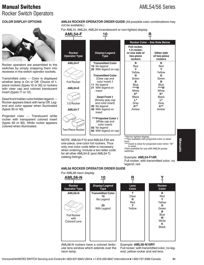
Honeywell AML54 Series User manual
Honeywell
Honeywell MDDS8202 User manual
Honeywell
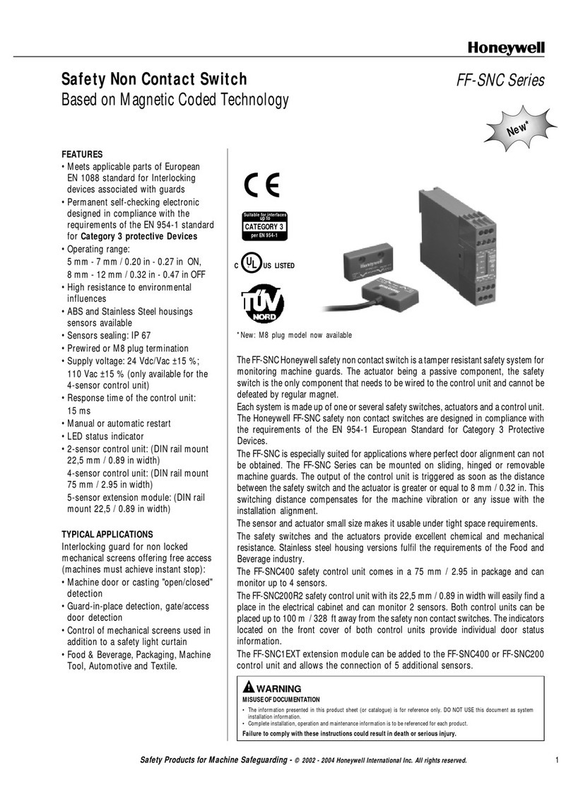
Honeywell FF-SNC User manual
Honeywell
Honeywell Switches User manual
Honeywell
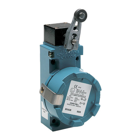
Honeywell BX Series User manual

Honeywell
Honeywell ADEMCO 270R Assembly instructions
Honeywell
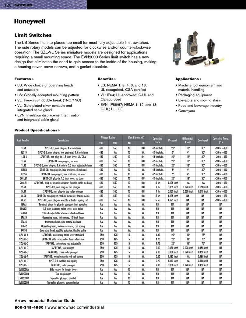
Honeywell EVN2000 Series Installation instructions
Honeywell
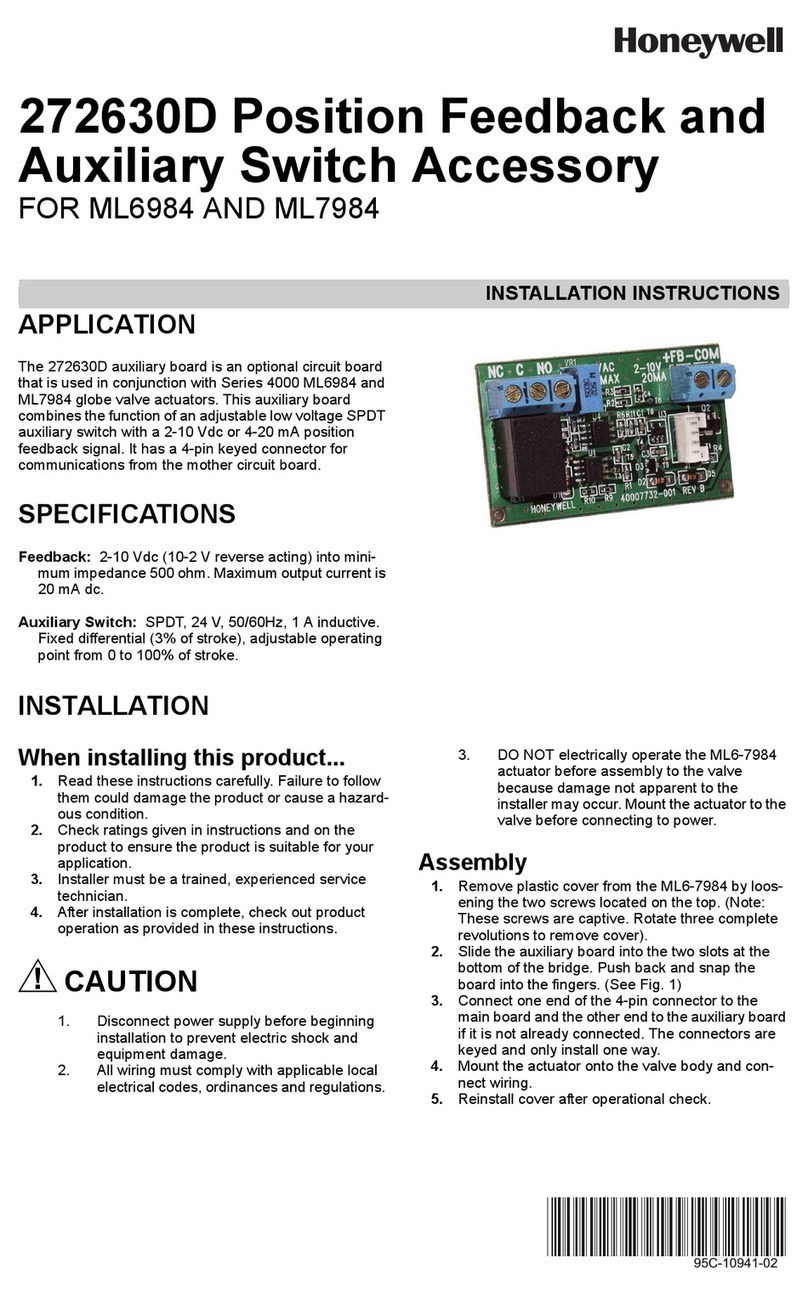
Honeywell 272630D User manual
Honeywell
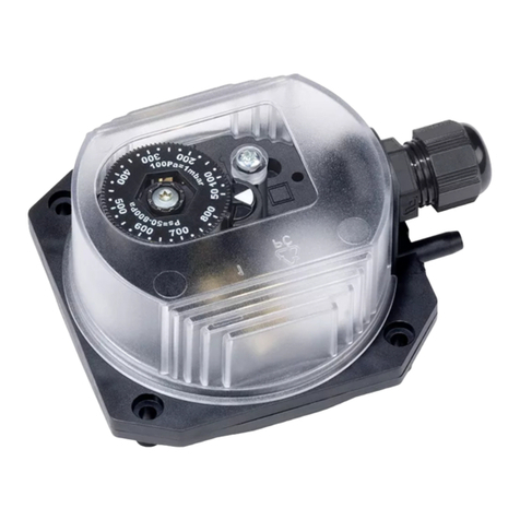
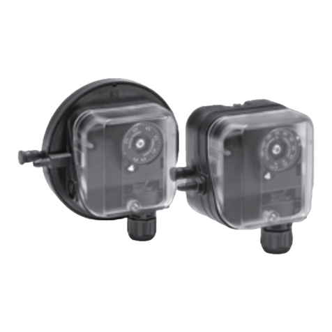
Honeywell krom schroder DL K Series User manual
Honeywell
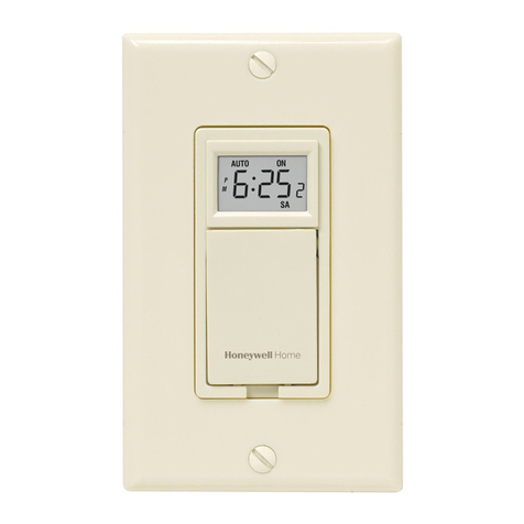
Honeywell PLS730B User manual
Honeywell
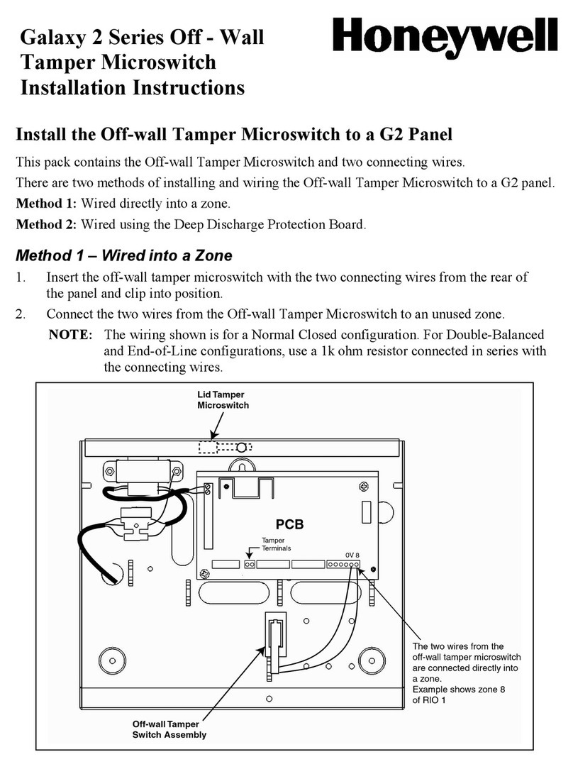
Honeywell Galaxy 2 Series User manual

Honeywell
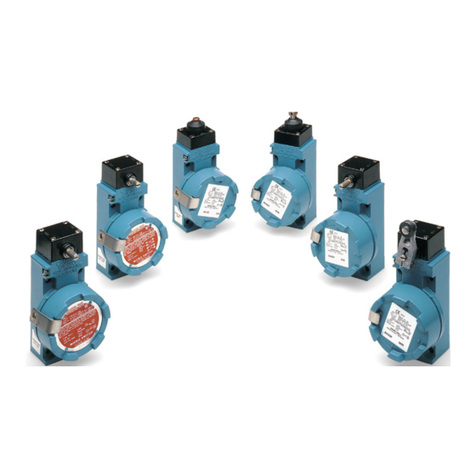
Honeywell WBX Series User manual
Honeywell
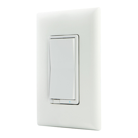
Honeywell ZW4005 User manual
Honeywell
Honeywell PK 80148 User manual
Honeywell
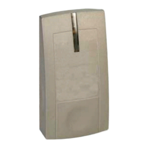
Honeywell IDENT-KEY 3 User manual
Honeywell
Honeywell Krom Schroder DL A Series User manual
