Bitstream HYPERION-300 User manual

HYPERION-300 quick guide https://bitstream.pl
REV.
1.19
Hyperion 30x manual
2023.04.05
1_ 8
HYPERION-300
Gigabit Ethernet industrial switch
BitStream hardware using the QR code or website link.
Website: https://bitstream.pl/oprogramowanie-
instrukcje/ Password:
Bitstream2021@
1. Version Designation
HYPERION-30X-(.Y)-Z-(P)-U
Legend
1–The selected version requires contact with the manufacturer, power option without PoE function
2–For the PoE version , the maximum power available on all RJ45 ports is 240W
HYPERION
30X
(.Y)
Z
(P)
U
8x RJ45(10M/100M/1G) and 2x SFP(100M/1G) - 2x Combo +
2xSFP (100M/1G/2.5G)
1
2x RJ45(10M/100M/1G) + 6x SFP(100M/1G) + 2x
SFP(100M/1G/2.5G)
2
production version:
standard
-
version dedicated to power substations
2
Additional interfaces
basic version
1
2x digital input, 4x relay outputs, 1-wire interface, 2x RS232 and 1x
RS232/485
3
Power over Ethernet ( PoE ) version 301 (optional)
PoE- free version
-
8x PoE + PSE
S8P
Power
Redundant power supply 12-36V DC
66p
Redundant power supply 20-60V DC, for PoE 45-57V DC
77p2
PoE (do 15W) 45-57V
PoE+ (do 30W) 52-57V
Power supply 100-350VDC/85-240VAC
B1

HYPERION-300 quick guide https://bitstream.pl
REV.
1.19
Hyperion 30x manual
2023.04.05
2_ 8
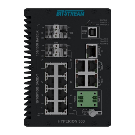
1. Front and rear panel of the device
Fig. 1. Front panel of the device in versions h Hyperion-301-1 and Hyperion-302-1
Fig. 2. Front panel of the device in versions Hyperion-301-3 and Hyperion-302-3
Fig. 3. Rear panel of the device in Hyperion versions
Symbol description:
1 –Ethernet port connectors;
6x RJ45 and 2x RJ45 or 2x SFP - combo ports and 2x SFP 100M/1G/2.5Gb in HYPERION-301-x version
2x RJ45 and 6x SFP and 2x SFP 100M/1G/2.5Gb in HYPERION-302-x version ;
2 –power connectors;
3 –RS-232 console USB connector;
4 –signaling diodes;
1
3
2
5
7
6
8
4
9

HYPERION-300 quick guide https://bitstream.pl
REV.
1.19
Hyperion 30x manual
2023.04.05
3_ 8
5 –1-Wire interface connector and two digital inputs;
6 –relay output connector;
7 –RS232/485 interface connector;
8 –RS232 interface connectors;
9 –DEF button;
1.1 Signaling description
Fig. 1. Signaling diodes.
Designation of signaling diodes :
1 –ERROR: critical alarm indicator;
2 –POWER1: power indicator through connector number 1;3 –POWER2: power indicator through
connector number 2;
4 –ALARM 3: relay output status indicator;
5 –ALARM 2: relay output status indicator;
6 –ALARM 1: alarm indicator;
Ethernet interface status indication
Each Ethernet port is equipped with two signaling LEDs.
1G/s –Ethernet link signaling for 1000Mbit/s throughput.
10/100M/s –Ethernet link signaling for 10/100Mbit/s bit rate.
1.2 Description of electrical connections
The device is equipped with eight RJ45 Ethernet interface ports
Fig. 2. Appearance of the RJ-45 connector
The arrangement of individual signals for RJ-45 connectors is shown in the table.
RJ-45 CONNECTOR (PE1-PE8) Ethernet 10/100Mbit/s
1 - (white and orange.)
RXAn
Channel n transmitter
2 - (orange)
RXBn
3 - (white-green)
TX An
n channel receiver
6 - (green)
TXBn

HYPERION-300 quick guide https://bitstream.pl
REV.
1.19
Hyperion 30x manual
2023.04.05
4_ 8
RJ-45 CONNECTOR (PE1-PE8) Ethernet 1000Mbit/s
1 - (white and orange.)
BI_DA+
Bidirectional contact +A
2 - (orange)
BI_DA-
Bidirectional contact -A
3 - (white-green)
BI_DB+
Bidirectional contact +B
4 - (blue)
BI_DC+
Bidirectional contact +C
5 - (white and blue)
BI_DC-
Bidirectional contact -C
6 - (green)
BI_DB-
Bidirectional contact -B
7 - (white-brown)
BI_DD+
Bidirectional contact +D
8 - (brown)
BI_DD-
Bidirectional contact -D
n –Ethernet channel number
The distribution of signals for serial port connectors is shown in the table below:
RS232 (RS2, RS3) PORT
1
DSR
2
-
3
DTR
4
GND
5
RX
6
TX
7
CTS
8
RTS
PORT RS232/485 (RS1)
1
RS485 RX-
2
RS485 RX+
3
-
4
RS232 GND
5
RS232 RX
6
RS232 TX
7
RS232 CTS/RS485 TX+
8
RS232 RTS/RS485 TX-
PORT RELAY
1
RELAY2 COM
2
RELAY2 NO
3
RELAY1 COM
4
RELAY1 NO
5
RELAY A COM
6
RELAY A NO
7
RELAYB COM
8
RELAY B NO
1-WIRE PORT
1
1-wire interface or T/H sensor data signal
2
Ground
3
3.3V sensor power supply
4
T/H sensor clock signal
5
digital input 1
6
Ground in1
7
digital input 2
8
Ground in2

HYPERION-300 quick guide https://bitstream.pl
REV.
1.19
Hyperion 30x manual
2023.04.05
5_ 8
1.3 Description of SFP optical ports
On the Hyperion-301 version, ports numbered 9 and 10 support SFP modules at speed
100M/1000M/2.5Gbps, and ports 7 and 8 support SFP modules at 100M/1Gbps, which are also
combo ports with two RJ45 electrical ports.
On the Hyperion-302 version, ports 3 and 4 support SFP modules at 100M/1000M/2.5Gbps, and
ports 5, 6, 7, 8, 9, and 10 support SFP modules at 100M/1Gbps.
The range and type of connector depends on the type of SFP insert.
2. Power
•Two power inputs - redundant Power supply range in the version:
►" 66p" –12 -36V DC,
►" 77p" –20-60V DC,
►"B" - 100-350VDC/85-240VAC,
•Current consumption for the 66p version at 12V DC - 850mA and at 36V DC - 300mA, and
for the 77p version 520mA at 20V DC and 180mA at 60V DC (without PoE ).
•Polarity - any for the version without PoE , and for the PoE version according to the figure
below (changing the polarity does not damage the device).
•Screw connection for power supply.
Fig. 4. Appearance of the power connector.
3. POE power supply (option)
•Compliant with IEEE802.3af, IEEE802.3at;
•The device should be powered by 45-57V DC;
•Power available on each RJ45 port does not exceed 30W;
•For 55VDC power supply, the maximum total PoE power is 240W;
•
4. First run
After connecting the power supply with appropriate parameters to the inputs, the PWR LEDs should
light up green at the beginning. If only one of the power inputs is used, only one PWR LED corresponding
to this input will light up. The remaining LEDs indicate device startup and correct operation. The device
can be managed using any Ethernet interface or USB interface through the RS-232 console.
5. Default device parameters
IP parameters:
Address: 192.168.0.10
Mask: 255.255.255.0
Login: admin
Password: no password (empty)

HYPERION-300 quick guide https://bitstream.pl
REV.
1.19
Hyperion 30x manual
2023.04.05
6_ 8
6. Management
Device management uses the HTTP, HTTPS and SNMP protocols and is possible through any
Ethernet port of the device. In addition, access to some device parameters is available via SSH or from
the console level.
The default IP address of the management interface is 192.168.0.10, the default user is "admin", the
default is no password. Drivers for the CLI console available via the USB port are on the CD attached
to the device.
Note!!!: In the indicated switch models, updating the firmware from a version older than:
HYPERION-105 - v120
HYPERION-300 - v120
HYPERION-303 - v120
HYPERION-200 - v308
HYPERION-400 - v308
HYPERION-500 - v308
It will remove the passwords for the existing users in the setup (including the "admin" user).
After updating and restarting, the password will be deleted for each configured user, i.e. the
password field should be left blank when logging in to management via WWW or CLI for the first
time.
In case of downgrading the software to a lower version than indicated in the list above, user
profiles will be completely deleted, and a default "admin" user will be created without a
password.
7. Emergency restore access to the device
In case of password loss, there is a mechanism to generate a temporary password to access the
device via www or telnet or CLI. If you enter the password incorrectly five times via telnet or CLI, or by
typing % bitstream % in the password field , a temporary code will be generated. The code should be
submitted to the BitStream Support Department available from 8:00 to 16:00 on tel. 817438643 ext. 28
device.
If you cannot log in to the device (due to incorrectly entered configuration, e.g. vlan , etc.), you can
restore the default configuration using the "DEF" button. Holding the "DEF" button for 5 seconds will
delete the configuration without losing the IP address, and holding the button for more than 10 seconds
will restore the configuration to factory settings.
8. Compliance with standards and recommendations
BITSTREAM devices have been designed based on applicable standards and recommendations in
the field of data transmission, electromagnetic compatibility and safety of use.
8.1 Electromagnetic Compatibility
The devices have been designed based on the PN-EN 55022 class A, PN-EN-55024 standard.
BITSTREAM devices are designed to work indoors.
Warning: This is a Class A device. In a domestic environment it may cause radio interference.
In such cases, the user may be required to take appropriate countermeasures.
8.2 Security
BITSTREAM devices are designed in terms of safety and use based on the PN-EN-60950
standard.
The configuration and installation of the device should be performed by persons with the
necessary authorizations after reading the instruction manual. The manufacturer is not responsible for
any events resulting from use and installation not in accordance with the detailed instructions.

HYPERION-300 quick guide https://bitstream.pl
REV.
1.19
Hyperion 30x manual
2023.04.05
7_ 8
➢The power cord should always be connected to the power source through a plug socket
with a grounding pin . It is allowed to connect to a network without a neutral pin, provided
that the earth is connected to the earth terminal located on the screw connection.
➢It is unacceptable to use earthing and zeroing at the same time through the mains
cable.
➢Double fuse - pole/neutral. Each mains cable (L, N) is protected by a separate fuse
located inside the device. If only one of the fuses fails, the other components may remain
energized.
➢Some elements of the power supply located on the printed circuit board inside the
device are at the mains potential.
➢To avoid contact with live parts, always disconnect the power supply before removing
the housing cover.
➢The device does not have a built-in disconnection system. Such a system should be
located outside the device.
➢If the device is powered from the 230 V mains, the plug on the power cord serves as a
disconnecting element and the plug socket should be located near the device and be easily
accessible for service.
The manufacturer is not responsible for any events resulting from the use and installation of
the device not in accordance with the instruction manual.
The instruction manual is an integral part of the device and is handed over to the users
together with it.
8.3 Data Transmission
The data transmission functions and parameters of the device's communication interfaces are
defined by the following standards and recommendations:
✓IEEE 802.3 10Base-T Ethernet
✓IEEE 802.3u 100Base-TX Fast Ethernet
✓IEEE 802.3u 100Base-FX Fast Ethernet Fiber
✓IEEE 802.3ab 1000Base-T
✓IEEE 802.3z Gigabit Fiber
✓IEEE 802.3x Flow Control and Back pressure
✓IEEE 802.1AB Link Layer Discovery Protocol (LLDP)
✓IEEE 802.1p Class of Service (CoS)
✓IEEE 802.1Q VLAN
✓IEEE 802.1ad QinQ
✓IEEE 802.1D- Spanning Tree Protocol (STP)
✓IEEE 802.1D-2004 Rapid Spanning Tree Protocol (RSTP)
✓IEEE 802.1s Multiple Spanning Tree Protocol (MSTP)
✓IEEE 802.3ad Link Aggregation Protocol (LACP)
✓IEEE 802.1x Port Based Network Access Protocol
✓IEEE 802.3az EEE
✓IEEE 802.3af/ at type 1/2 up to 30W

HYPERION-300 quick guide https://bitstream.pl
REV.
1.19
Hyperion 30x manual
2023.04.05
8_ 8
9. Completion of the product ready for sale
1.
Hyperion 30x device
1 piece.
2.
Quick Start Guide
1 piece.
3.
CE Declaration of Conformity
1 piece.
4.
Warranty Card
1 piece.
5.
USB cable for setup
1 piece.
Other Bitstream Switch manuals
Popular Switch manuals by other brands

NETGEAR
NETGEAR ProSafe GS504 Specifications

LevelOne
LevelOne 20 GE PoE-Plus Quick installation guide

Moxa Technologies
Moxa Technologies EtherDevice EDS-510A-3GT Hardware installation guide

Alcatel-Lucent
Alcatel-Lucent 7210 installation guide

Aruba
Aruba 6300F Series Installation and getting started guide

Philips
Philips UID8460/10 installation instructions